
6050203 Punch hole position adjustment in main scan direction. (Hardware) _1
The punch hole position in the paper feed direction is adjusted by means of the install position of the inner punch unit.
 Check Point / チェックポイント Check Point / チェックポイント |
|
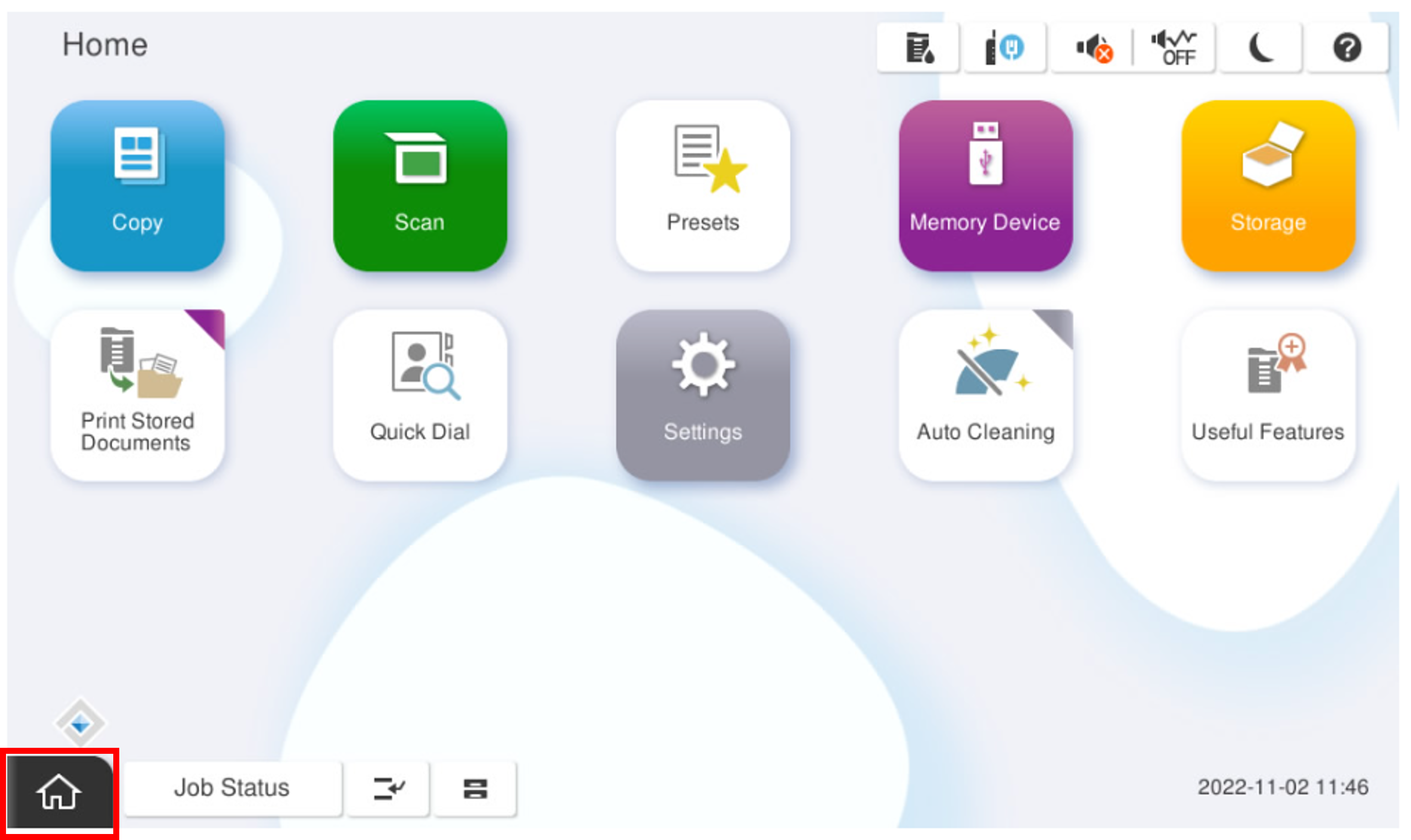
- Start the service support mode.
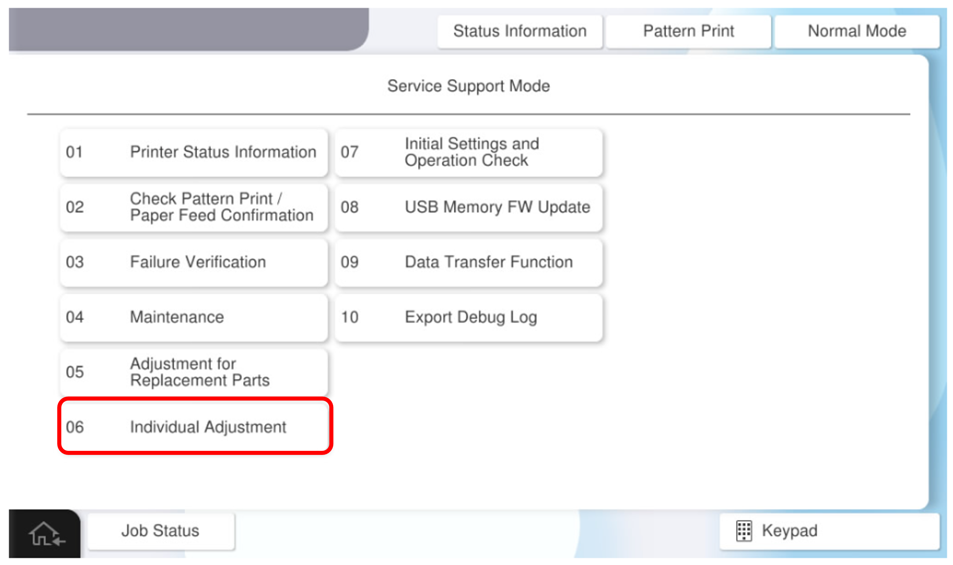
- Select [06 Individual Adjustment].
- Select [Finisher] tab.
Select [6050203 Punch Inclination Adjustment (hardware)].
- Press each setting item button to make the print settings.
The parameters that can be set are as follows.Check Point / チェックポイント- One sheet of paper is required to output the adjustment pattern.
Setting Items Selection Feed Tray C1, C2, C3, C4, Paper Tray, High Capacity Unit Available Paper Sizes A4 (Vertical), Letter (Vertical)  Caution / 注意
Make sure the paper orientation is as specified (LEF/Vertical).
If the orientation is different from the specifications (SEF/Horizontal), the paper will be ejected without being processed correctly and the operation cannot be checked.
- Press [Execute] to output the adjustment pattern.
- Fold the adjustment pattern so that the short sides of the adjustment sample overlap and the printed side is inside.
- Write the marking at the edge of overlapping hole of the adjustment pattern. If the holes are not misaligned, no adjustment is necessary.
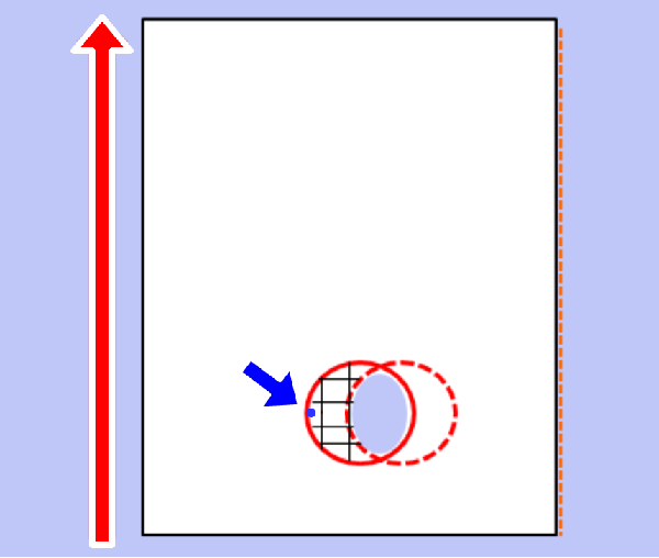
Open the alignment pattern and measure the distance (#3) between the marking and the hole outline.
Check Point / チェックポイント- If the marking is written to the right of the punch hole, attach a + sign to the measured value.
- If the marking is written to the left of the punch hole, attach a - sign to the measured value.
Convert the measurement results (#3) to adjustment values.
Check Point / チェックポイント- Adjustment value calculation method: Adjustment value = measurement result ÷ 2
Example) When the measurement result is 3 mm Adjustment value = 1.5mm
 - If the marking is written to the right of the punch hole, attach a + sign to the measured value.
- If the marking is written to the left of the punch hole, attach a - sign to the measured value.
- Adjustment value calculation method: Adjustment value = measurement result ÷ 2
Change the mounting position of the inner punch unit.
- Pull out the inner finisher.
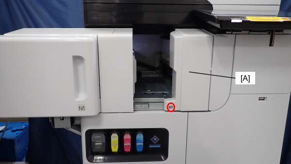
- Remove one screw and remove the front cover of the inner punch unit (A). (S7:
 )
)
- S7: C.B.STITE(P4), SCREW, 3X10, F/ZN3C
- Loosen the fixing screw (A) of the inner punch unit, and change the attachment position of the inner punch unit based on the adjustment value calculated in step 10.
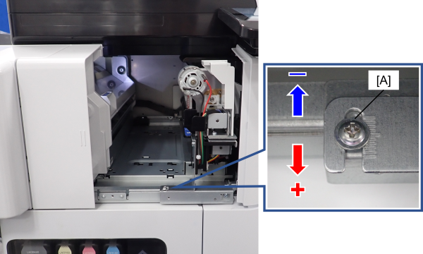 Check Point / チェックポイント
Check the parking position written on the adjustment pattern again and decide the direction to move the unit.
- When the marking is written on the right side of the punched hole (+ side)
 Move to the front side of the product.
 - When the marking is written on the right side of the punched hole (- side) Move to the back side of the product.
When moving the inner punch unit, refer to the frame memory (1 memory = 1 mm).
- When the marking is written on the right side of the punched hole (+ side)
Tighten the fixing screw (A) of the inner punch unit, and put the inner finisher back.
- Output the adjustment pattern again, and if the misalignment of the holes is improved, press [Close] to finish the adjustment and assemble the front cover of the inner punch unit.
If you need to continue adjusting, repeat the adjustment from step 8.