
Head USB Cable
- Remove the 2 screws and remove the Left Cover Upper (A).
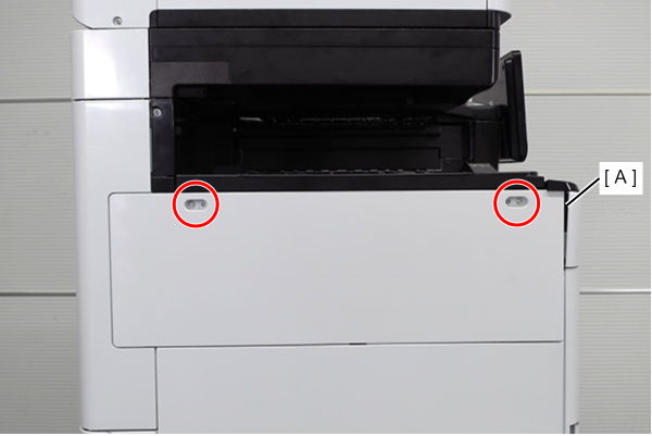
 : 3x10DW
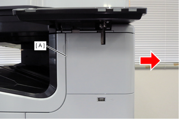
- Slide the front decorative cover upper (A) in the direction of the arrow to remove it.
- Remove one screw, and remove the front cover upper (A) in the direction of the arrow while pressing the hook.
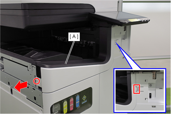
- : 3x10DW
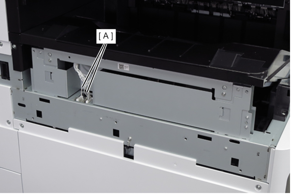
- Remove the two cables (A) from the connectors.
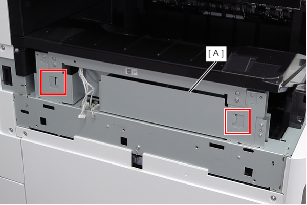
- Lift the FD frame (A), release the two hooks, and remove it to the left side of the product.
- Remove the screw that secures the ground wire (A).
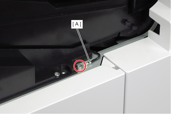
- : 3x8D
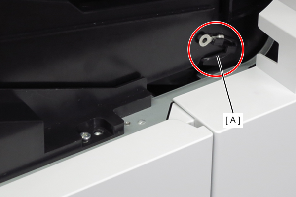
- Route the ground wire (A) around the guide.
- Remove the 4 screws that secure the FD stacker Assy (A).
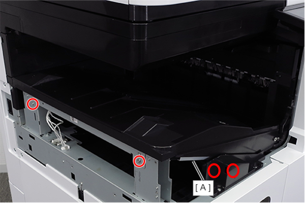
- : 3x8D
- Hold the position shown in the figure and remove the FD stacker Assy (A).
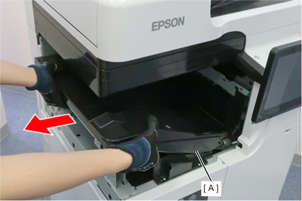
 Assembly / 組み立て
Attach the FD stacker Assy (B) along the rail of the FD stacker guide (A).
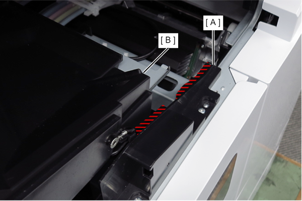
- Remove the Head USB cable (A) from the connector.
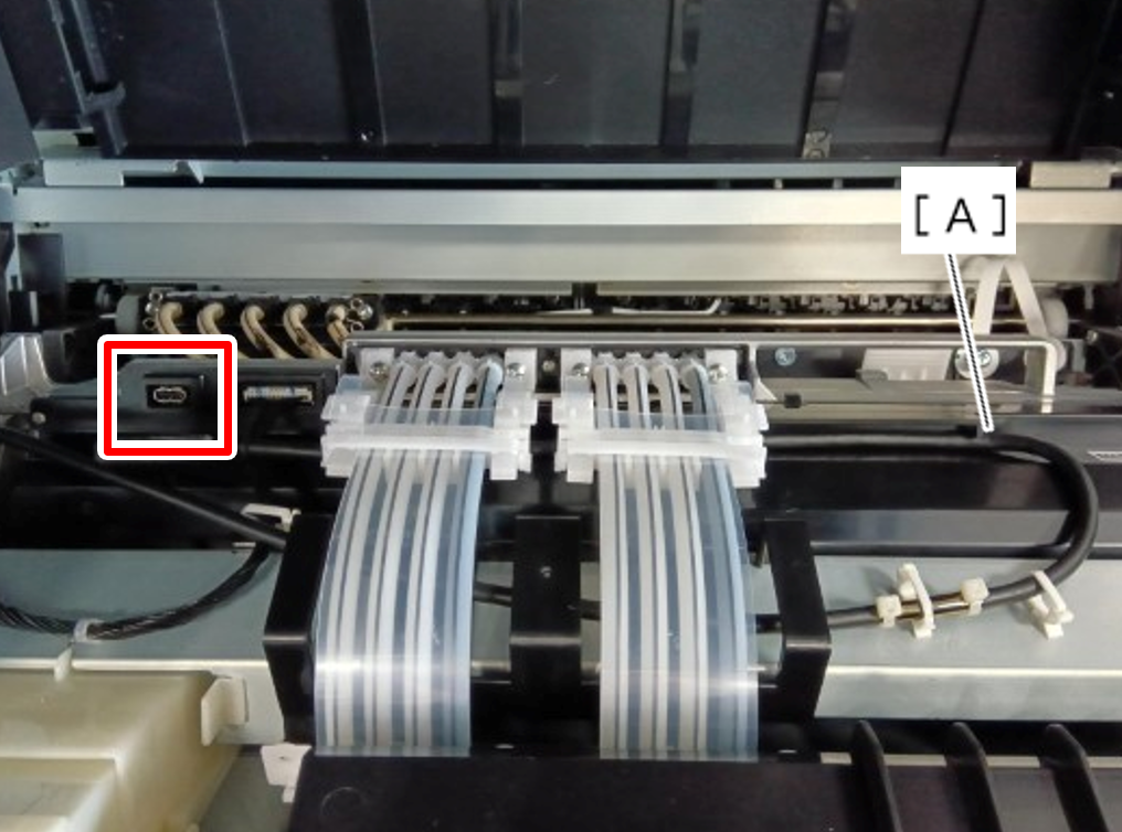
- Release the Head USB Cable (C) from the Ink Supply Tube (A) and hook (B).
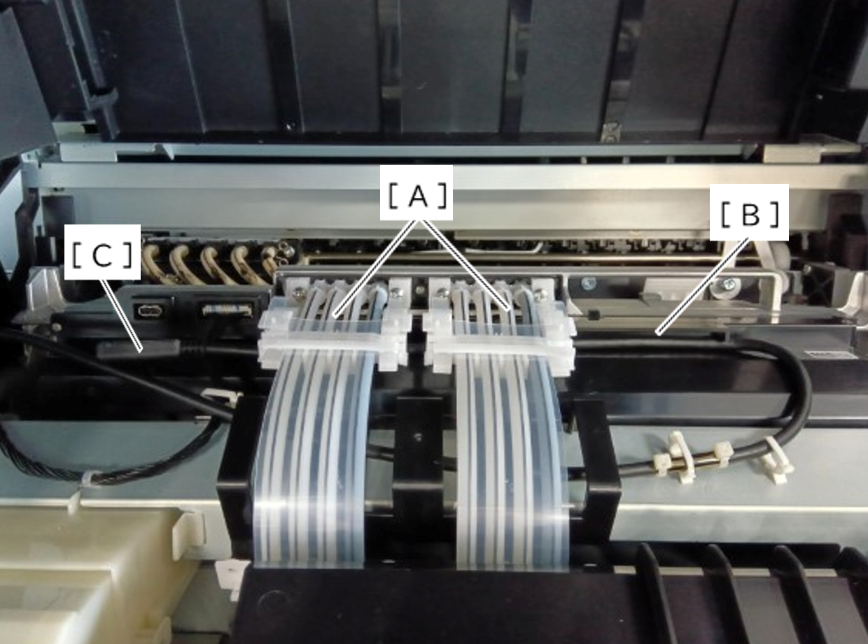
- Release the Head USB Cable (A) from the two clamps and guide.
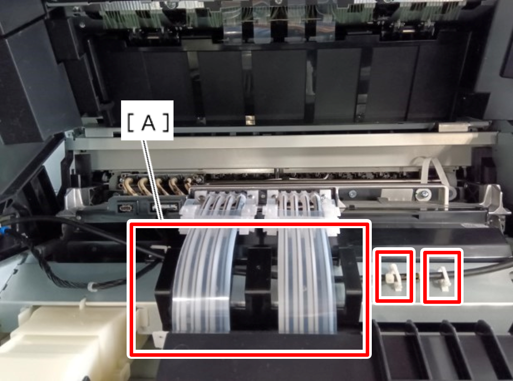 Assembly / 組み立て
- The Head USB Cable should be routed according to the following procedure.
- Straighten the head USB cable (A) and make sure it is not twisted.
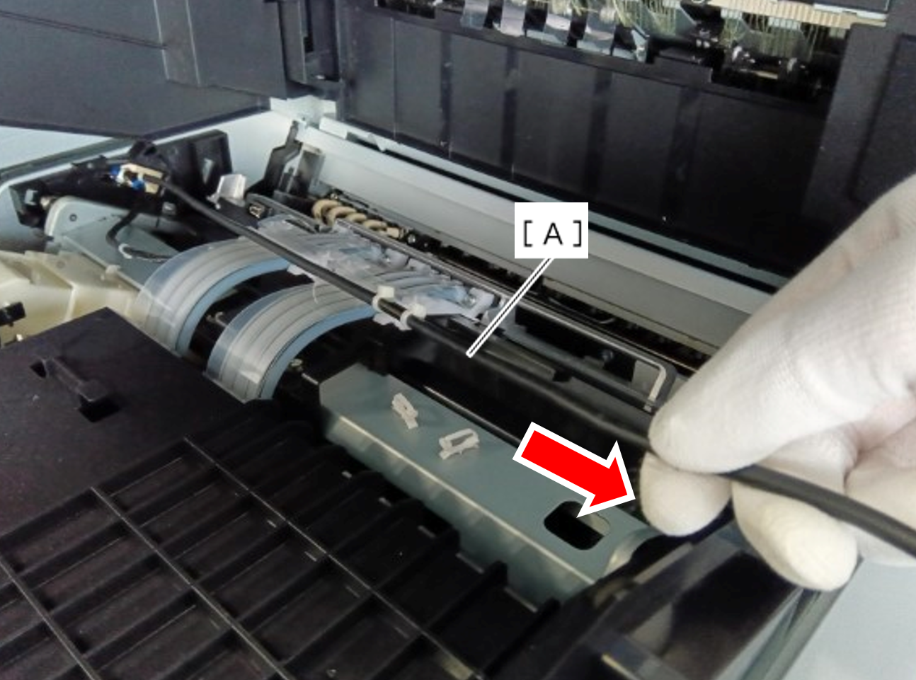
- Pass the Head USB cable through the guide and two clamps.
When doing this, align the triangle mark (A) stamped on the frame with the cable tie (C) of the cable (B).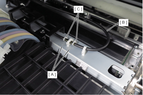
- Straighten the Head USB cable again and make sure it is not twisted.
Pass the Head USB Cable (A) under the Ink Supply Tube (B) and insert it into the hook (C).
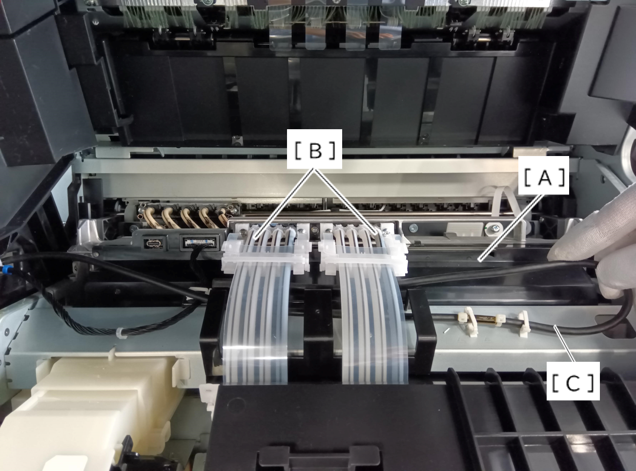
 Caution / 注意
Place the USB cable on top of the harness.
* When the harness is on the top, stress is applied to the USB cable.
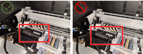
Connect the Head USB Cable to the connector.
Caution / 注意- Make sure the Head USB Cable (A) is not twisted.
- If there is any twisting, the cable may break during product operation.
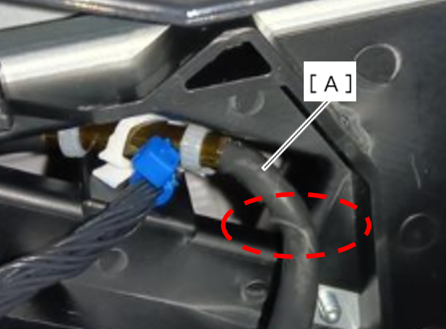
- Straighten the head USB cable (A) and make sure it is not twisted.
- The Head USB Cable should be routed according to the following procedure.
- Remove the 4 screws and remove the right cover sub (A).
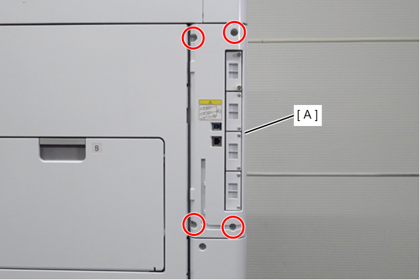
- : 3x10DW
- Remove 1 screw and slide the rear cover (A) in the direction of the arrow to remove it.
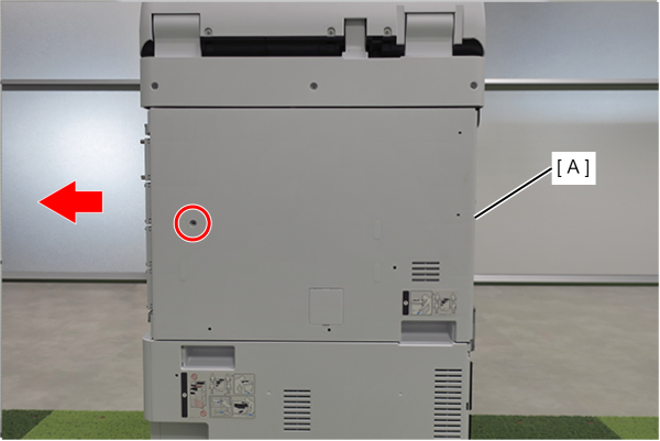
- : 3x10DW
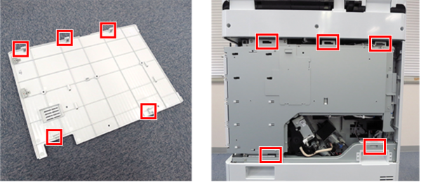
Assembly / 組み立てAlign the 5 hooks on the rear cover with the 5 holes on the main unit and attach it.
- Remove one screw and remove the shield plate (A) upwards.
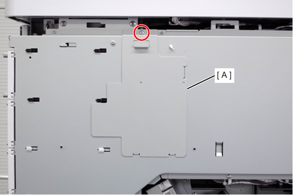
- : 3x8D
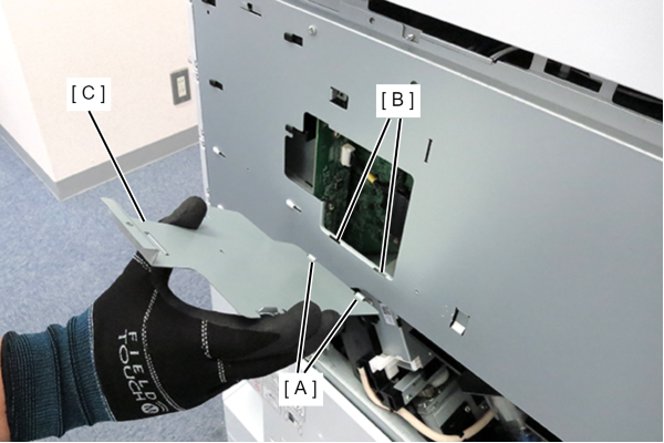
Assembly / 組み立てHook the 2 hooks (A) of the shield plate to the 2 holes (B) of the circuit board box and attach the shield plate (C).
- Disconnect the cable (A) from the connector.
- Remove 3 screws.
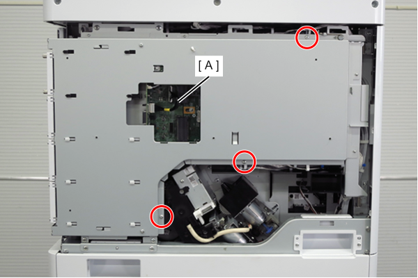
- : 3x8D
Caution / 注意When tightening screws, make sure that the screw holes are aligned before tightening.
If the screw holes do not match, the threads may be stripped.
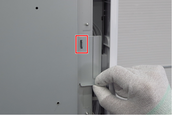
- Lift the handle to release the hook.
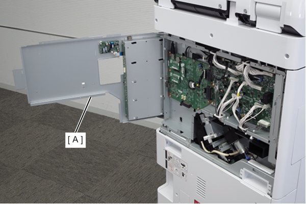
- Open the board box upper case (A).
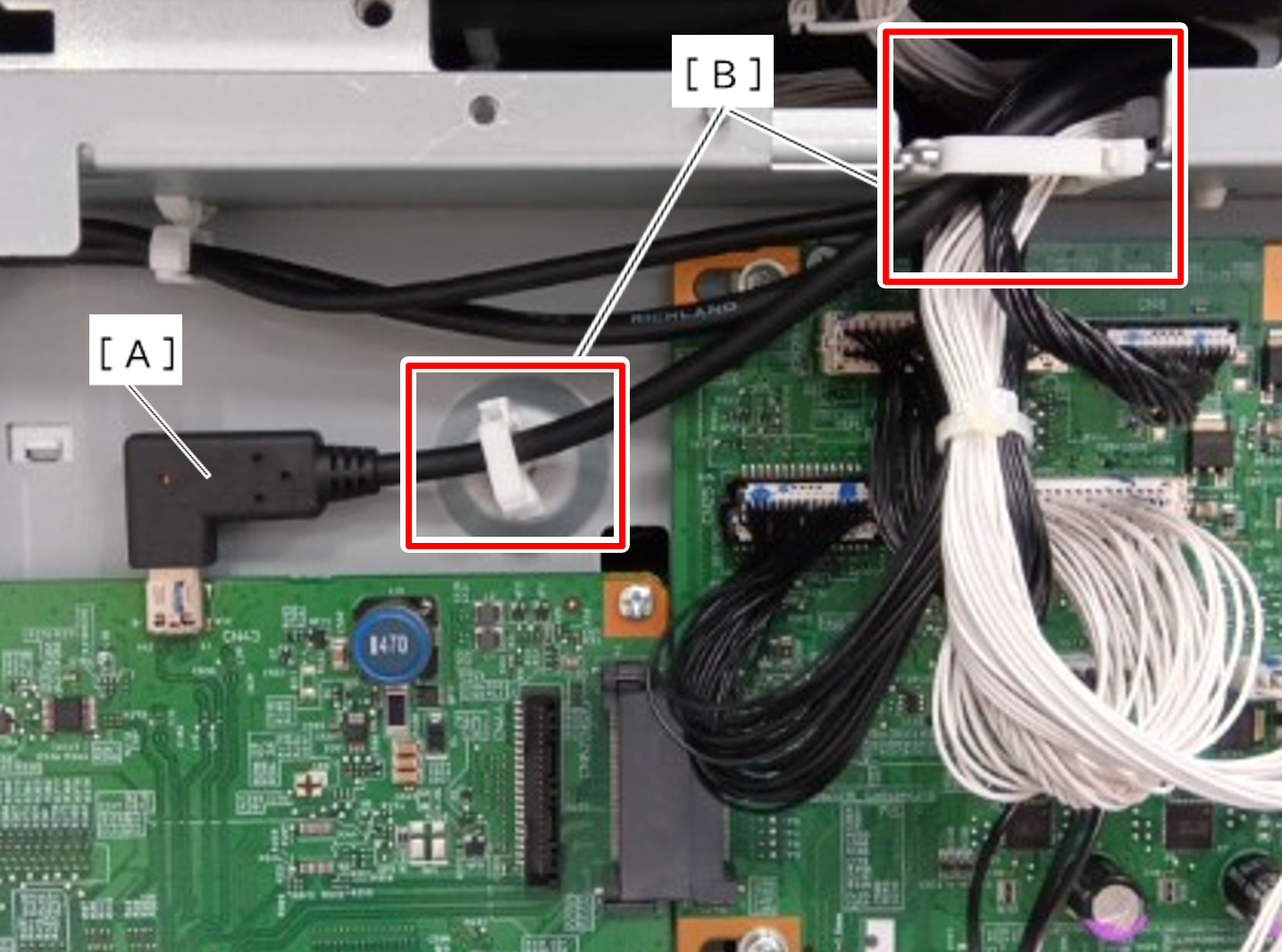
- Disconnect the Head USB Cable (A) from the connector on the Main Board and release it from the two clamps (B).
 Assembly / 組み立て
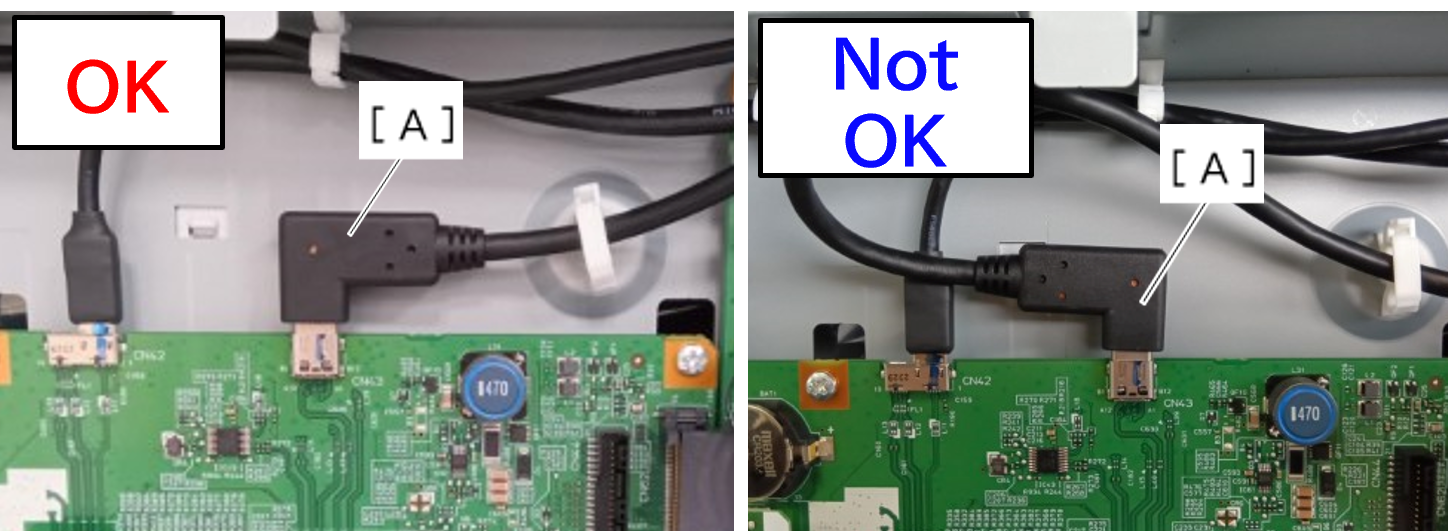
- Be careful with the direction of Head USB Cable (A).
- If the direction of Head USB Cable (A) is incorrect, a Head control Board over voltage error (060012) may occur.
- Remove 4 screws.
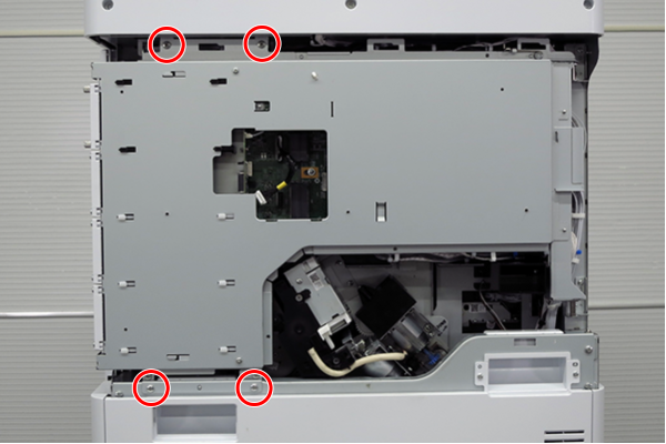
- : 4x8D
- Slightly lift the board box (A) to release the hook.
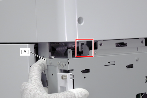
- Open the board box (A).
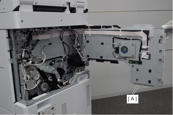
 Check Point / チェックポイント
- By hooking the hook (A) of the board box to the hole in the main body, the position of the board box is stabilized, making it easier to work.
- Do not close the circuit board box while hooking the hook (A) on the main unit. The frame may be deformed.
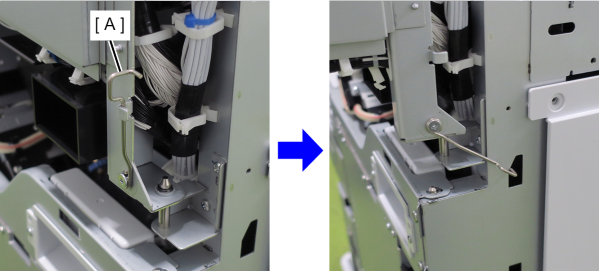
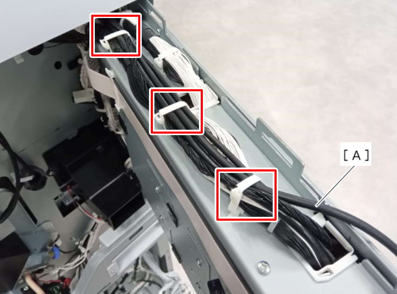
- Release the Head USB Cable (A) from the three clamps.
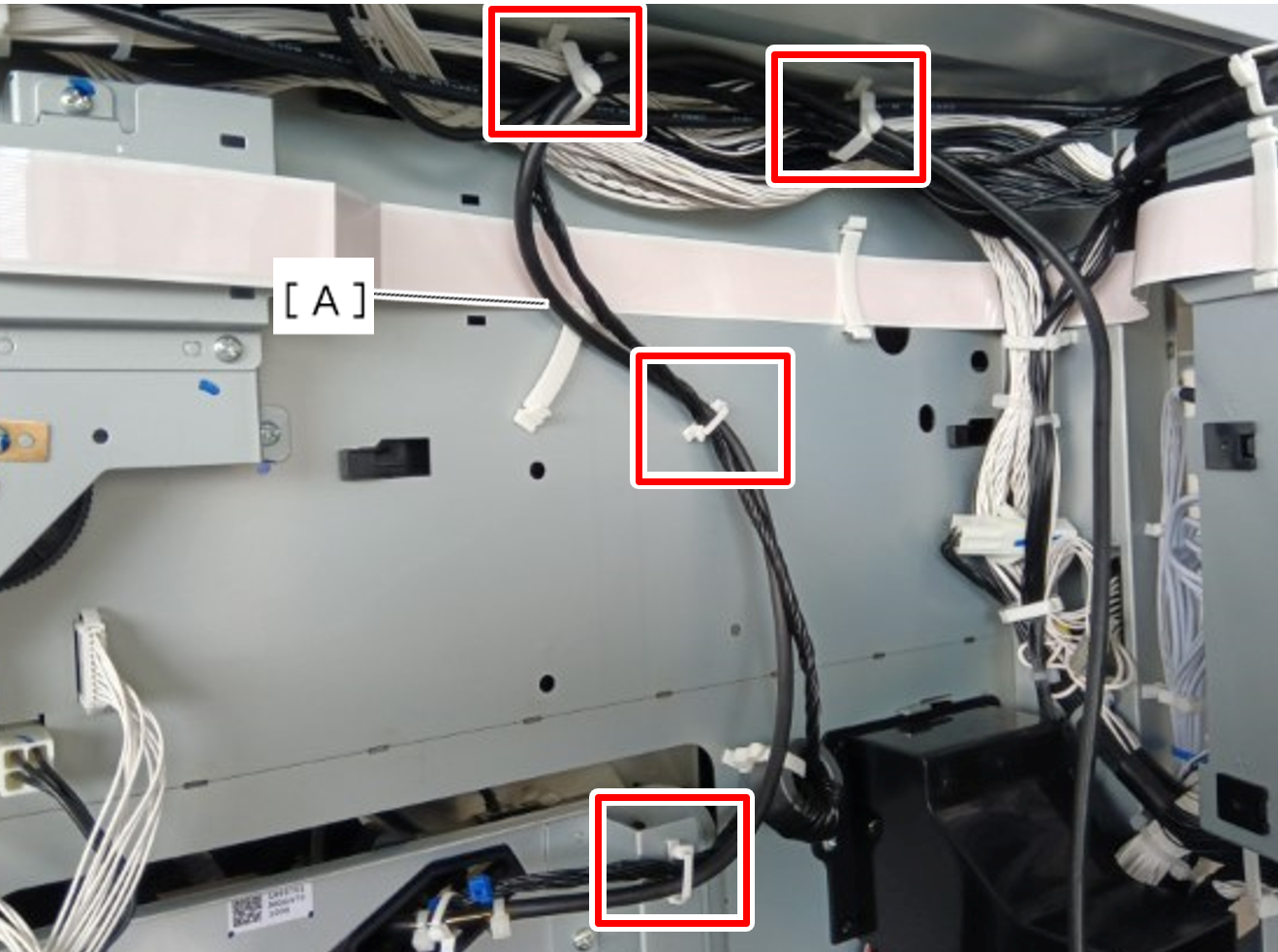
- Release the Head USB Cable (A) from the four clamps.
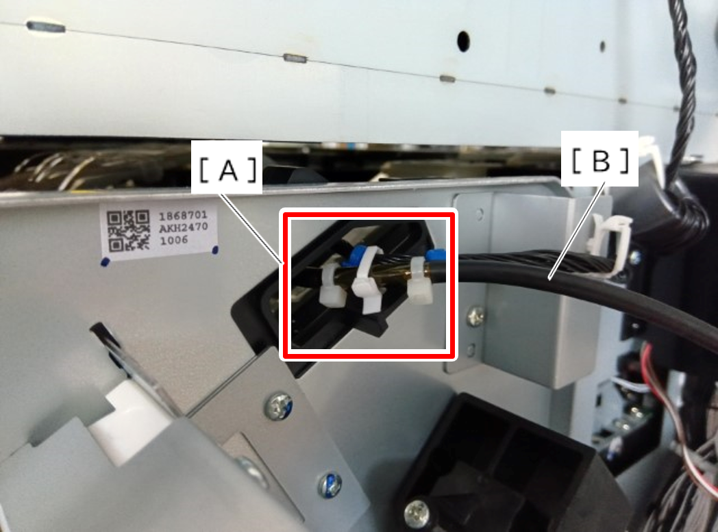
- Release the Head USB Cable (B) from the clamp (A).
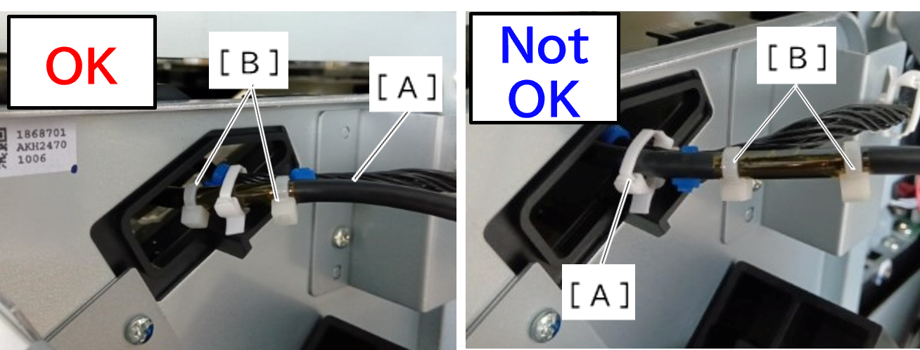
 Assembly / 組み立て
- Clamp Head USB Cable (A) between the two cable ties (B).
- This procedure is used to manage the excess length of the Head USB Cable.
- Pull out the Head USB Cable (B) from the hole (A) in the frame and remove it.
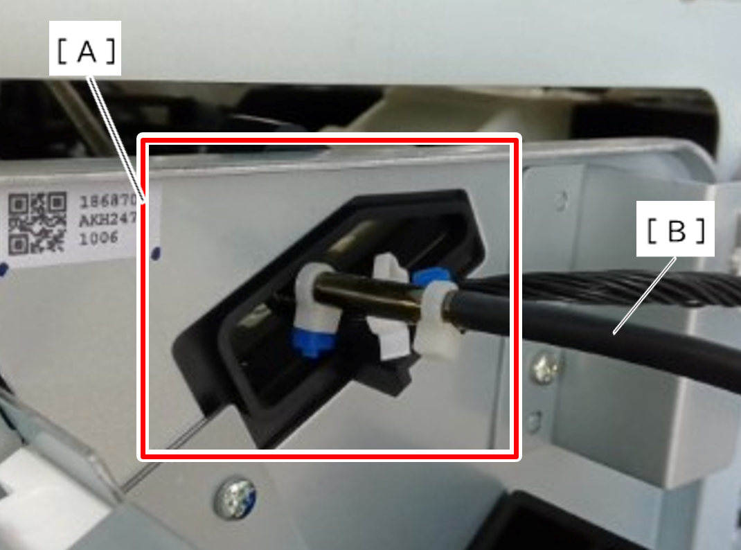 Caution / 注意
At this time, be careful not to damage other harness.
Assembly / 組み立て- Insert the Head USB Cable through the frame hole with the side that has cable tie (C) facing the head.
- A: Head side
- B: Main Board side
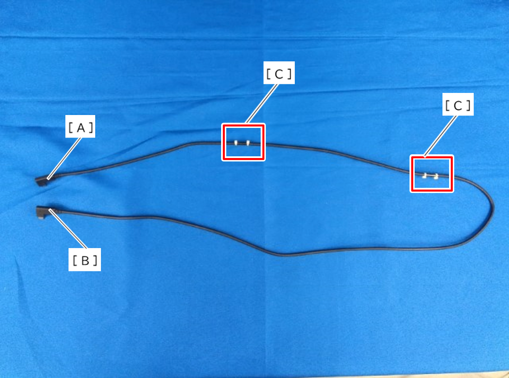
- Insert the Head USB Cable through the frame hole with the side that has cable tie (C) facing the head.