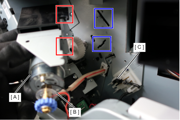
Head Lifting Motor Assy
- Remove the 2 screws and remove the Left Cover Upper (A).
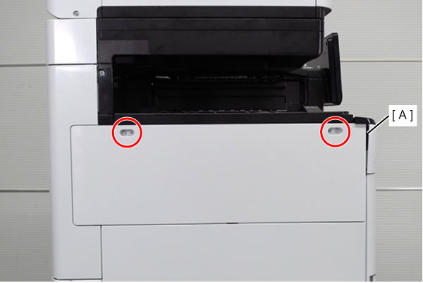
 : 3x10DW
- Remove the two screws and slide the Left Cover Sub Upper (A) in the direction of the arrow to remove it.
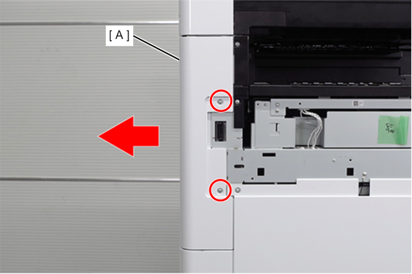
- : 3x10DW
- Remove the 4 screws and remove the right cover sub (A).
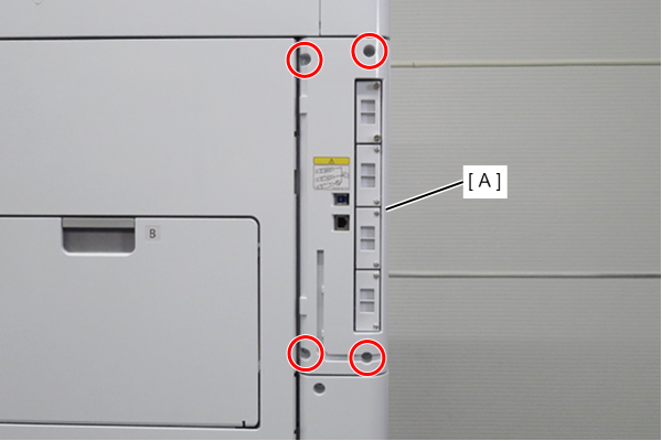
- : 3x10DW
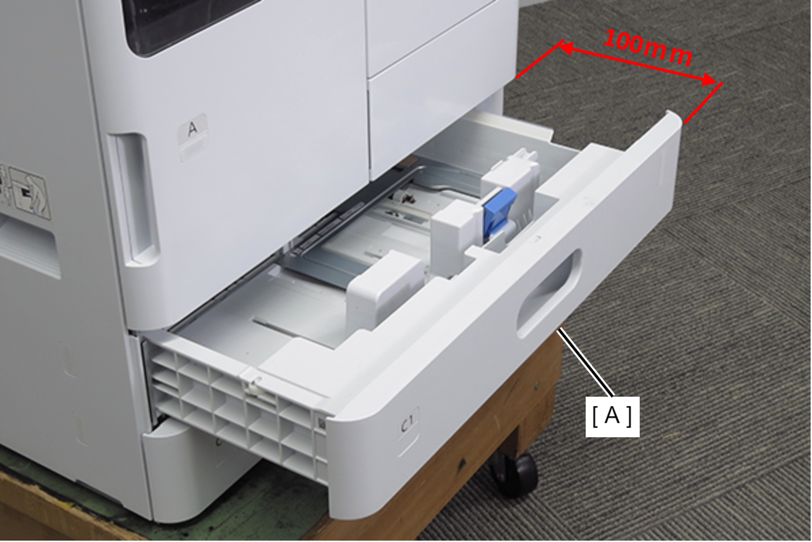
- Pull out the C1 cassette (A). (about 100mm)
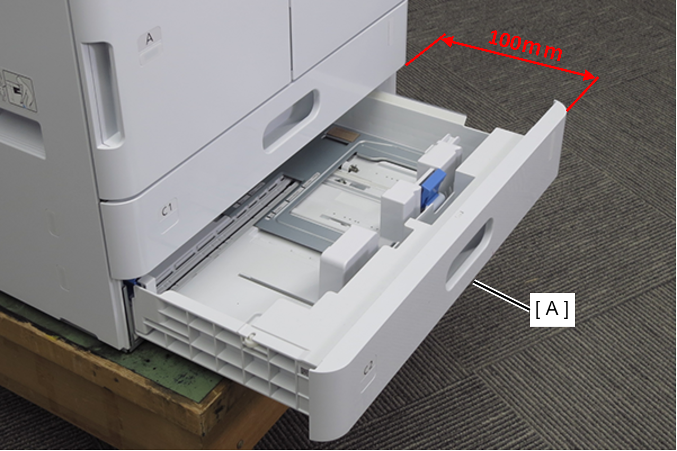
- Pull out the C2 cassette (A). (about 100mm)
- Remove 2 screws and remove the Left Cover Lower (A) in the direction of the arrow.
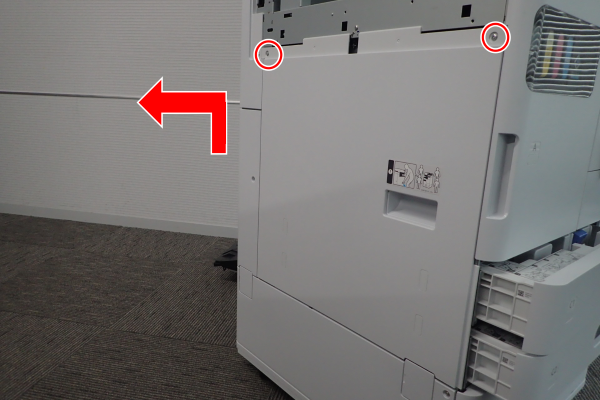
- : 3x10DW
- Remove 1 screw and slide the rear cover (A) in the direction of the arrow to remove it.
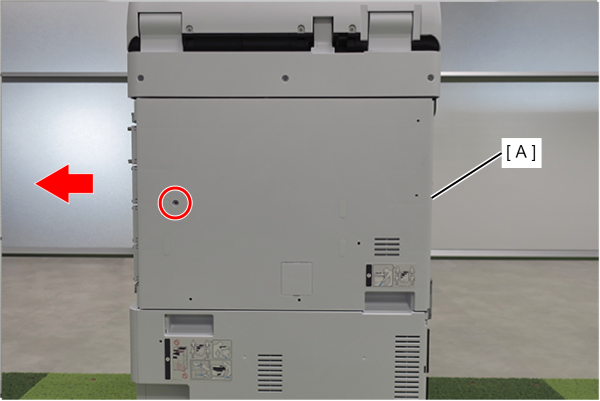
- : 3x10DW
 Assembly / 組み立て
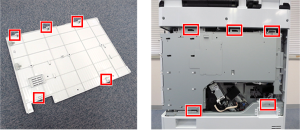
Align the 5 hooks on the rear cover with the 5 holes on the main unit and attach it.
- Remove 1 screw and remove the Left Cover Sub Lower (A) in the direction of the arrow.
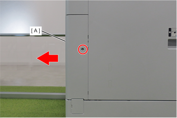
- : 3x10DW
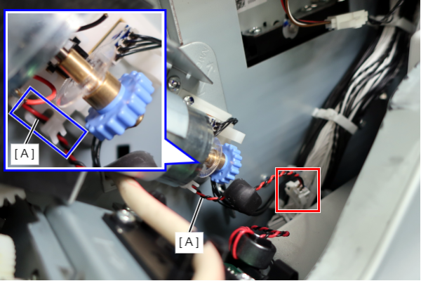
- Disconnect the cable (A) from the connector.
- Release the cable (A) from the guide.
 Caution / 注意
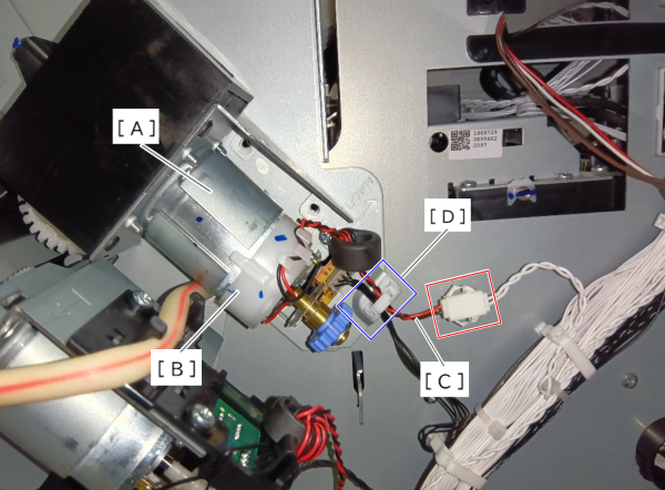
Depending on the production period, a cover part (B) may be attached to the Head Lifting Motor Assy (A).
If the cover part (B) is attached, the routing will be different, so release the cable (C) from the clamp (D).
 Assembly / 組み立て
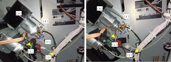
The routing of the cable is depending on the shape of the Head Lifting Motor Assy (A) and the Head Encoder Holder (E).
Route the cable according to the instructions below.If the cover part (B) is not attached to the Head Lifting Motor Assy (A)
1. Route both the cable (C) of the Head Lifting Motor Assy and the white cable (D) downward.
2. Depending on the shape of the Head Encoder Holder (E), route the cable through the guide part (F).
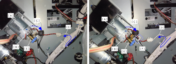
If the cover part (B) is attached to the Head Lifting Motor Assy (A)
1. Route both the cable (C) of the Head Lifting Motor Assy and the white cable (D) upward.
2. Depending on the shape of the Head Encoder Holder (E), route the cable through the clamp (F).
- Remove 3 screws.
Pull the Head Lifting Motor Assy (A) forward, and remove the Head Lifting Motor Assy (A) in the direction of the arrow while avoiding the sensor so that the scale (B) will not be damaged.
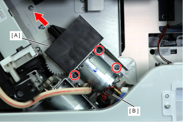
- SX: 3x8D/P
Assembly / 組み立てWhen installing the Head Lifting Motor Assy (A), align the 2 protrusions with the notches on the main unit so that the scale (B) does not hit the sensor (C).