
C2 Paper Size Detection Sensor Assy
- Remove the 2 screws and remove the Left Cover Upper (A).
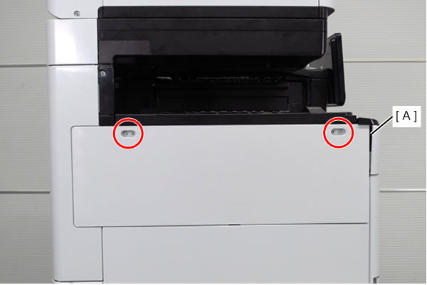
 : 3x10DW
- Remove the two screws and slide the Left Cover Sub Upper (A) in the direction of the arrow to remove it.
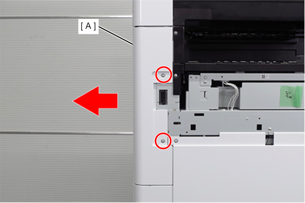
- : 3x10DW
- Remove the 4 screws and remove the right cover sub (A).
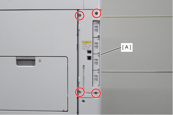
- : 3x10DW
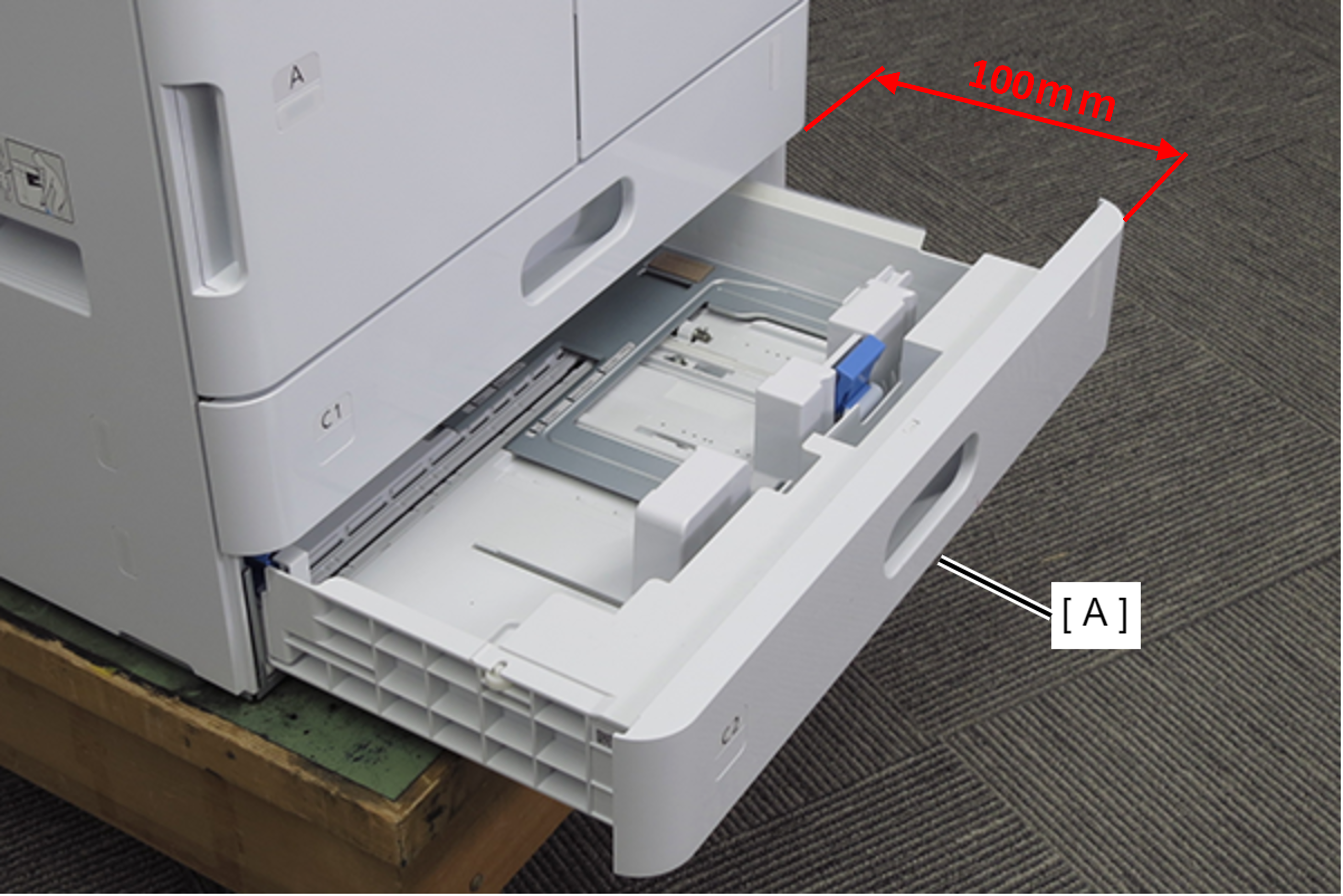
- Pull out the C1 cassette (A). (about 100mm)
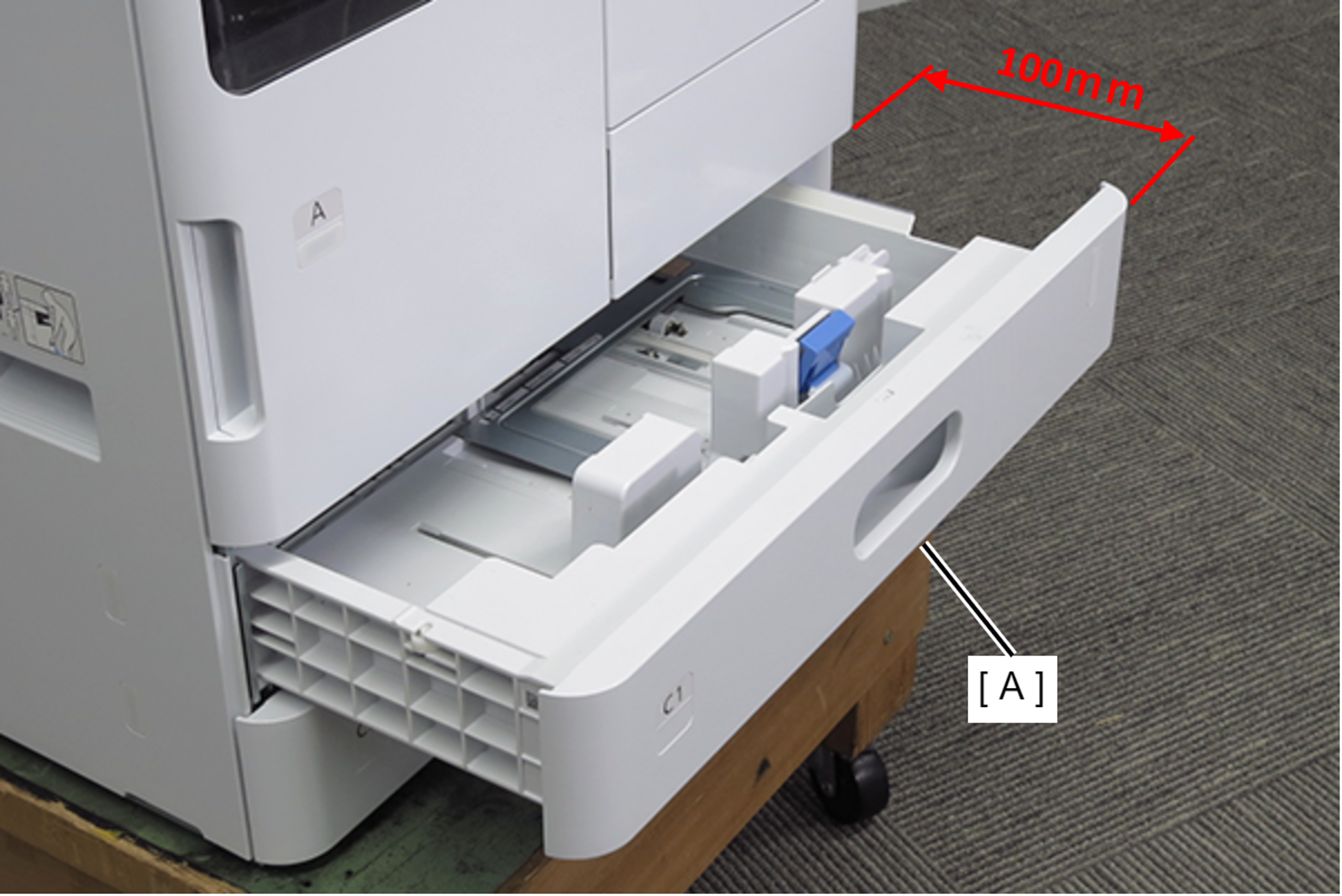
- Pull out the C2 cassette (A). (about 100mm)
- Remove 2 screws and remove the Left Cover Lower (A) in the direction of the arrow.
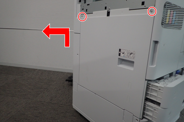
- : 3x10DW
- Remove 1 screw and slide the rear cover (A) in the direction of the arrow to remove it.
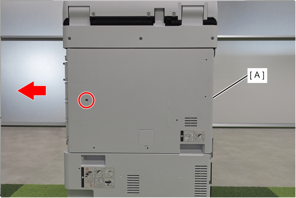
- : 3x10DW
 Assembly / 組み立て
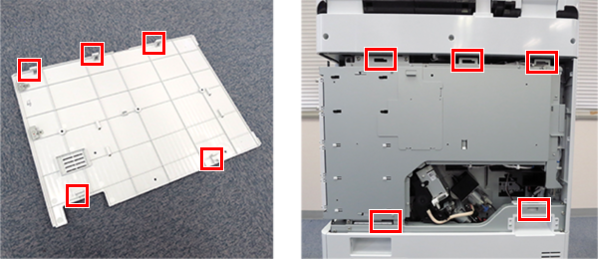
Align the 5 hooks on the rear cover with the 5 holes on the main unit and attach it.
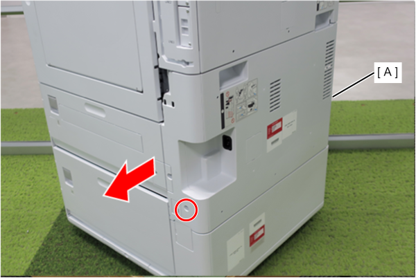
- Remove 1 screw and remove the Left Cover Sub Lower (A) in the direction of the arrow.
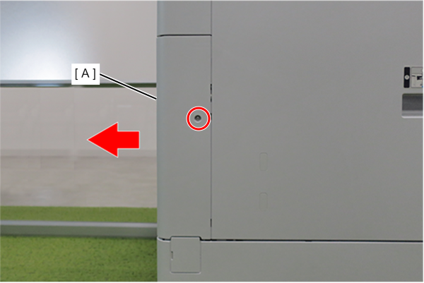
- : 3x10DW
- Remove 4 screws.
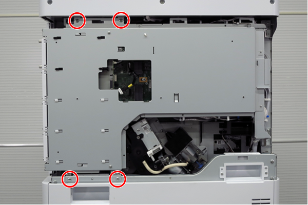
- : 4x8D
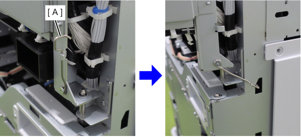
- Slightly lift the board box (A) to release the hook.
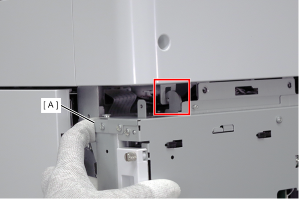
- Open the board box (A).
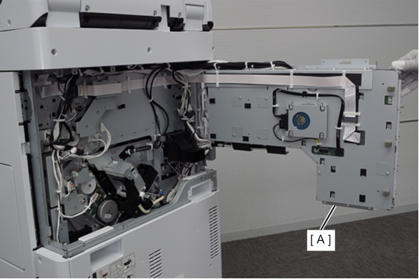
 Check Point / チェックポイント
- By hooking the hook (A) of the board box to the hole in the main body, the position of the board box is stabilized, making it easier to work.
- Do not close the circuit board box while hooking the hook (A) on the main unit. The frame may be deformed.
- Remove one screw and remove the Rear cover lower (A) in the direction of the arrow.
- : 3x10DW
- Remove 8 screws and open the power supply box (A).
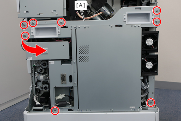
- : 4x8D/P
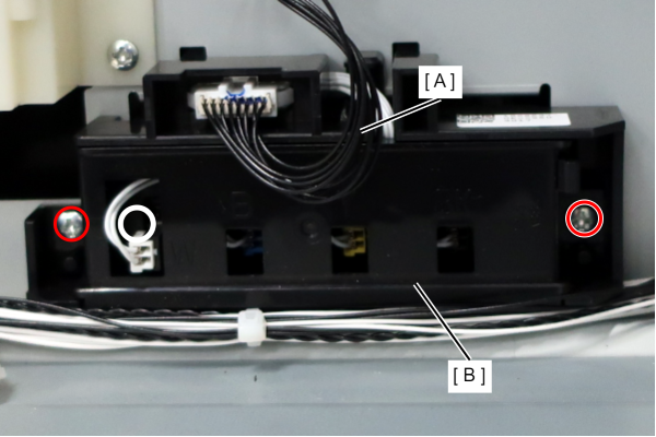
- Disconnect the cable (A) from the connector.
- Remove 2 screws and remove the C2 Paper Size Detection Sensor Assy (B).
-
- : 3x8D/P