Paper Guide Feed1 Assy
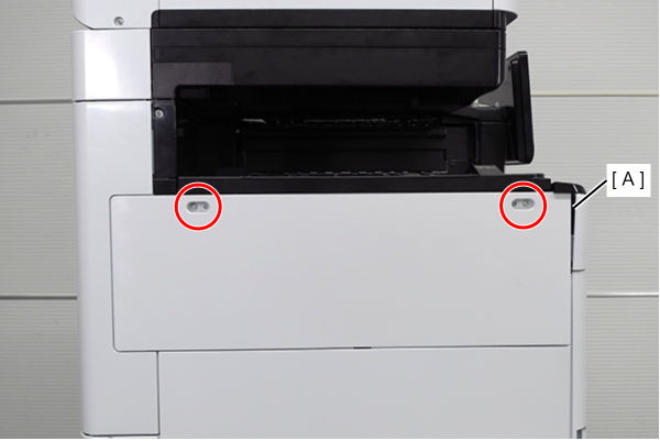
- Release the 2 dowels with a flathead screwdriver and remove the Front Cover (A).
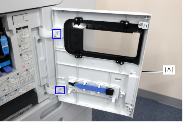
- Remove the 2 screws and remove the Left Cover Upper (A).
 : 3x10DW
- Remove one screw, and remove the front cover upper (A) in the direction of the arrow while pressing the hook.
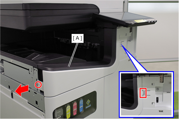
- : 3x10DW
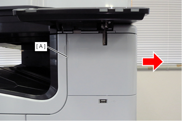
- Slide the front decorative cover upper (A) in the direction of the arrow to remove it.
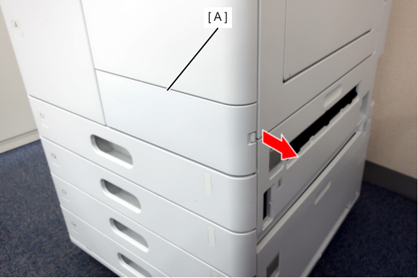
- Release the hook and remove the Front Decorative Cover Lower (A) in the direction of the arrow.
- Remove 6 screws and remove the Front Right Cover (A).
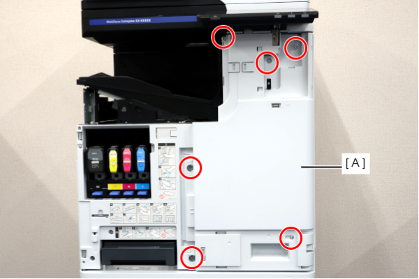
- : 3x10DW/P
- Remove 1 screw and remove the Stay Plate (A).
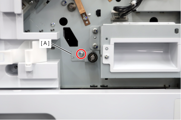
- : 3x8D/P
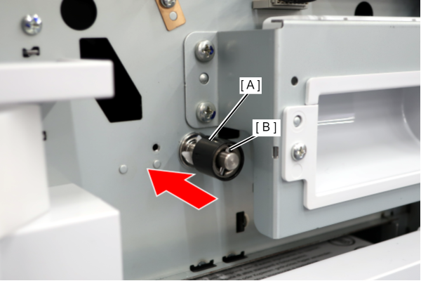
- Push in the torque limiter (A) and remove the pin (B).
 Caution / 注意
Be careful not to lose the pin (B) because it is easy to drop.
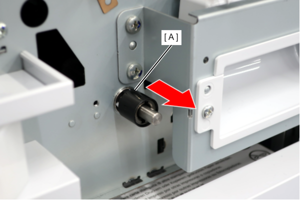
- Remove the Torque Limiter (A).
- Remove the 4 screws and remove the right cover sub (A).
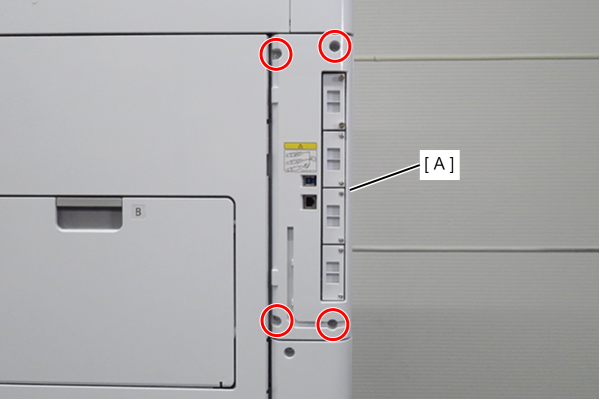
- : 3x10DW
- Remove the two screws and slide the Left Cover Sub Upper (A) in the direction of the arrow to remove it.
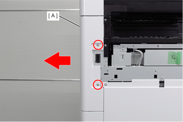
- : 3x10DW
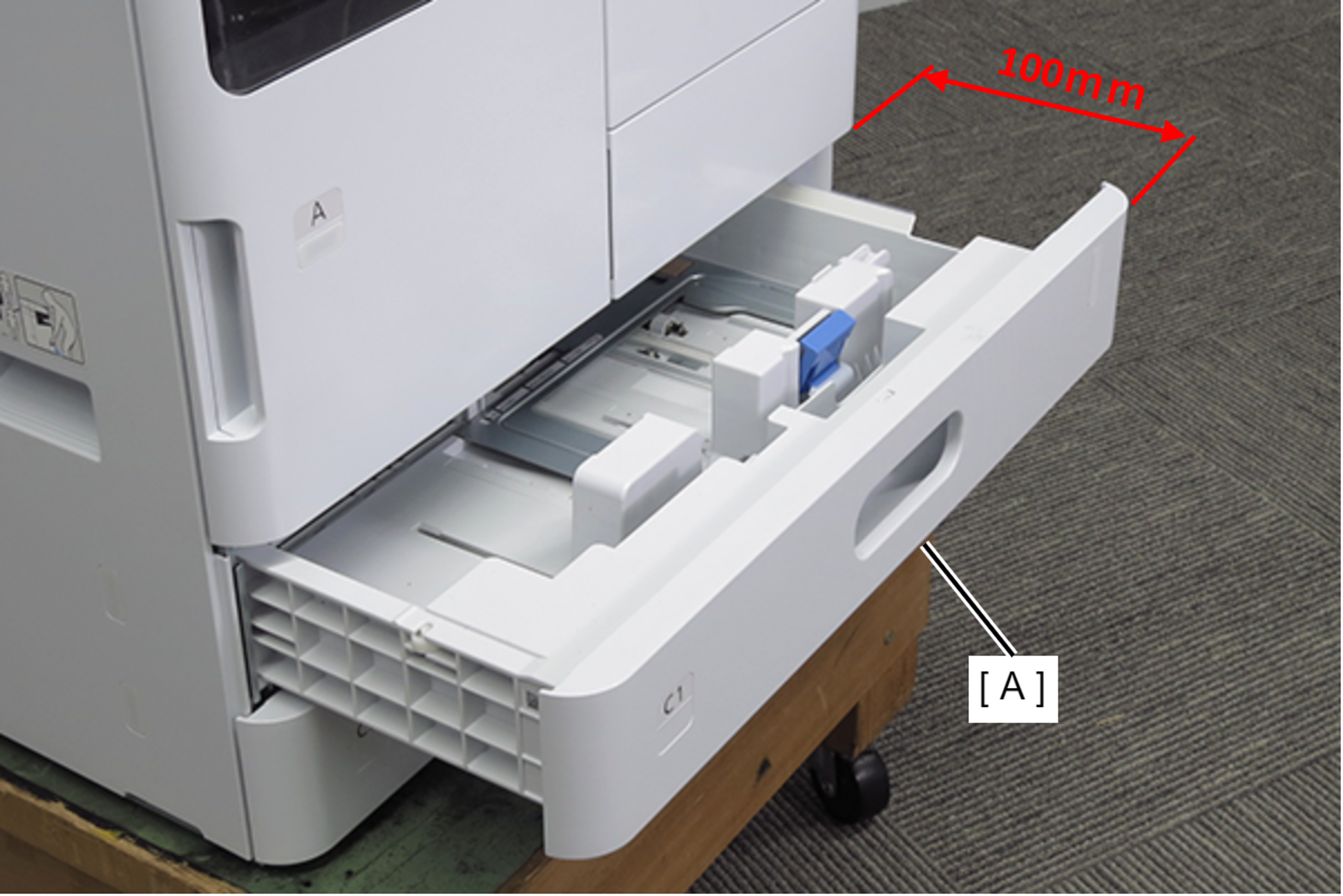
- Pull out the C1 cassette (A). (about 100mm)
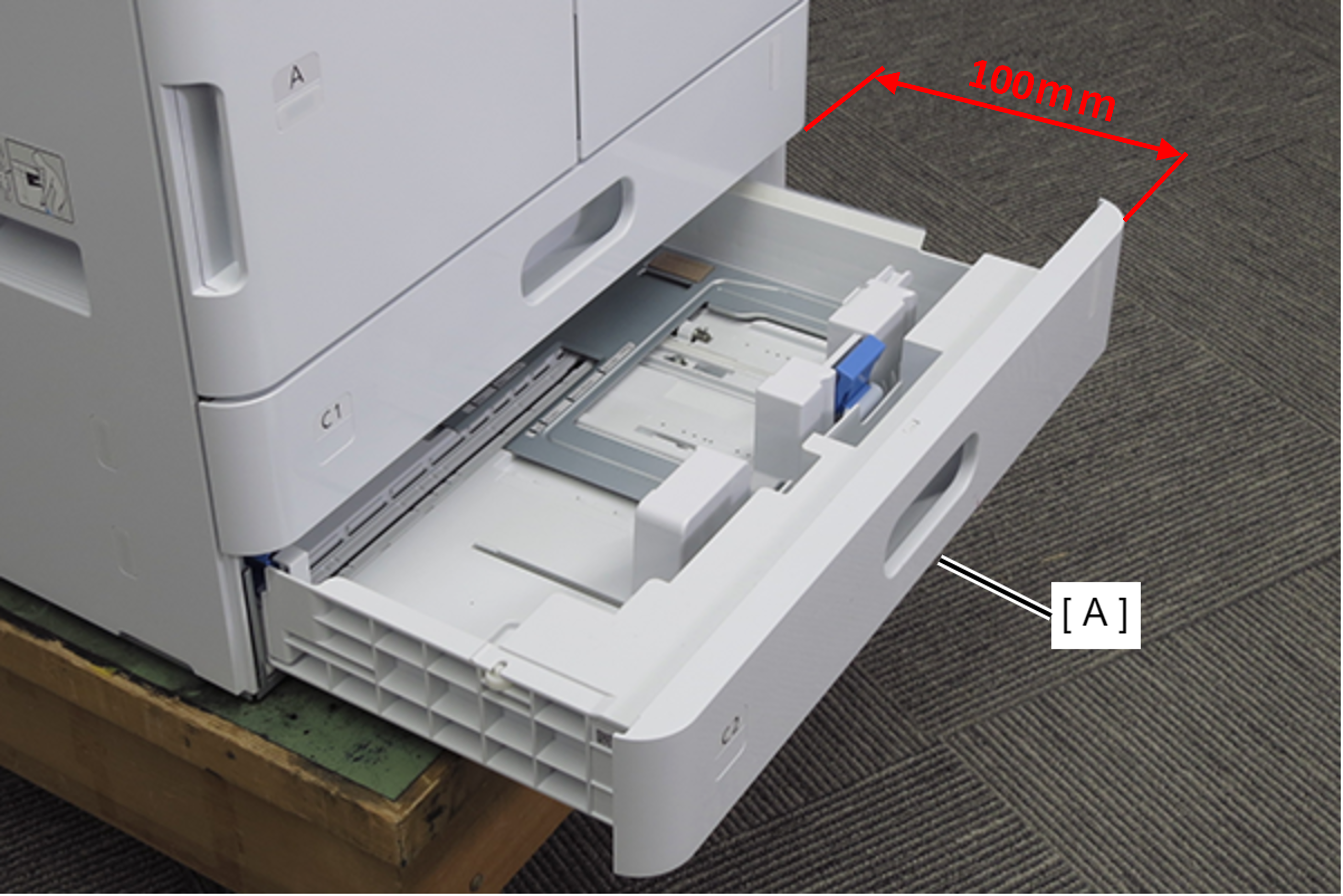
- Pull out the C2 cassette (A). (about 100mm)
- Remove 2 screws and remove the Left Cover Lower (A) in the direction of the arrow.
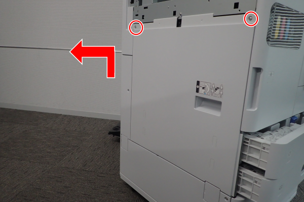
- : 3x10DW
- Remove 1 screw and remove the Left Cover Sub Lower (A) in the direction of the arrow.
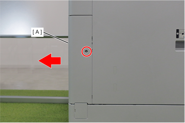
- : 3x10DW
- Remove one screw and remove the Rear cover lower (A) in the direction of the arrow.
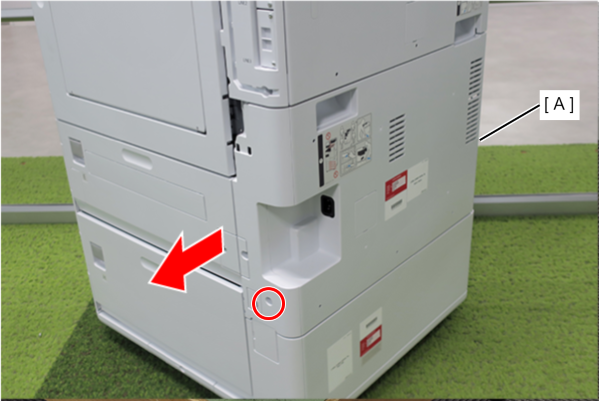
- : 3x10DW
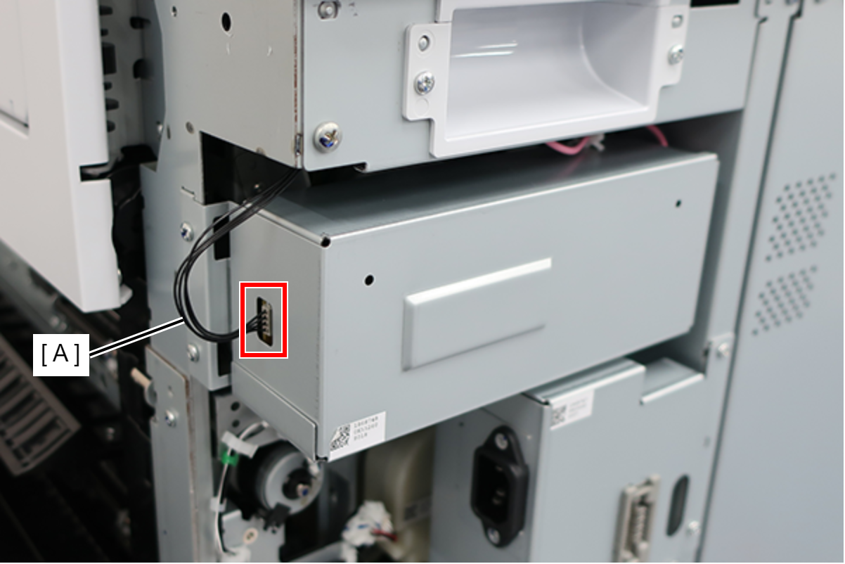
- Disconnect the cable (A) from the connector.
- Remove 2 screws and remove the High Voltage Board Cover (A).
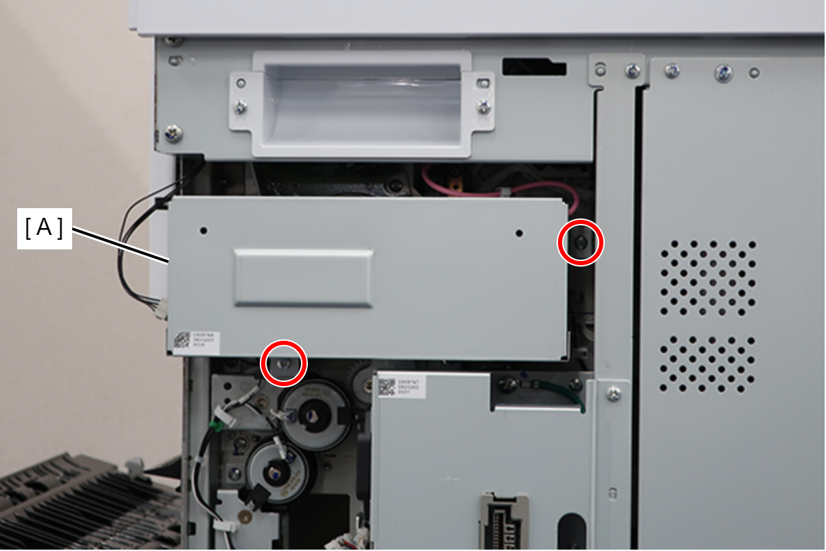
 : 3x8D/P
- Remove 3 screws.
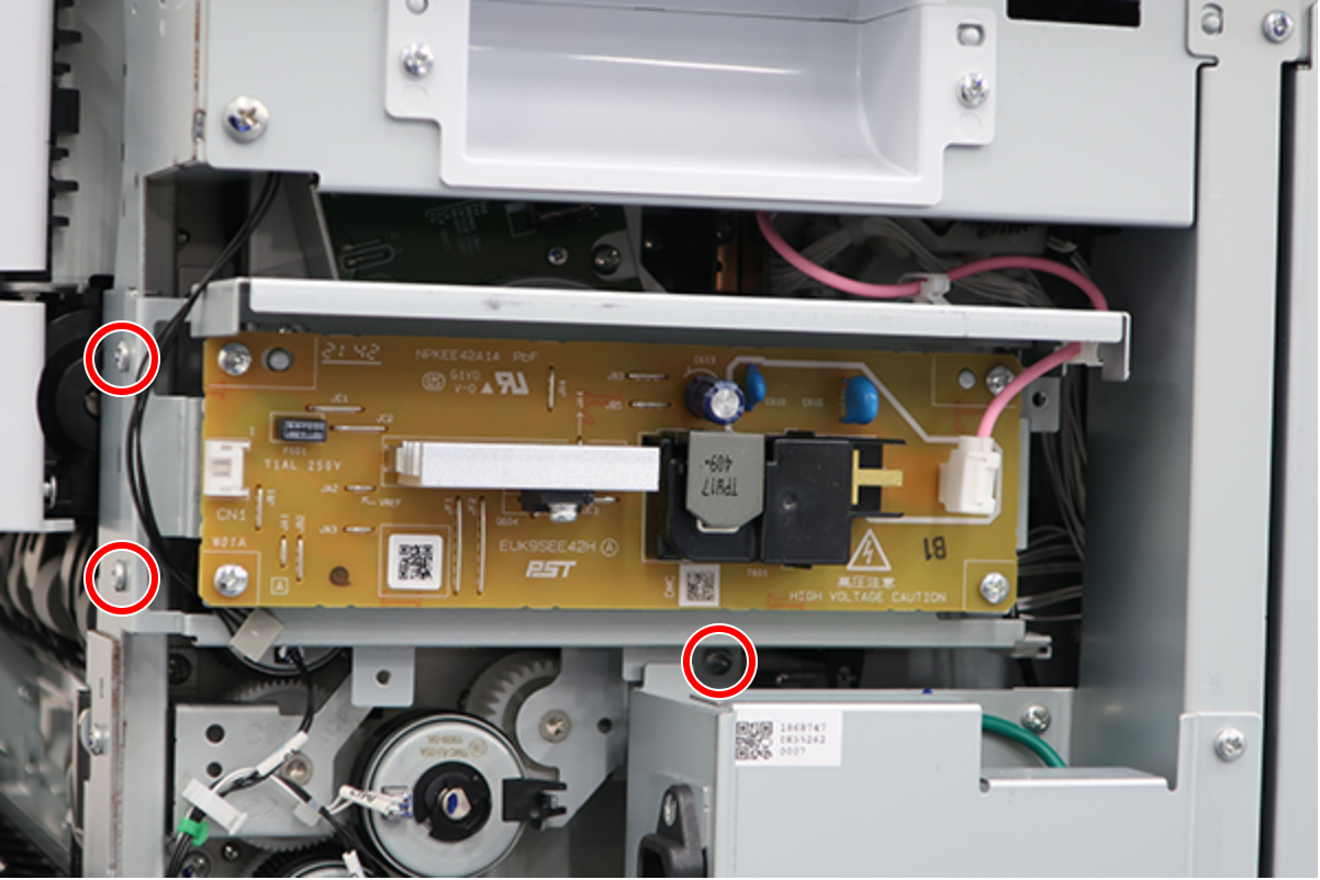
- : 3x8D/P
- Release the 2 clamps.
- Disconnect the cable (A) from the connector and remove the High Voltage Power Supply Assy (B).
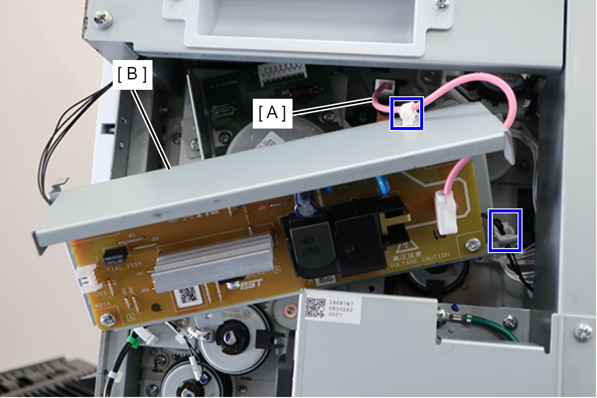
- Disconnect the cable (A) from the connector.
- Remove the C ring (B) and remove the Clutch, Paper Guide feed1 (C).
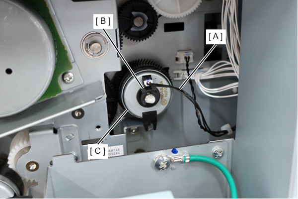
 Assembly / 組み立て
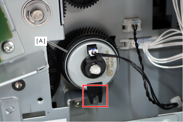
Align the concave portion of the Clutch, Paper Guide feed1 (C) with the protrusion on the main unit.
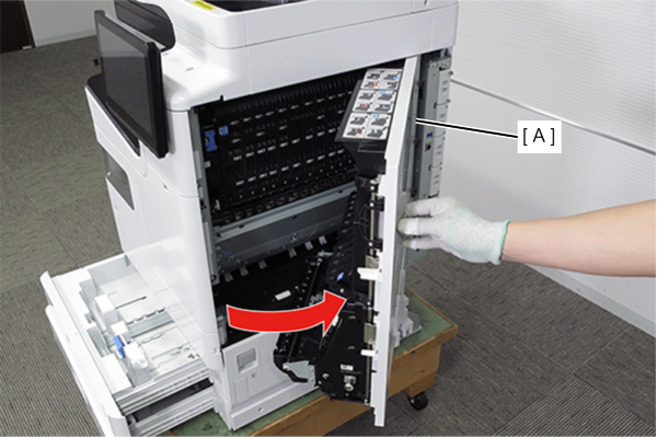
- Pull the lever to open the Right Door Unit (A).
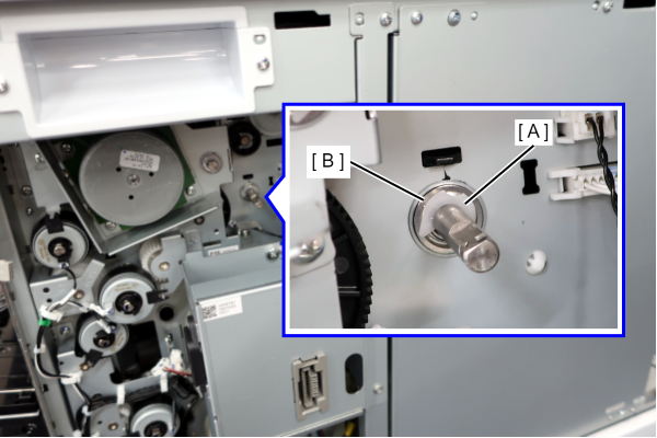
- Remove the E-ring (A) on the rear side and remove the bearing (B).
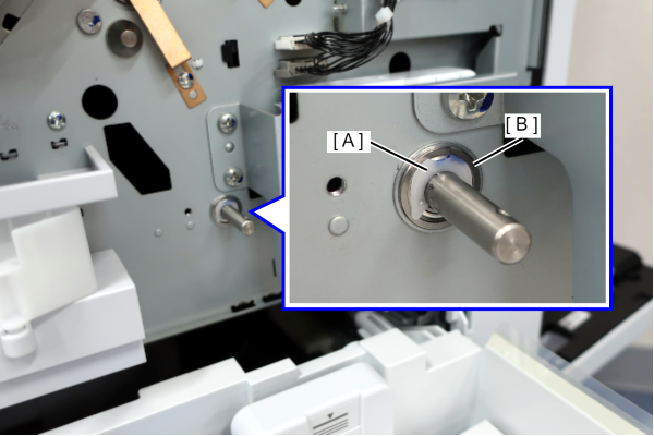
- Remove the E-ring (A) on the front side and remove the bearing (B).
- Remove the 3 screws from the Pre-PW Paper Guide (A).
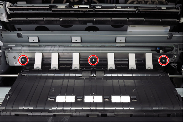
- : 3x5D
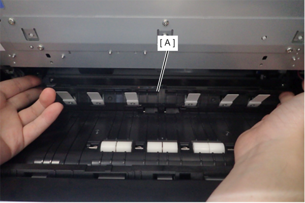
- Tilt the Pre-PW Paper Guide (A) toward you and lift up to remove it.
- Open the Paper Guide feed1 Assy (A), remove the 2 screws, and remove the bearing Assy (B).
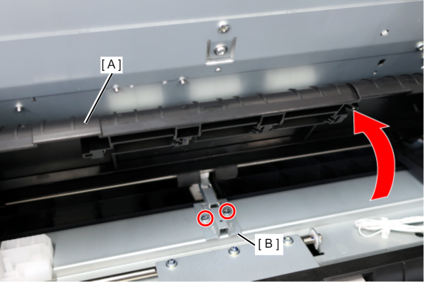
- : 3x8D/P
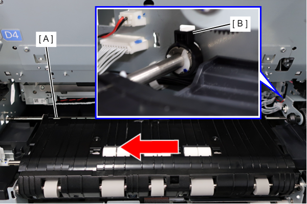
Move the Paper Guide feed1 Assy (A) in the direction of the arrow to remove the bearing (B) and remove the Paper Guide feed1 Assy.