
Ink System Mechanism
Overview
The ink system mechanism mainly has the following roles.
- Stable supply of ink to the head unit.
- Stable ejection of ink from the head unit
- Collect and discharge ink that is not used for printing (waste ink) discharged from the head unit
The main components of this product are as follows.
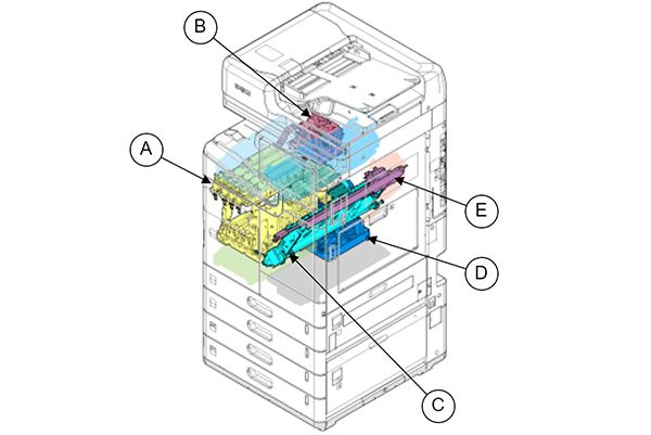
| A | Ink Supply Unit | It has a tank that stores the ink supplied from the I/C, and the remaining amount of ink is managed by a sensor inside the tank. It also has an ink flow path and an air flow path up to the head unit. |
|---|---|---|
| B | Selector Unit | The air pump is driven to pressurize/depressurize the inside of the ink/air flow path required for ink filling/head cleaning. |
| C | Cap Unit | Adheres to the head unit while waiting for printing to keep the print surface moist. To collect ink not used for printing ejected from a head unit. |
| D | Maintenance Unit | The waste ink is transferred to the maintenance box by decompressing the waste ink channel by driving the air pump. In addition, it has a tank that stores moisturizing liquid, and the remaining amount of moisturizing liquid is managed by a sensor inside the tank. |
| E | Wiper Unit | The wiper blade is brought into contact with the print surface of the head unit and moved left and right to clean foreign matter. |
| --- | Ink cartridge (I/C) | A container that holds ink used for printing. The ink cartridge of this product contains ink directly in a plastic container. Ink is supplied to the ink supply unit by attaching it to a predetermined position inside the product. |
| --- | Maintenance box | A container for storing collected waste ink. In addition, a moisturizing liquid to be used when the remaining amount of moisturizing liquid is low is enclosed inside the container. |
Ink supply control
This product uses the potential energy generated from the positional relationship between the ink level in the ink supply unit's sub-tank/reservoir tank and the head unit to supply ink (after ink is filled).
Therefore, it is necessary to set the product tilt within ±3°.
Head Cleaning
Ink filling/head cleaning (CL0/CL1/CL2) is performed by combining the following three types of control.
Pressurization Cleaning
- The air pump of the selector unit pressurizes the ink tank inside the ink supply unit.
- Ink is supplied to the head unit by the pressure accumulated inside the ink tank, and the ink is discharged.
Circulation Cleaning
- The air pump of the selector unit pressurizes the ink tank inside the ink supply unit.
- Ink is supplied to the head unit by the pressure accumulated inside the ink tank, and the ink is discharged.
- A part of the ink supplied to the head is returned to the ink tank of the ink supply unit through the ink circulation channel by valve control of the ink channel.
*By circulating ink between the ink supply unit and the head unit, efficient head cleaning is performed, reducing the amount of maintenance ink and execution time.
Pressure wiping
- The air pump of the selector unit decompresses the CL0 unit inside the ink supply unit.
- A certain amount of ink is supplied by expanding the internal volume of the CL0 unit due to the reduced pressure. After that, depressurize the CL0 unit.
- Using the force that causes the internal volume of the CL0 unit to return to its original state, the ink is pushed out from the head nozzle surface by pressurizing the inside of the ink supply channel.
- Wipe off the ink with a wiper.
Ink Discharge Control
The waste ink collected by the cap unit and wiper unit is discharged to the maintenance box by the pump of the maintenance unit.