
Head Unit
 Note / 補足 Note / 補足 |
Head ROM mismatch error (032512) may occur due to head replacement. If this occurs, perform a Firmware Update. |
 Caution / 注意 Caution / 注意 |
|
- Remove the 2 screws and remove the Left Cover Upper (A).
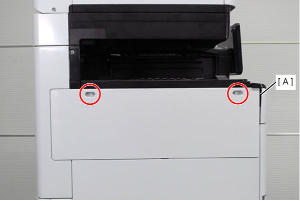
 : 3x10DW
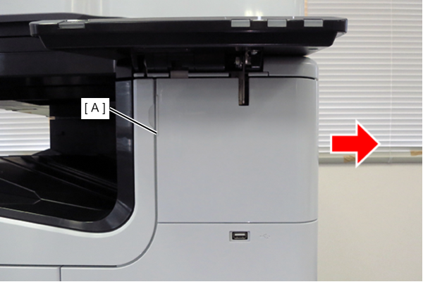
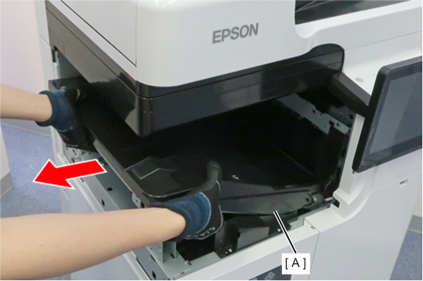
- Slide the front decorative cover upper (A) in the direction of the arrow to remove it.
- Remove one screw, and remove the front cover upper (A) in the direction of the arrow while pressing the hook.
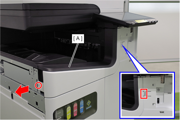
- : 3x10DW
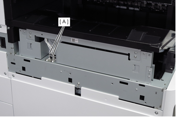
- Remove the two cables (A) from the connectors.
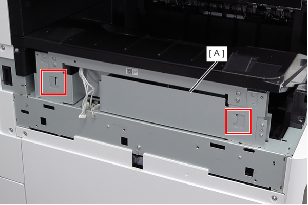
- Lift the FD frame (A), release the two hooks, and remove it to the left side of the product.
- Remove the screw that secures the ground wire (A).
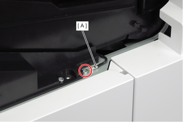
- : 3x8D
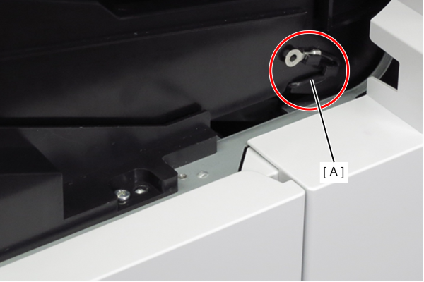
- Route the ground wire (A) around the guide.
- Remove the 4 screws that secure the FD stacker Assy (A).
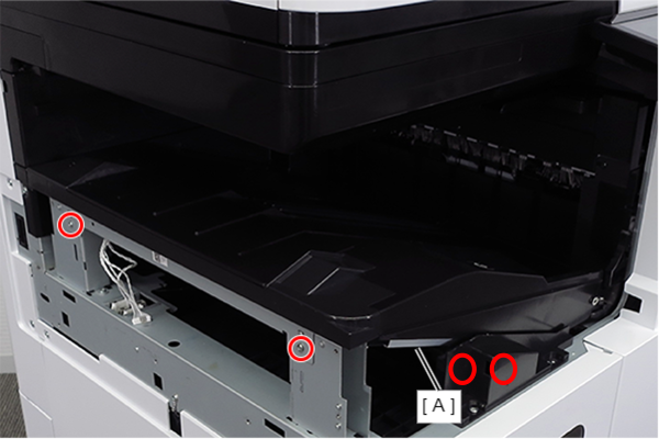
- : 3x8D
- Hold the position shown in the figure and remove the FD stacker Assy (A).
 Assembly / 組み立て
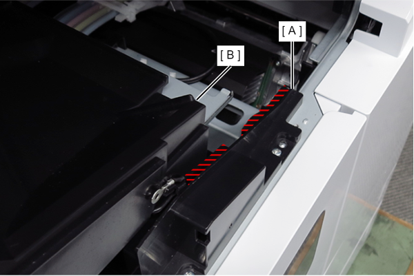
Attach the FD stacker Assy (B) along the rail of the FD stacker guide (A).
- Remove 1 screw, slide the FD inner cover lower (A) in the direction of the arrow, release the 2 hooks, and remove it.
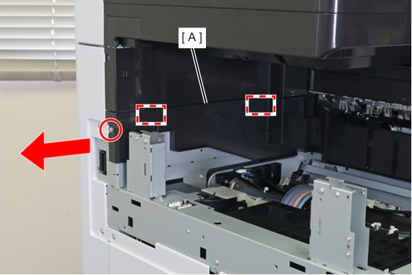
- : 3x8DW
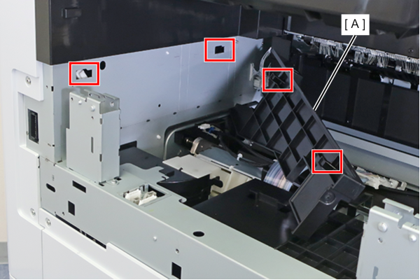
Assembly / 組み立てAlign the 2 hooks with the 2 holes in the body frame, and attach the FD inner cover lower (A).
Prepare the protective material (for temporary placement of the Head Unit) included with the Wiper Carriage Assy.
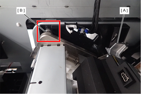
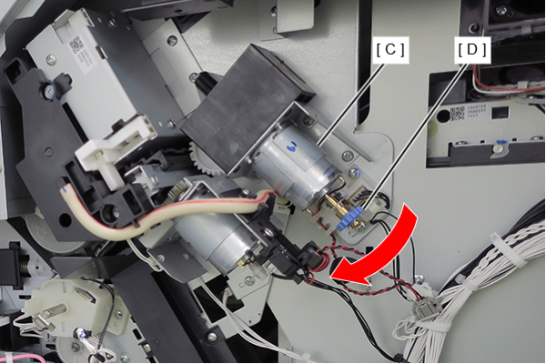
- Rotate the gear (D) of the Head Lifting Motor Assy (C) in the direction of the arrow until the bearing (B) of the Head Unit (A) is visible from the guide rail.
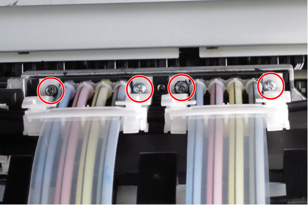
- Loosen the 4 screws that secure the ink supply tubes of the printhead.
 Assembly / 組み立て
If there is ink on the product during assembly, wipe it off with cloth etc.
 Check Point / チェックポイント
The four screws that secure the ink supply tubes cannot be removed because they have retaining parts.
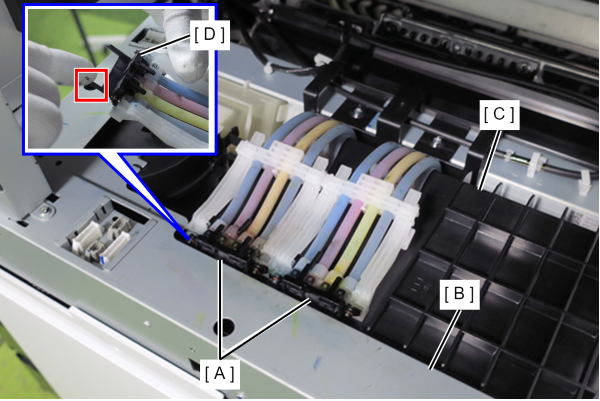
Attach two protective caps (A) to the connection parts of the ink supply tubes.
Note / 補足- Attach the protective cap as shown below.

- Insert the ink tube (A) into the frame (B) and FD cover (C).
Hang the protective cap (D) on the FD cover (C) and secure the ink tube (A).
 Check Point / チェックポイント
- Make sure that the FD cover tab (B) is inserted between the left and right ink tubes (A) shown in the figure below.
- A black protective cap is used in this manual, but a white protective cap is supplied at the repair site.
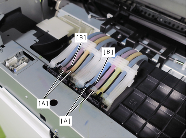
- Remove the cable (A) from the connector.
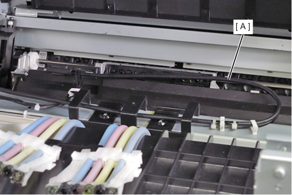
- Release the cable (A) from the two clamps and the guide.
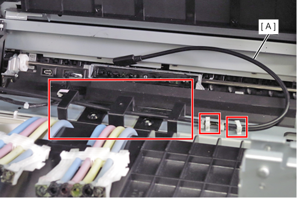 Assembly / 組み立て
- The Head USB Cable should be routed according to the following procedure.
- Straighten the head USB cable (A) and make sure it is not twisted.
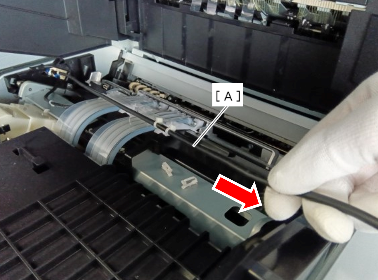
- Pass the Head USB cable through the guide and two clamps.
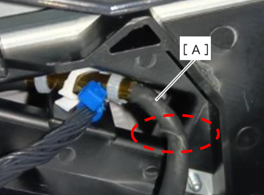
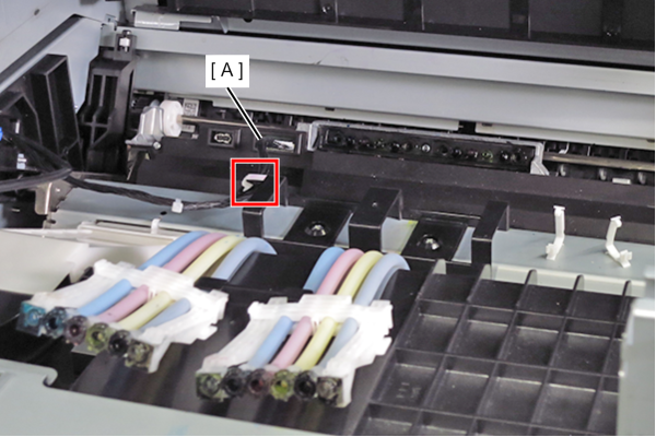
When doing this, align the triangle mark (A) stamped on the frame with the cable tie (C) of the cable (B).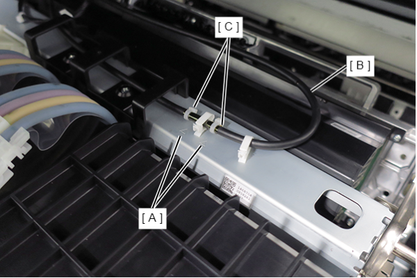
Straighten the Head USB cable again and make sure it is not twisted.
Connect the Head USB Cable to the connector and insert it into the hook.
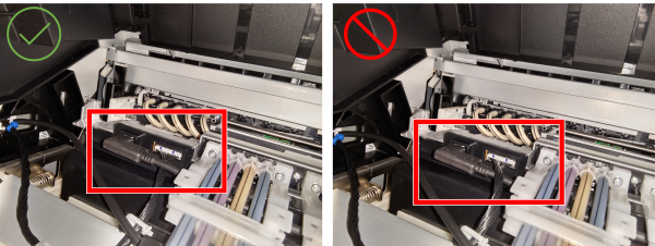
Caution / 注意- Make sure the Head USB Cable (A) is not twisted.
- If there is any twisting, the cable may break during product operation.
Place the USB cable on top of the harness.
* When the harness is on the top, stress is applied to the USB cable.
- Straighten the head USB cable (A) and make sure it is not twisted.
- The Head USB Cable should be routed according to the following procedure.
- Remove the cable (A) from the connector.
- Remove the cable (A) from the clamp.
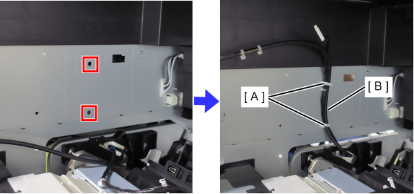
- Attach the clamp (A) included with the new head unit to the hole in the frame.
- Secure the two cables (B) to the clamps (A).
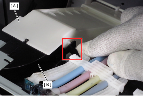
- Pull the lever to release the hook, slide the duct (A) in the direction of the arrow, and remove the duct (A) from the air port (B).
 Assembly / 組み立て
- If you forget to attach the duct, a Fatal Error will occur.
Re-disassembly is required to eliminate the fatal error, so be careful not to forget to install it.
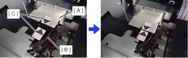
- When installing, make sure that the triangle marks on the labels affixed to the duct (A) and the air vent (B) match.
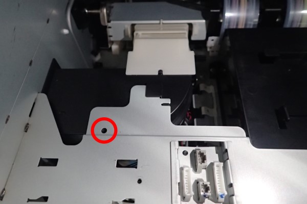
Note / 補足Depending on the time of manufacture, the duct is fixed with screws (no access required for repair).
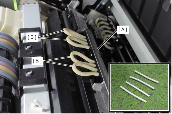
- To prevent ink leakage, attach the four tubes (B) included with the new head unit to the joints of the head unit (A).
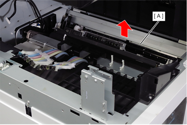
- Remove the head unit (A) upwards.
 Caution / 注意
- When removing the head unit, be careful not to splash ink on the head unit. Be especially careful not to get ink on the connector part (A) and around the joint (B).
- Check the following points when moving the head unit.
-
- Do not tilt the head unit left or right.
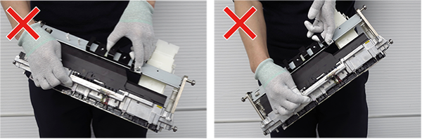
- Do not tilt the head unit forward or backward.
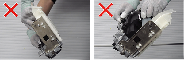
- Do not tilt the head unit left or right.
Check Point / チェックポイントHold the Head Unit with both hands as shown below.
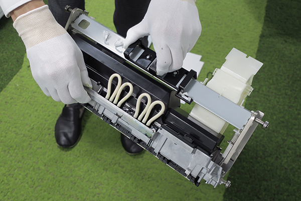 Assembly / 組み立て
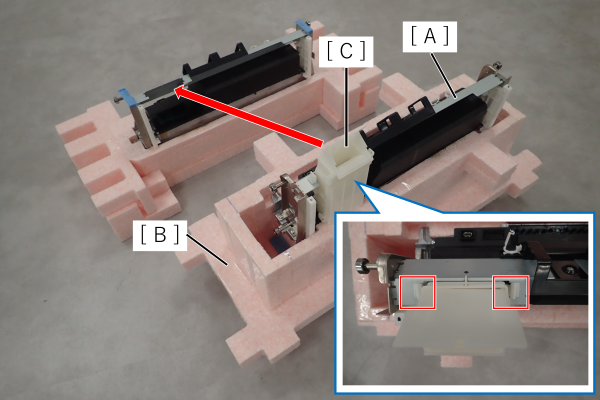
- Place the removed head unit (A) on the protective material (B) in which the new head unit was packed.
- Since the duct (C) is not included in the new head unit, replace the duct (C) of the removed head unit. Remove the duct (C) while pressing the two hooks.
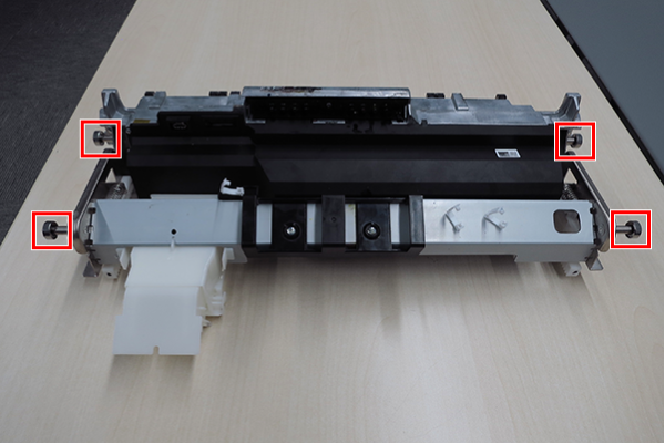
- The head unit must be installed by aligning the 4 bearings with the 4 rails on the main unit.
- Head unit bearings positions
- Main unit rails positions (front side)
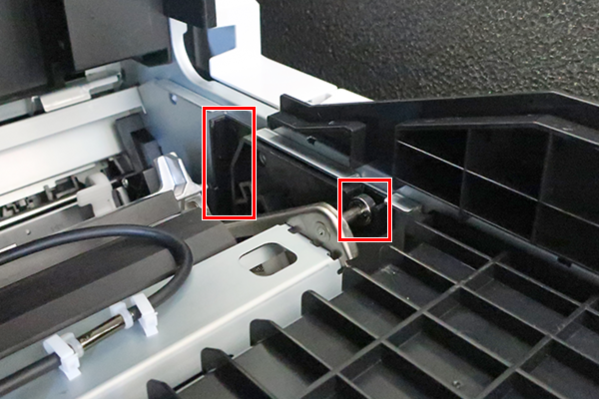
- Main unit rails positions (rear side)
Since it is difficult to see the position when installing, it is easier to align the position using the ruled lines (A) on the frame as a guide.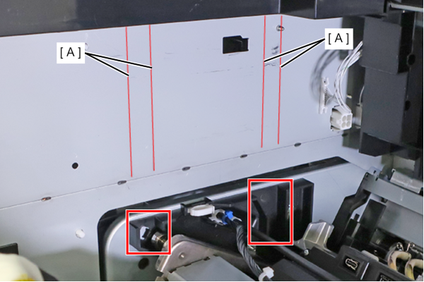
- When installing the head unit (A), align the head unit (A) with the angle of the FD stacker guide (B) and install it directly below. At this time, be careful not to damage the nozzle surface of the head unit (A).
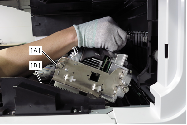
- Check that the head unit bearings are visible through the guide rails.
Front side (2 places)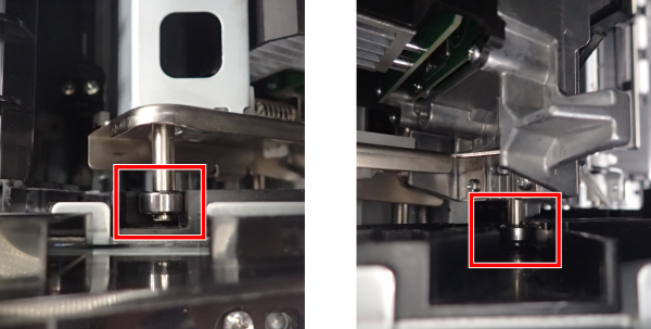
Rear side (1 place)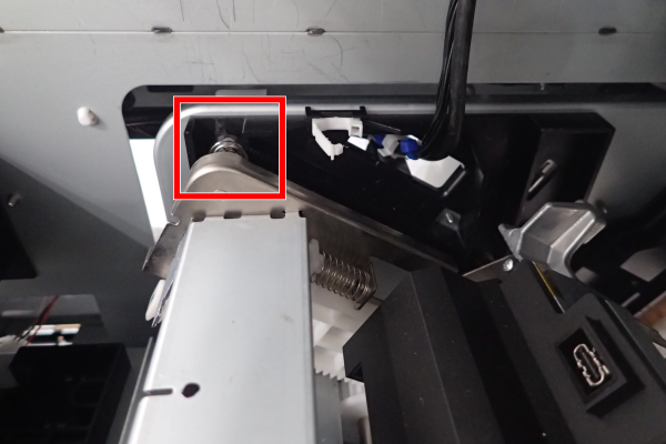
- Head unit bearings positions