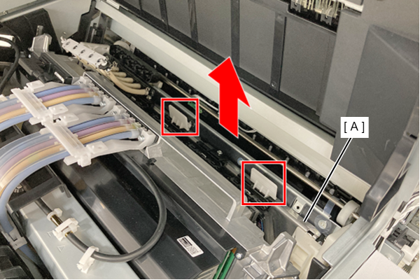
Pre-Replacement work cannot be performed (when the power cannot be turned on)
When replacing the head unit or ink system related parts of this product, it is necessary to drain the ink and moisturizing liquid and move to the parts replacement position.
Also, for components that have life counters, such as the Ink Supply Unit, it is necessary to reset the counters.
These operations can be performed using the pre-replacement menu (05 Adjustment for Replacement Part) in the Service Support mode, however, if the product cannot be turned on, the menu cannot be executed.
This section shows how to manually replace the target components when the pre-replacement menu cannot be executed, and lists the components that require resetting the life counter after replacement.
Components that require resetting of the lifetime counter
If any of the following parts have been replaced and the pre-replacement menu could not be executed, reset the life counter for that part in the 103 Counter Information menu.
- Cassette Pickup Roller (C1 / C2 / C3 / C4)
- Paper Tray Pickup Roller
- ADF Pickup Roller
- Belt Unit
- Ink Supply Unit
- Maintenance Unit
- Cap Unit
- Selector Unit
How to manually replace parts that cannot be replaced without running the pre-replacement menu
- Preparation for head unit replacement (move to replacement position)
- Preparing to replace the cap unit (moving to the replacement position)
 Caution / 注意 Caution / 注意 |
|
Preparation for head unit replacement (move to replacement position)
- Remove the 2 screws and remove the Left Cover Upper (A).
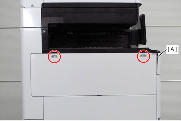
 : 3x10DW
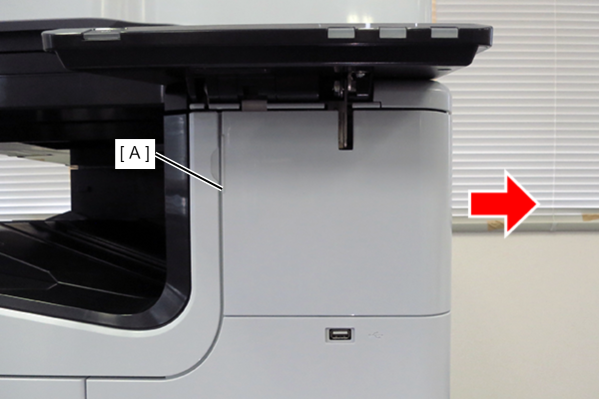
- Slide the front decorative cover upper (A) in the direction of the arrow to remove it.
- Remove one screw, and remove the front cover upper (A) in the direction of the arrow while pressing the hook.
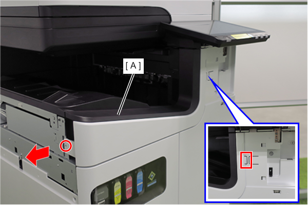
- : 3x10DW
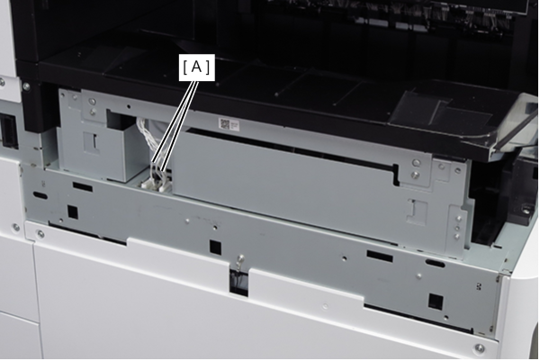
- Remove the two cables (A) from the connectors.
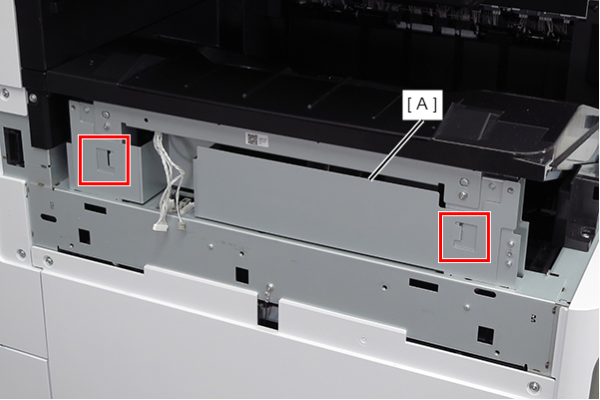
- Lift the FD frame (A), release the two hooks, and remove it to the left side of the product.
- Remove the screw that secures the ground wire (A).
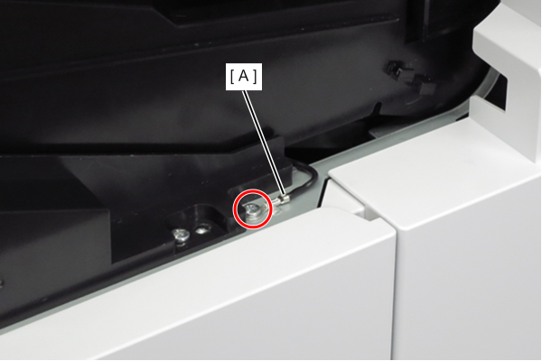
- : 3x8D
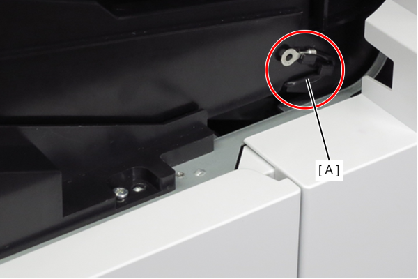
- Route the ground wire (A) around the guide.
- Remove the 4 screws that secure the FD stacker Assy (A).
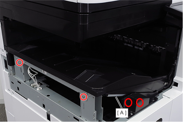
- : 3x8D
- Hold the position shown in the figure and remove the FD stacker Assy (A).
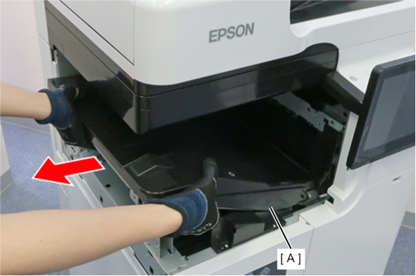
 Assembly / 組み立て
Attach the FD stacker Assy (B) along the rail of the FD stacker guide (A).
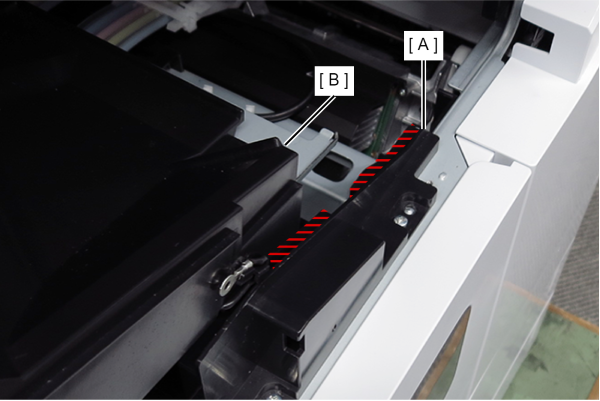
- Remove the 4 screws and remove the right cover sub (A).
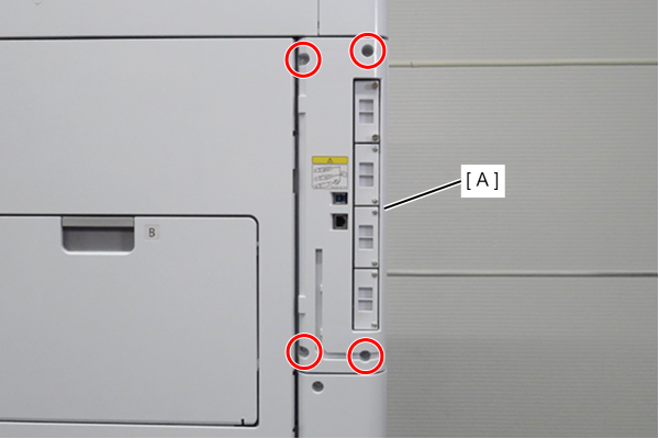
- : 3x10DW
- Remove 1 screw and slide the rear cover (A) in the direction of the arrow to remove it.
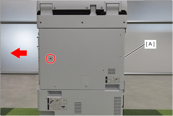
- : 3x10DW
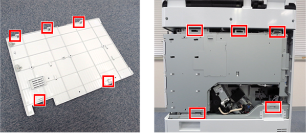
Assembly / 組み立てAlign the 5 hooks on the rear cover with the 5 holes on the main unit and attach it.
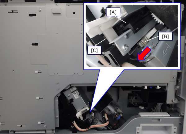
- Turn the drive gear (B) of the wiper Assy (A) forward to move the wiper assembly from inside the body to outside the frame.
 Check Point / チェックポイント
- Move the wiper Assy (A) until it contacts the lever (C) of the cleaner Assy.
- Depending on the condition of the product, it may not be necessary to move the wiper Assy.
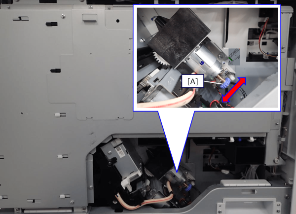
- Rotate the head drive motor dial (A) anticlockwise to move the head unit to the replacement position.
 Check Point / チェックポイント
The replacement position of the head unit is the state where the bearing of the head unit can be seen from the guide rail.
Front side (2 places)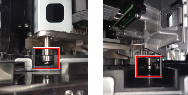
Rear side (1 place)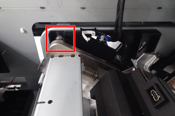
Preparing to replace the cap unit (moving to the replacement position)
Prepare for head unit replacement (move to replacement position).
- Remove Housing front lower (A) from the main unit.
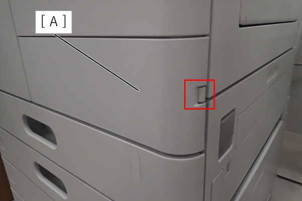
- Open the front cover (A).
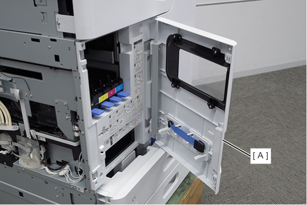
- Push the hook on the Front cover (A) and remove the Front cover (A).
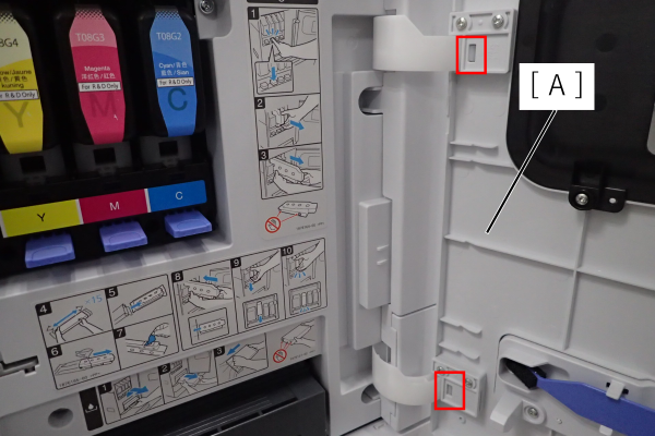
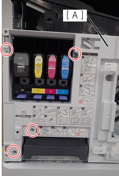
- Remove 6 screws and remove the Front right cover (A).
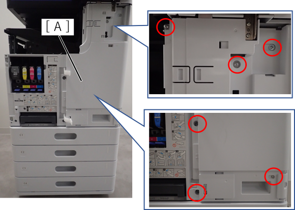
- Remove 4 screws and remove the Front left cover (A).
- Rotate the cap drive motor dial (A) clockwise (UP direction) to move the cap unit to the replacement position.
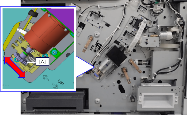 Check Point / チェックポイント
Replacement position of the cap unit is shown in the figure below.