
1st paper ejection guide Assy
- Remove the screw and remove polyester film upper plate Assy (A).
 Check Point / チェックポイント
- Depending on the options installed, the polyester film upper plate Assy may not be installed.
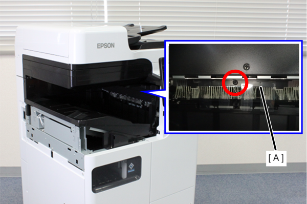
 3x8D/BK/P
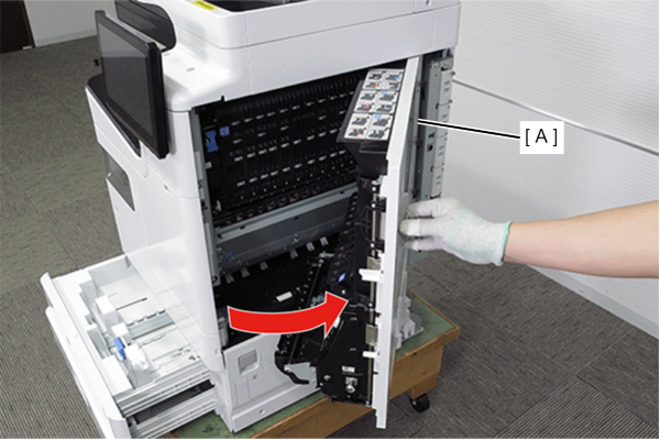
- Pull the lever to open the Right Door Unit (A).
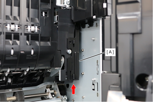
- Lift up to remove the middle door cable cover (A).
- Release the hook and remove the right door cable cover (A).
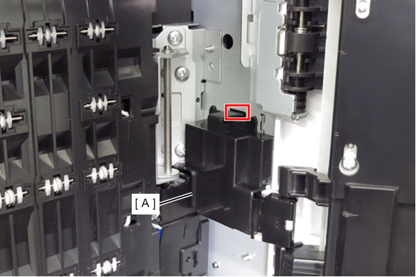
 Assembly / 組み立て
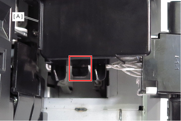
- Insert the tab of the right door cable cover (A) into the frame.
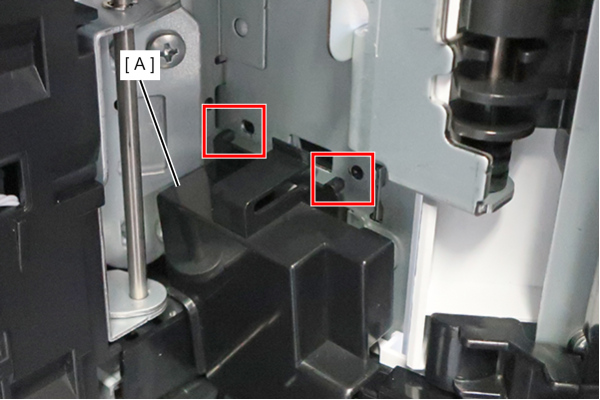
- Align the two dowels on the right door cable cover (A) with the two holes on the frame and install it.
Remove the cables from the 2 connectors.
 Note / 補足
- The cable colors are as follows:
- Upper side: black
- Lower side: white
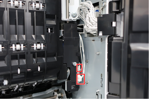
- The cable colors are as follows:
- Remove the 3 screws and remove the D3 Unit (A).
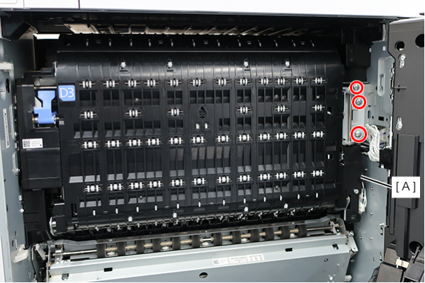
- : 4x8D/P
The steps below are different depending on what parts are installed.
Pre-ejection paper guide
1. Remove the 2 screws and remove the pre-ejection paper guide (A).
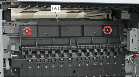
- : 3x5D/TBD
Floor Bridge Unit B
1. Remove the FB cable cover (A) by rotating it in the direction of the arrow while releasing the hook.
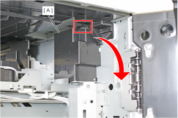
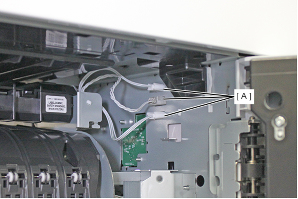
2. Disconnect the 3 cables of floor bridge unit B from the 3 connectors (A).
3. Remove the 2 screws of the floor bridge unit B (A).
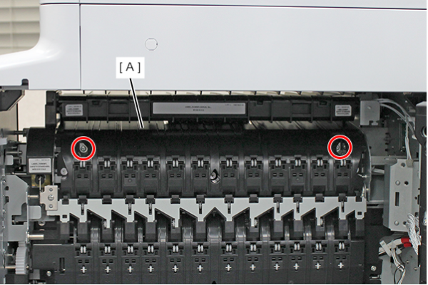
- : : 3x6D/P
4. Remove the 3 screws on the paper ejection side, and remove floor bridge unit B (A).
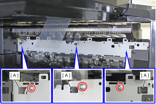
- : : 3x6D/P
- Remove the 2 screws and remove the Left Cover Upper (A).
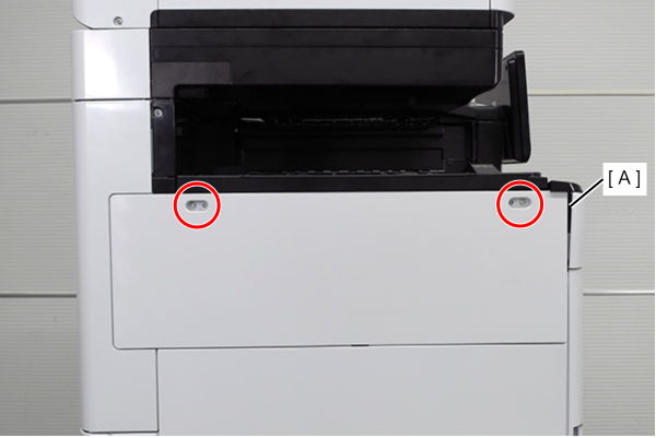
- : 3x10DW
- Remove the two screws and slide the Left Cover Sub Upper (A) in the direction of the arrow to remove it.
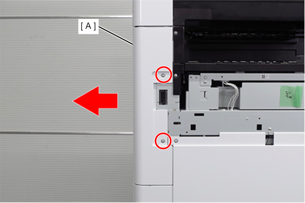
- : 3x10DW
- Remove the 4 screws and remove the right cover sub (A).
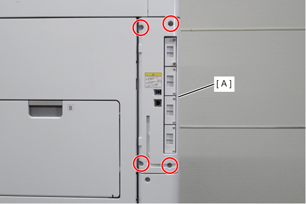
- : 3x10DW
- Remove 1 screw and slide the rear cover (A) in the direction of the arrow to remove it.
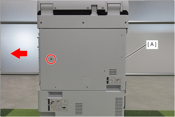
- : 3x10DW
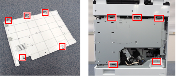
Assembly / 組み立てAlign the 5 hooks on the rear cover with the 5 holes on the main unit and attach it.
- Remove 4 screws.
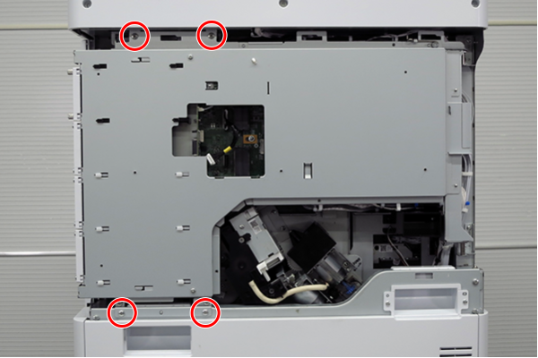
- : 4x8D
- Slightly lift the board box (A) to release the hook.
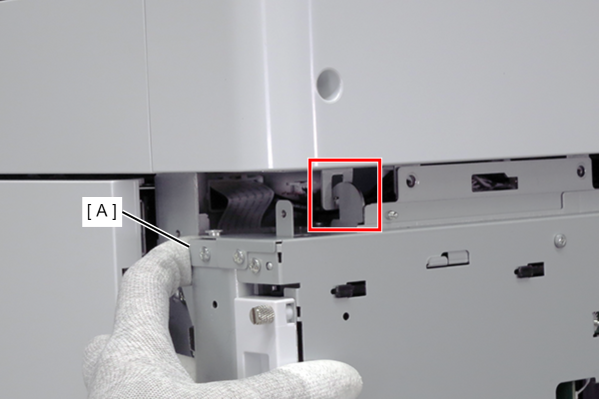
- Open the board box (A).
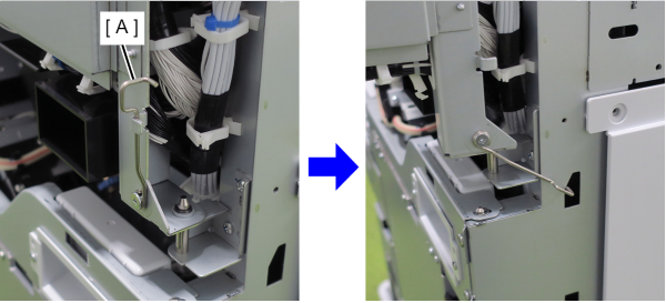
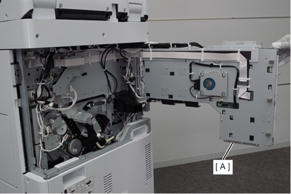 Check Point / チェックポイント
- By hooking the hook (A) of the board box to the hole in the main body, the position of the board box is stabilized, making it easier to work.
- Do not close the circuit board box while hooking the hook (A) on the main unit. The frame may be deformed.
- Release the clamp (A).
Remove the FFC from the SCN relay board (B) and release the routing.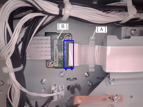
- Remove the 4 screws and slide the Ej drive train Assy (A) as shown in the below.
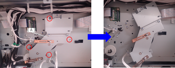
- 3X8D
- Remove the 4 screws and remove the middle door hold rear frame (A).
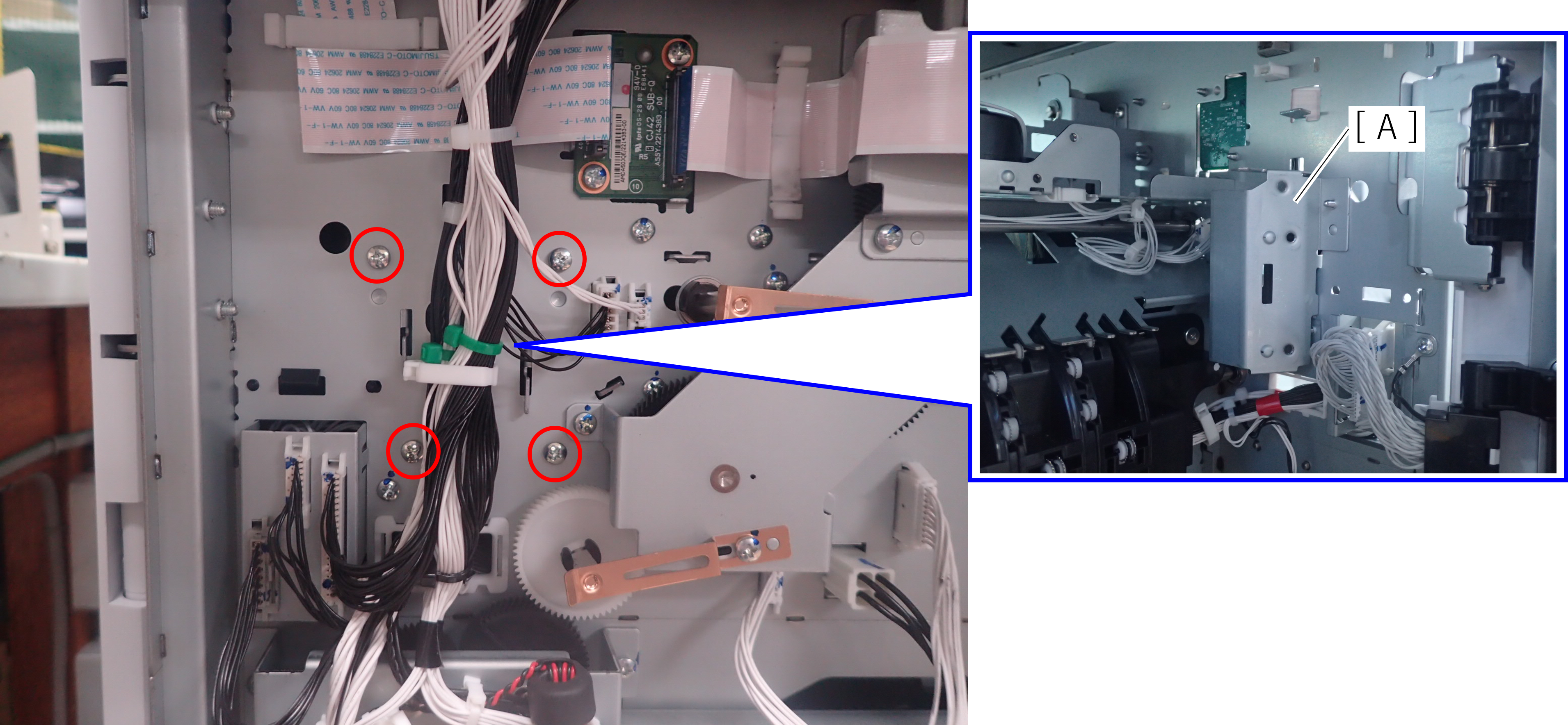
 : 3X8D
- Release the 2 dowels with a flathead screwdriver and remove the Front Cover (A).
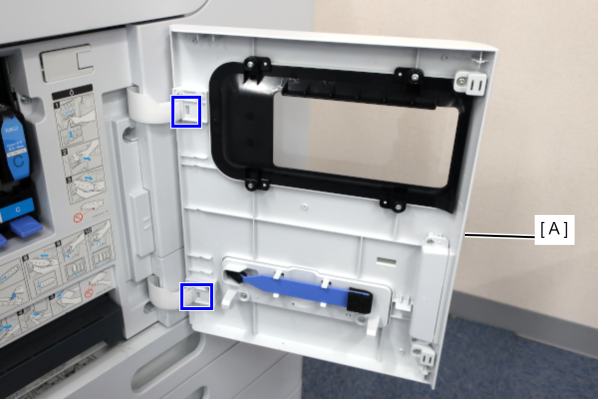
- Remove one screw, and remove the front cover upper (A) in the direction of the arrow while pressing the hook.
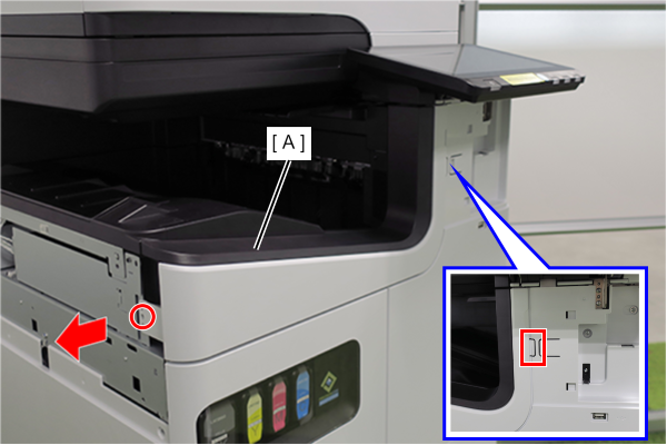
- : 3x10DW
- Slide the front decorative cover upper (A) in the direction of the arrow to remove it.
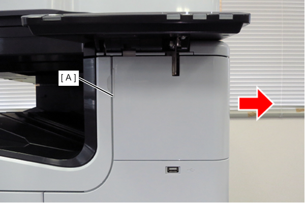
- Release the hook and remove the Front Decorative Cover Lower (A) in the direction of the arrow.
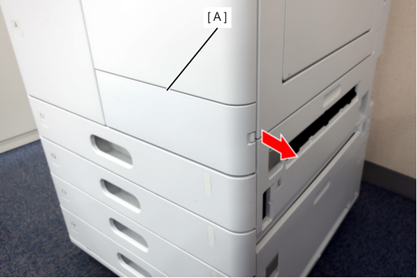
- Remove 6 screws and remove the Front Right Cover (A).
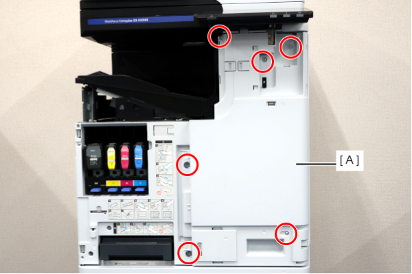
- : 3x10DW/P
- Release the clamps.
Remove the E-ring (A) and remove the 1st paper ejection roller speedup clutch (B) from the 1st paper ejection roller shaft.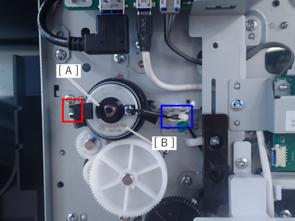 Assembly / 組み立て
Set the concave part of the FD clutch (A) to the protrusion on the main unit.
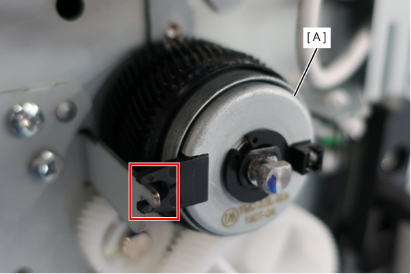
- Remove the 3 screws and remove the Middle door hold front frame (A).
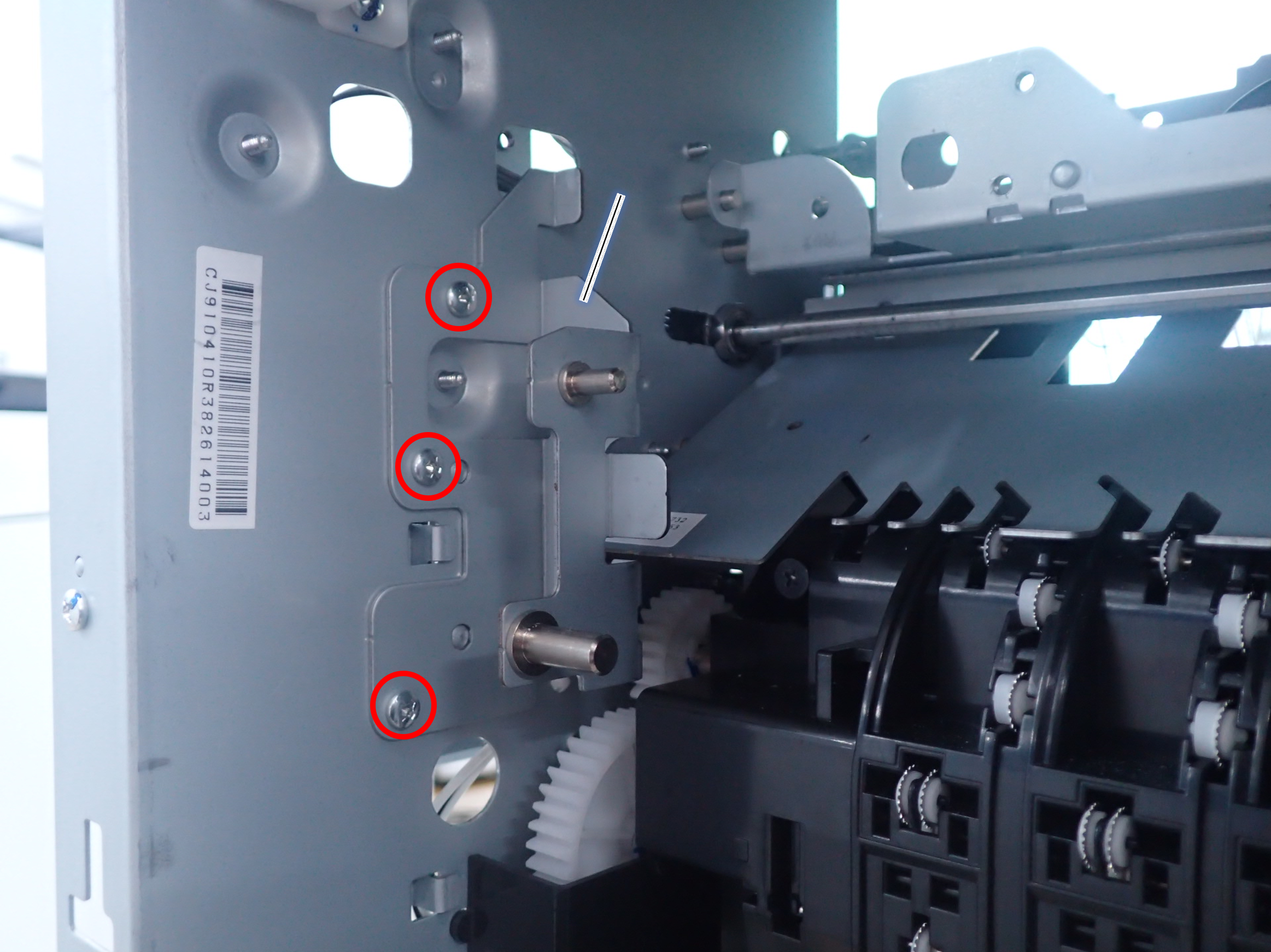
 : 3X8D
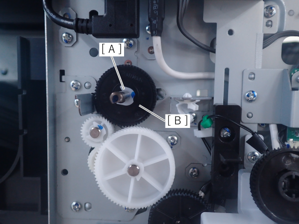
- Remove the E-ring (A) and remove the 1st paper ejection roller gear (B) from the 1st paper ejection roller shaft.
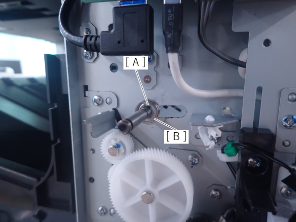
- Remove the E-ring (A) and remove the bearing (B) from the 1st ejection roller on the front side.
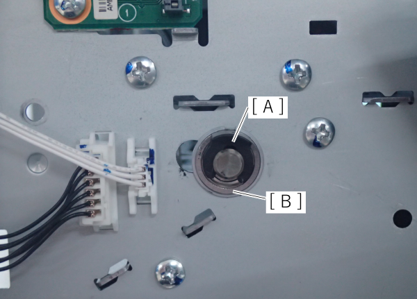
- Remove the E-ring (A) and remove the bearing (B) from the 1st ejection roller on the rear side.
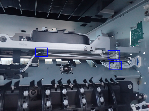
- Release the 3 clamps and release the cables.
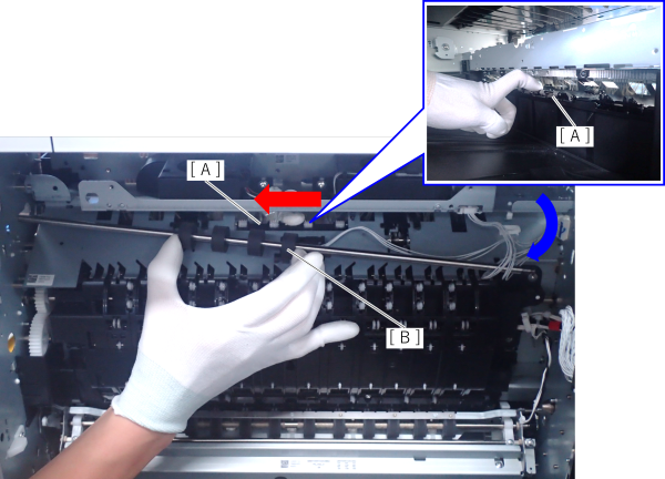
- While holding down the driven roller (A) from the paper ejection side with your hand, slide the 1st paper ejection roller (B) in the direction of the red arrow, then remove it in the direction of the blue arrow.
 Check Point / チェックポイント
- When disassembling and reassembling the 1st ejection roller, holding the sides of the roller makes it easier to operate but increases the risk of foreign substance and dirt adhering to the roller surface.
Check after reassembly and clean if necessary.
- When disassembling and reassembling the 1st ejection roller, holding the sides of the roller makes it easier to operate but increases the risk of foreign substance and dirt adhering to the roller surface.
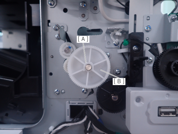
- Remove the E-ring (A) and remove the EJ compound gear (B).
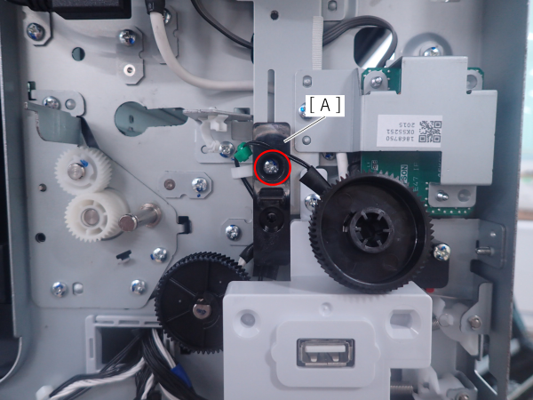
- Remove the screw and remove the USB lock (A).
- 3x8D
- Remove the 2 screws, slide the 2 swage shafts (A) forward to remove them.
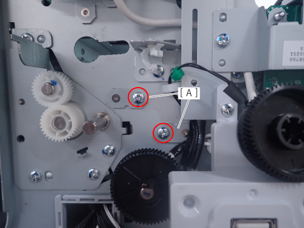
- 3X8D
- Remove the 2 screws of the 1st paper ejection guide Assy on the rear side of the printer.
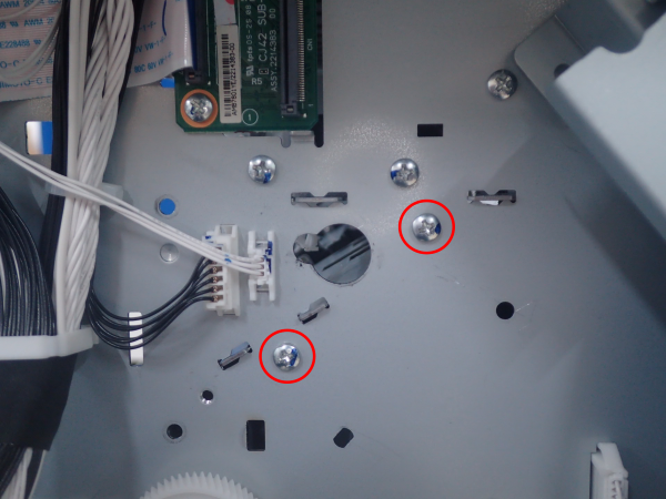
- 3X8D
- Disconnect the 1st pre-ejection sensor cable from the connector (A) on the paper ejection side.
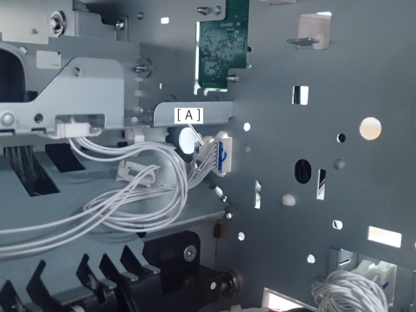
- While holding down the driven roller (A) from the paper ejection side with your hand, slide the 1st paper ejection guide Assy (B) in the direction of the red arrow, then remove it in the direction of the blue arrow.
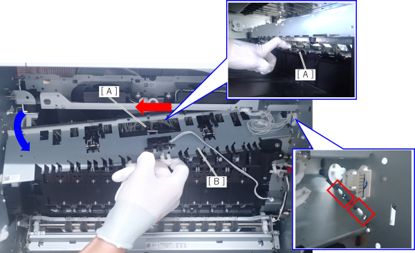 Assembly / 組み立て
- When reassembling, be careful not to break or damage the anti-static brush.