
Shift Arm Unit
- Refer to the following and remove the floor finisher from the printer main unit.
Floor Finisher Installation Procedure
 Caution / 注意
- When disconnecting the Floor Finisher from the Main Unit, the power of the Main Unit must be turned off.
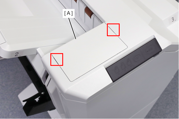
- Using a flathead screwdriver, release the hooks (x2) on the top small cover and front (A).
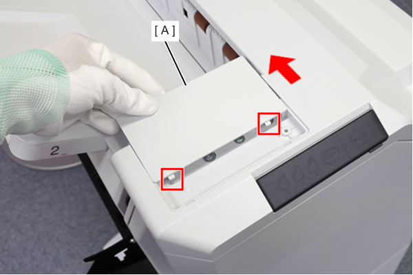
- Slide the small top cover front (A) in the direction of the arrow to release the tabs (x2) and remove the cover.
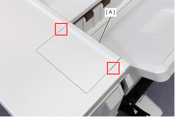
- Using a flathead screwdriver, release the hooks (x2) on the small top cover and rear (A).
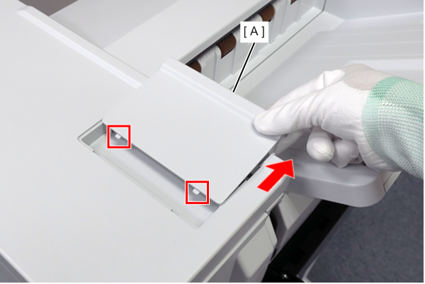
- Slide the small top cover rear (A) in the direction of the arrow to release the tabs (x2) and remove it.
Remove 4 screws of the Top Cover (A).
Release the hook (x2) and lift the Top Cover (A).
- Disconnect the cable (C) from the connector (B) and remove the Top Cover (A).
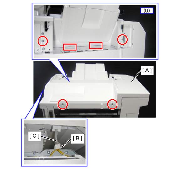
 : 4x10DC
Remove 1 screw of the Rear Cover, Sub (A).
- Put your finger on the recess of the rear cover, sub (A) and open it to the left to remove it.
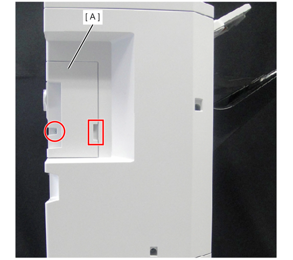
- : 4x10DC
Remove 3 screws of the Rear Cover, Upper (A).
- Slightly raise the top cover (B) and remove the rear cover, upper (A).
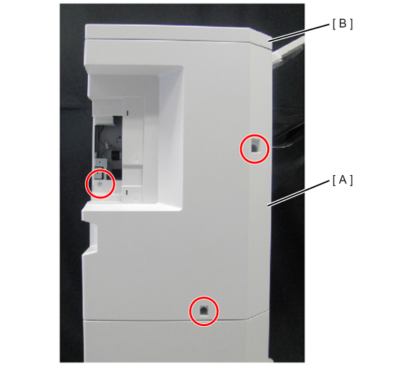
- : 4x10DC
Release the cables (x2) (A) from the clamps (x2).
- Disconnect the cables (x3) (A) (C) from the connectors (x3) (B).
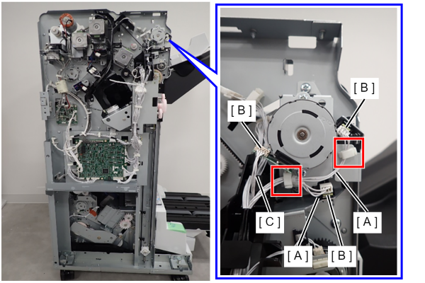
- Remove the 2 screws and remove the FIN Shift Arm Release Motor (A) upwards.
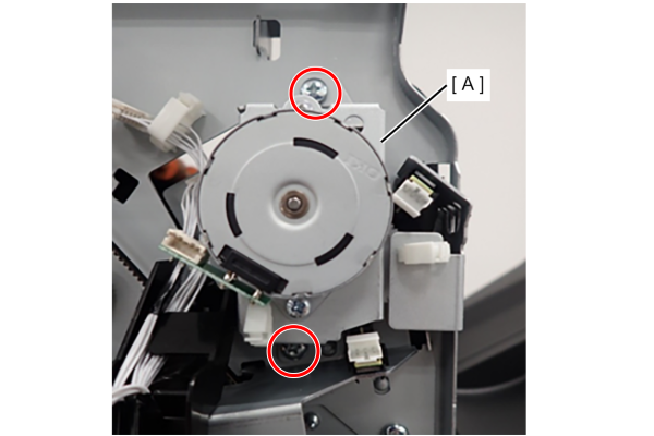
- : 4x8D/P
- Remove 1 screw and remove the FIN Shift Arm Release Position HP Sensor (A).
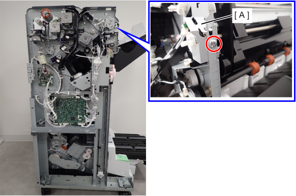
- : 4x8D/P
Open the front cover (A).
- Remove the screw that secures the belt (B).
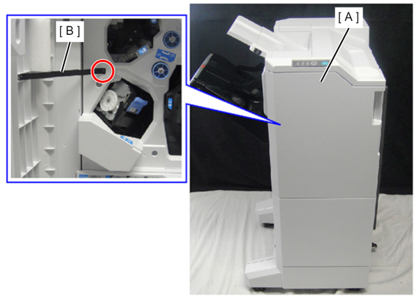
- : 3x8DC/BK
- Remove one screw and slide the cover hinge (A) upward to remove it.
- Remove the front cover (B).
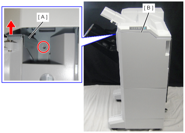
- : 4x8D/P
- Remove one screw and remove the front cover lower (B) and washer (A).
- Remove the washer (A).
- Remove the front cover lower (B).
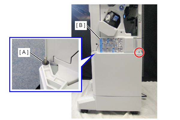
- : 4x10DC
- Remove 3 screws and the Front Inner Cover, Upper (A).
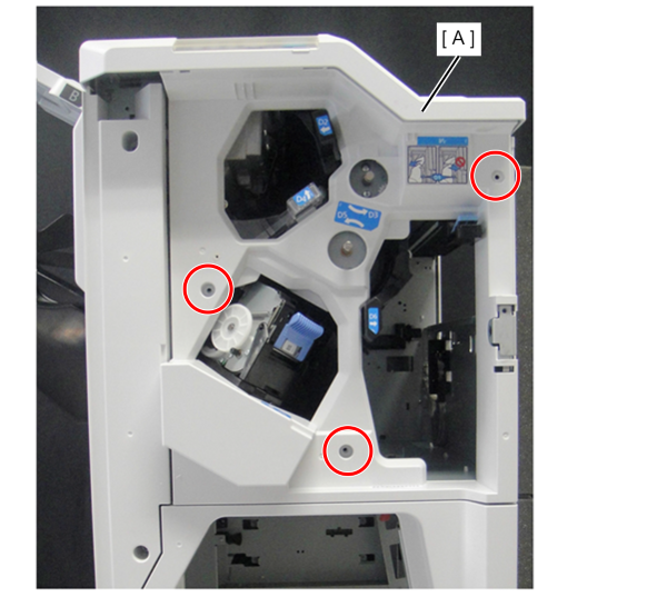
- : 4x10DC
- Remove the one screw.
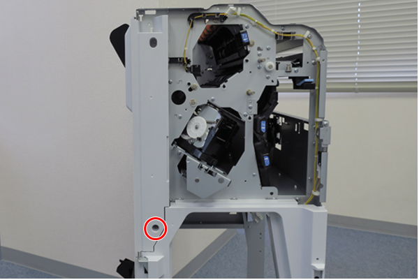
- : 4x10DC
Slightly lift the front inner cover sub (A) to release the hook and remove it.
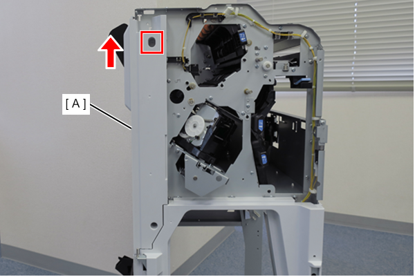
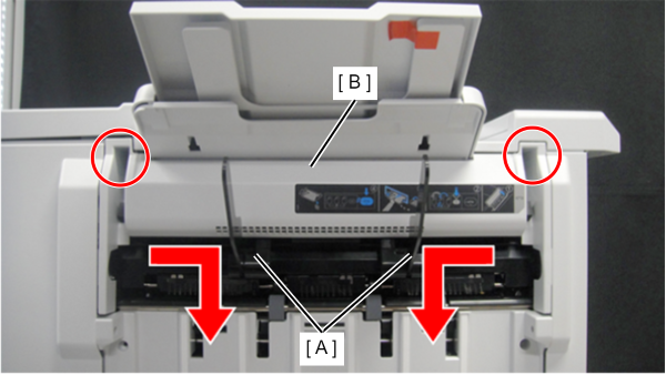
- Move the paper holding lever (A) to the center and point it downward.
- Remove the 2 screws.
- Remove the Lower Paper Ejection Cover (B).
 : 4x8D/P
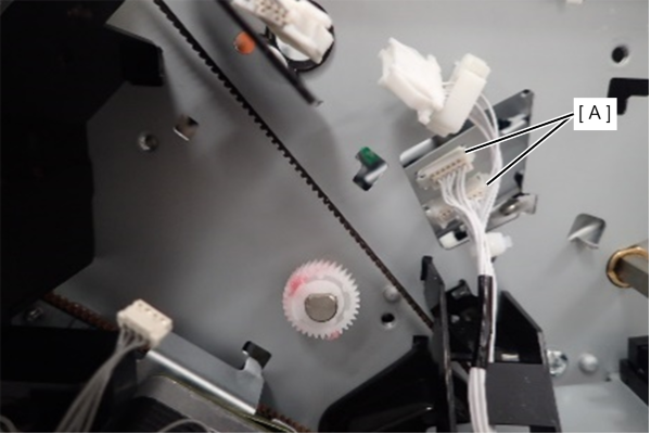
- Remove the cable (x2) (A) from the connector on the rear side.
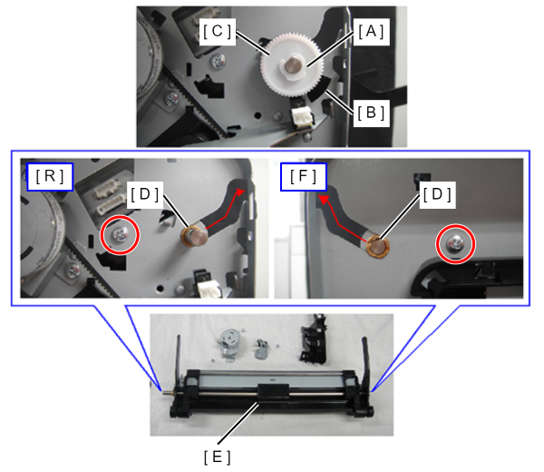
- Remove the plastic E-ring (A), and remove the sensor pulley (B) and the gear (C).
- Remove the 2 screws.
- Slide the bearing (D) along the groove in the frame and remove the shift arm unit (E).
- : 4x8D/P
 Assembly / 組み立て
- Check the following points when installing the shift arm unit.
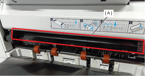
- Is the cover (A) shown in the figure below in the outside position?
- Is the interlock switch (A) pushed by the shift arm unit (B)?
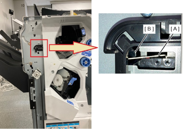
- Is the cover (A) shown in the figure below in the outside position?