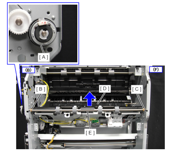
Lower Paper Eject Roller
- Refer to the following and remove the floor finisher from the printer main unit.
Floor Finisher Installation Procedure
 Caution / 注意
- When disconnecting the Floor Finisher from the Main Unit, the power of the Main Unit must be turned off.
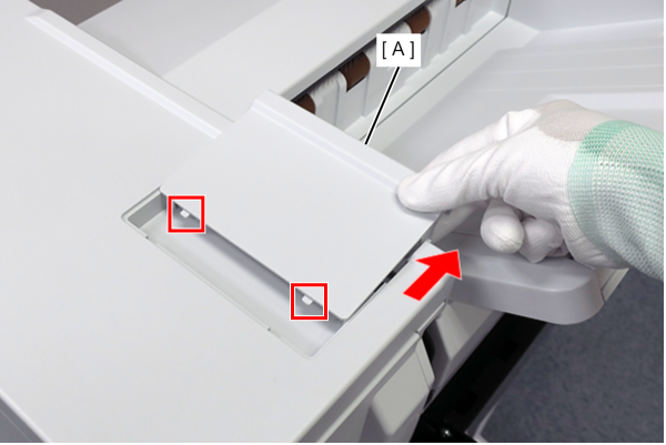
- Using a flathead screwdriver, release the hooks (x2) on the top small cover and front (A).
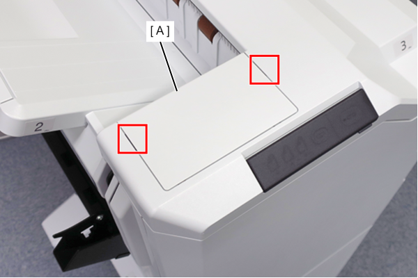
- Slide the small top cover front (A) in the direction of the arrow to release the tabs (x2) and remove the cover.
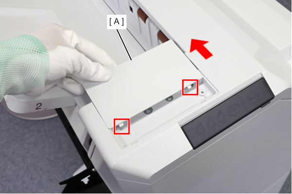
- Using a flathead screwdriver, release the hooks (x2) on the small top cover and rear (A).
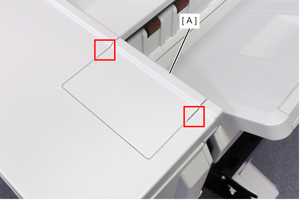
- Slide the small top cover rear (A) in the direction of the arrow to release the tabs (x2) and remove it.
Remove 4 screws of the Top Cover (A).
Release the hook (x2) and lift the Top Cover (A).
- Disconnect the cable (C) from the connector (B) and remove the Top Cover (A).
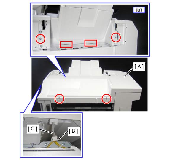
 : 4x10DC
Remove 4 screws.
Disconnect the cable (A) from the connector.
- Remove the Upper Paper Eject Feed Sub-roller Unit (B).
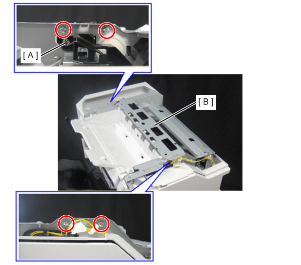
- : 4x8D/P
- Remove the two screws and tilt the lower document ejection cover (A).
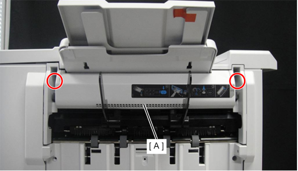
- : 4x10DC
- Open the T1 door (A) and open the jam clearing guide T3 (B).
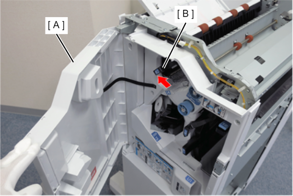
- Remove the cable (A) from the relay connector on the left side of the product.
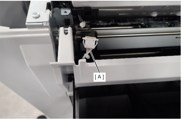
- Remove the cables (x2) (A) from the relay connectors (x2) on the rear side of the product.
- Pass the cables (x2) (A) through the hole (B).
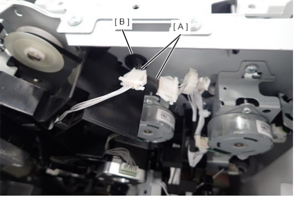
- Remove 4 screws.
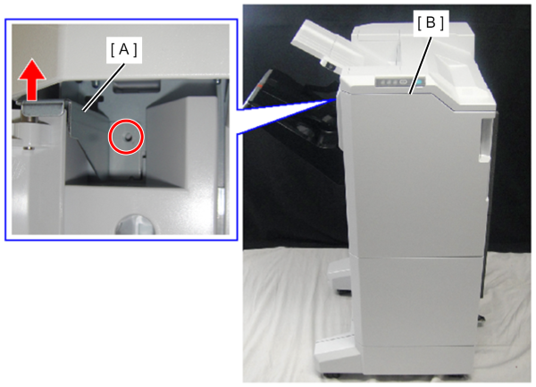
- : 4x10DC
Detach the upper document ejection tray base (B) while bending the lower document ejection cover (A) in the direction of the arrow.
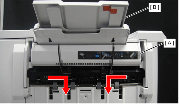
- Close the T3 jam release guide (A).
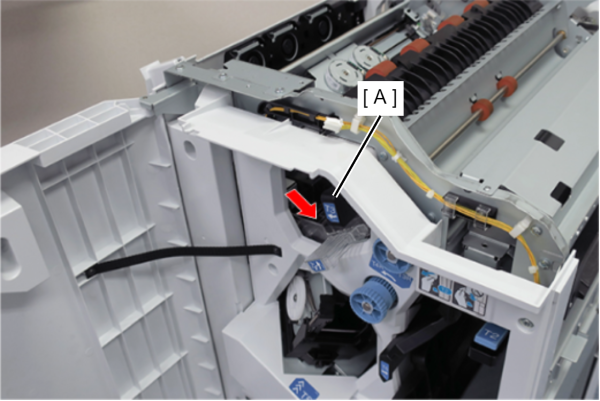
- Remove the guide open/close spring (A) from the screw foot.
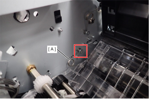
- Release the dowel on the back side of the D4 jam release guide (A) using a flat-blade screwdriver etc.
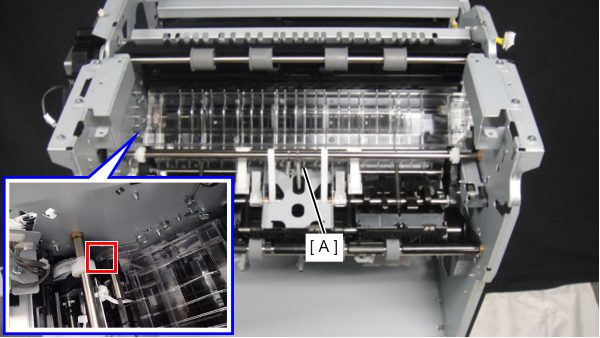
- Release the dowel on the front side and remove the D4 jam release guide (A).
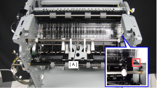
Remove 1 screw of the Rear Cover, Sub (A).
- Put your finger on the recess of the rear cover, sub (A) and open it to the left to remove it.
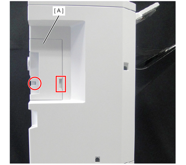
- : 4x10DC
Remove 3 screws of the Rear Cover, Upper (A).
- Slightly raise the top cover (B) and remove the rear cover, upper (A).
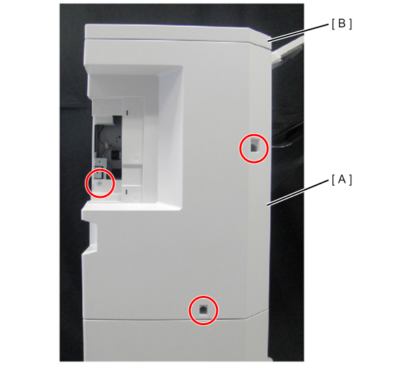
- : 4x10DC
- Remove 2 screws and remove the Rear Cover, Lower (A).
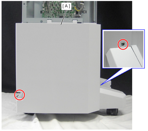
- : 4x10DC
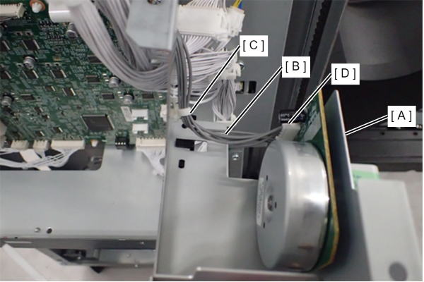
Remove the cable (A) from the connector.
- Remove the 2 screws and remove the FIN Bundle Ejection Unit Drive Motor (B).
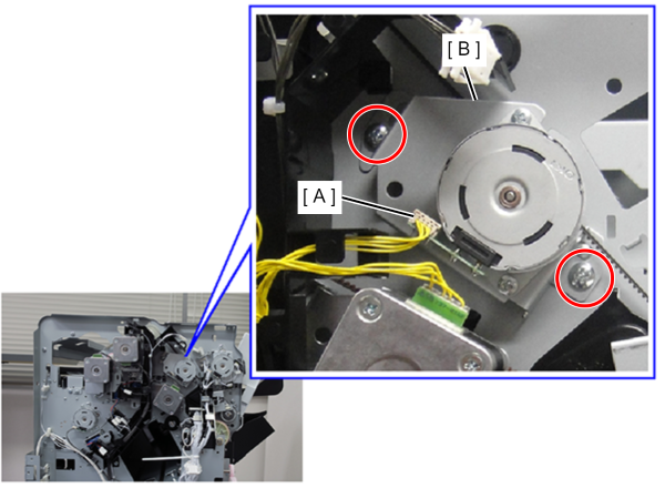
- : 4x8D/P
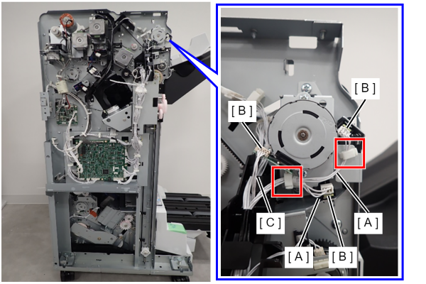
Release the cables (x2) (A) from the clamps (x2).
- Disconnect the cables (x3) (A) (C) from the connectors (x3) (B).
- Remove the 2 screws and remove the FIN Shift Arm Release Motor (A) upwards.
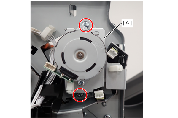
- : 4x8D/P
- Remove 1 screw and remove the FIN Shift Arm Release Position HP Sensor (A).
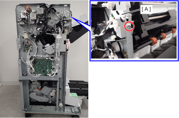
- : 4x8D/P
Open the front cover (A).
- Remove the screw that secures the belt (B).
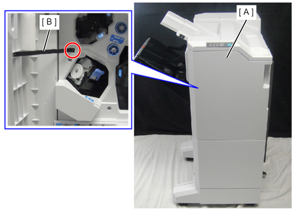
- : 3x8DC/BK
- Remove one screw and slide the cover hinge (A) upward to remove it.
- Remove the front cover (B).
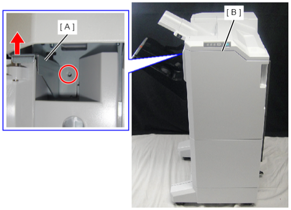
- : 4x8D/P
- Remove one screw and remove the front cover lower (B) and washer (A).
- Remove the washer (A).
- Remove the front cover lower (B).
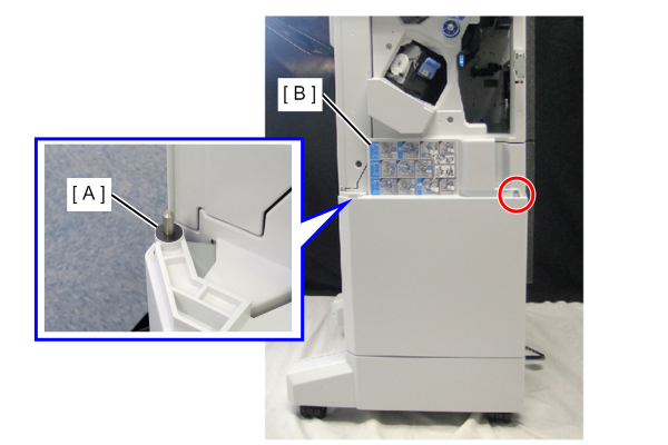
- : 4x10DC
- Remove 3 screws and the Front Inner Cover, Upper (A).
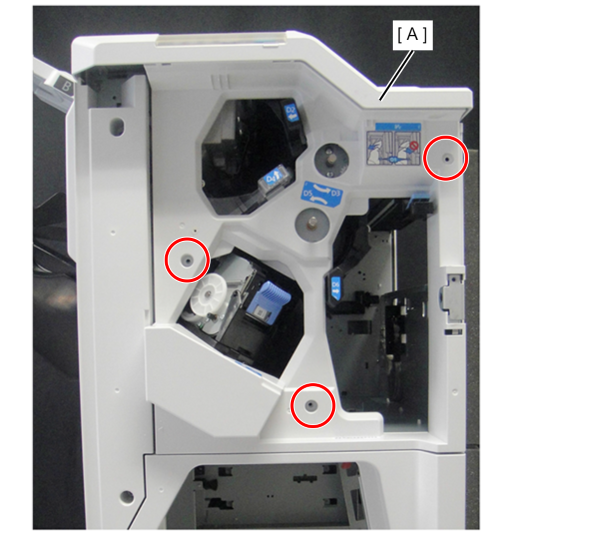
- : 4x10DC
- Remove the one screw.
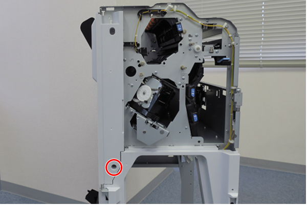
- : 4x10DC
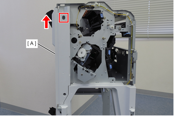
Slightly lift the front inner cover sub (A) to release the hook and remove it.
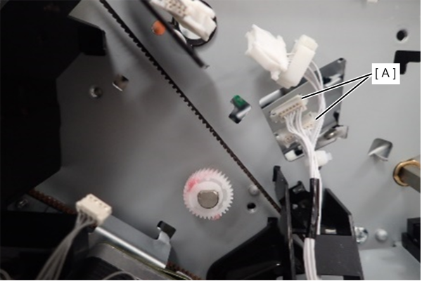
- Remove the cable (x2) (A) from the connector on the rear side.
- Remove the plastic E-ring (A), and remove the sensor pulley (B) and the gear (C).
- Remove the 2 screws.
- Slide the bearing (D) along the groove in the frame and remove the shift arm unit (E).
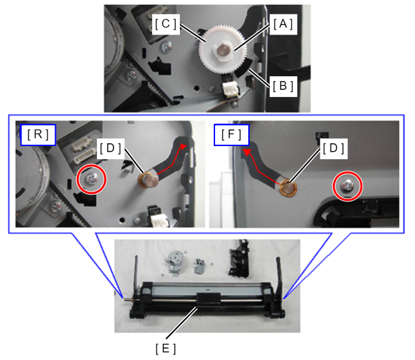
- : 4x8D/P
 Assembly / 組み立て
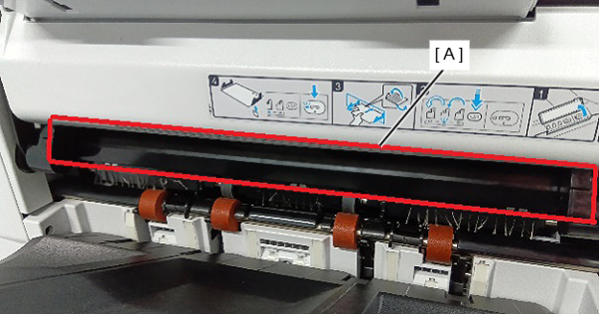
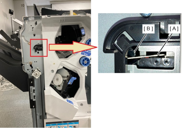
- Check the following points when installing the shift arm unit.
- Is the cover (A) shown in the figure below in the outside position?
- Is the interlock switch (A) pushed by the shift arm unit (B)?
- Is the cover (A) shown in the figure below in the outside position?
Remove 4 screws.
- Slightly lift the front inner cover bottom (A) to release the hook.
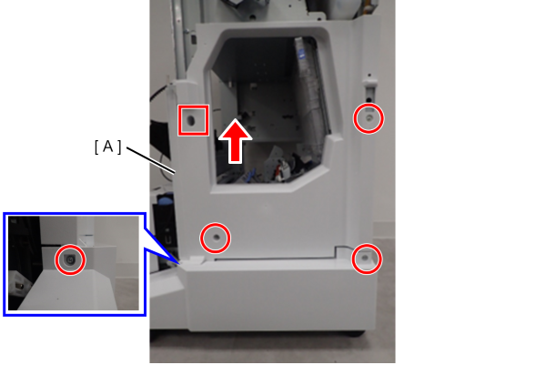
- : 4x10DC
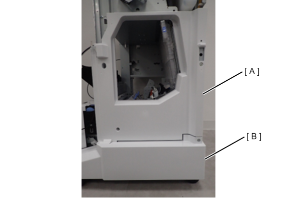
- Remove the lower front inner cover (A) and the front caster cover (B).
 Assembly / 組み立て
- Insert the shaft (B) into the hole of the lower front inner cover (A).
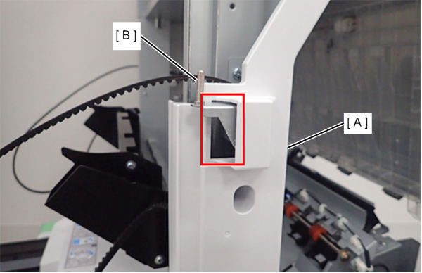
- Fit the hooks (x2) at the bottom of the front caster cover (A).
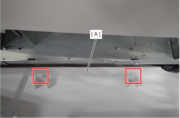
- After assembling the lower front inner cover (A) and the front caster cover (B), tighten the screws together.
- Insert the shaft (B) into the hole of the lower front inner cover (A).
- Remove one spring (B) from the bundle discharge unit lift up shaft (A).
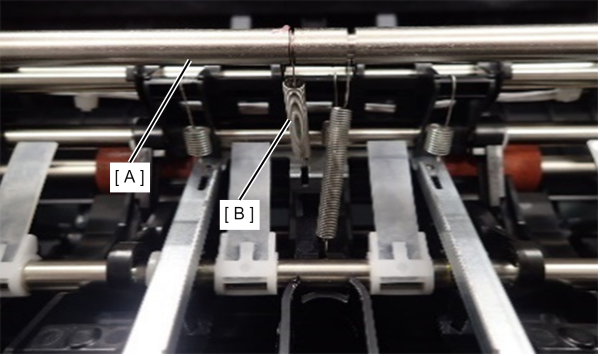
- To prevent the spring from being lost, hang the spring (A) on the shaft (B) on the bundle discharge unit side.
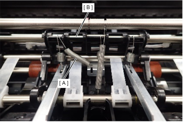
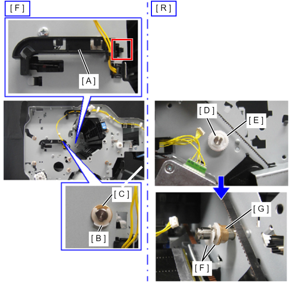
- Release the hook and remove the harness guide (A).
- Remove the plastic E-ring (B) and bearing (C) from the front side.
- On the back side, remove the plastic E ring (D) and remove the gear (E).
- On the back side, remove two plastic E-rings (F) and remove the bearing (G).
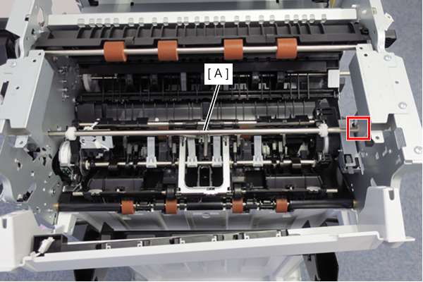
- Pull out the bundle discharge unit lift up shaft (A) from the hole on one side and remove it.
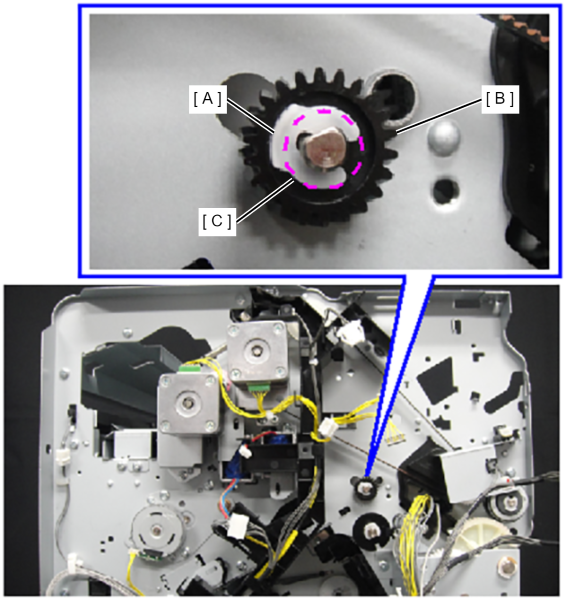
- Remove the plastic E-ring (A), the gear (B), and the bearing (C) on the back side.
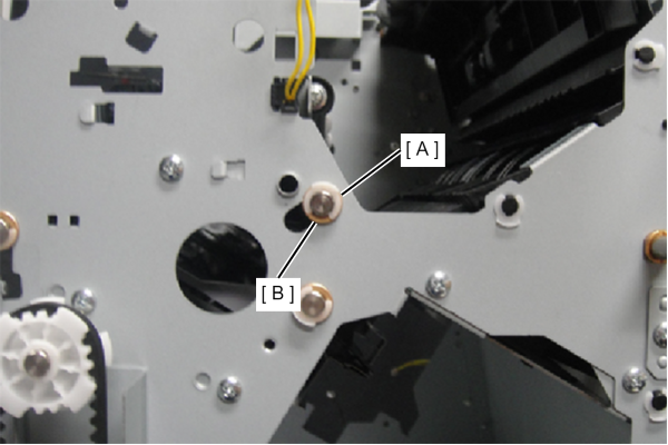
- Remove the plastic E-ring (A) and the bearing (B) from the front side.
- Remove 1 screw and disconnect the ground wires (x2) (A).
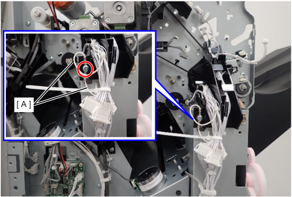
- : 4x8D/P
Assembly / 組み立てTighten the ground wires (x2) (A) together with the same screw.
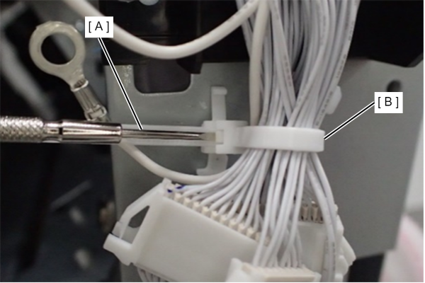
- Insert the precision screwdriver (A) and release the cable tie (B).
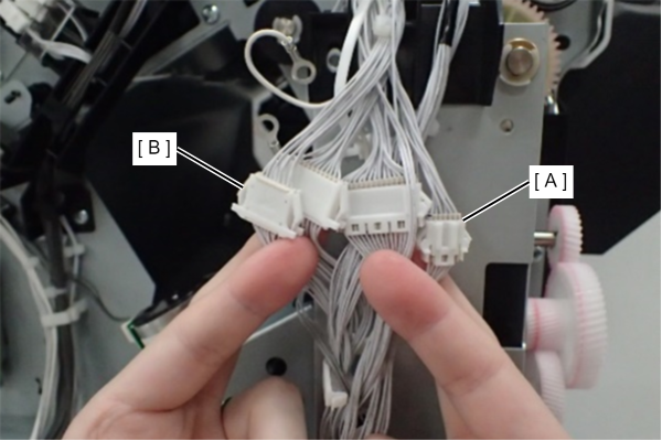
- Remove the two harnesses (3-cores (A) and 4-cores (B)) from the connector.
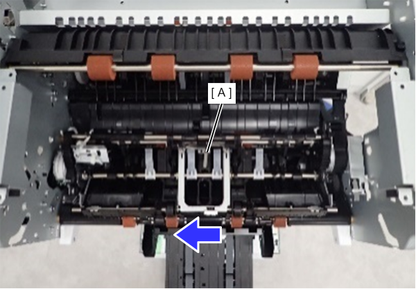
- Slide the upper unit (A) backward.
- Bend the front frame (A) and remove the shaft (C) from the shaft hole (B).
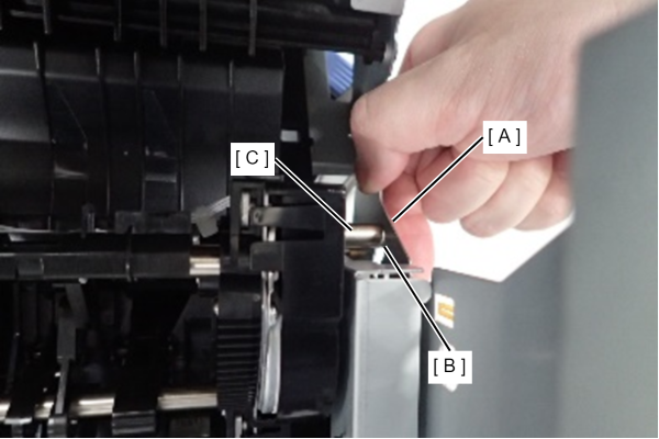
- Remove the shaft (B) from the shaft hole (A) on the rear side, and remove the upper unit (C).
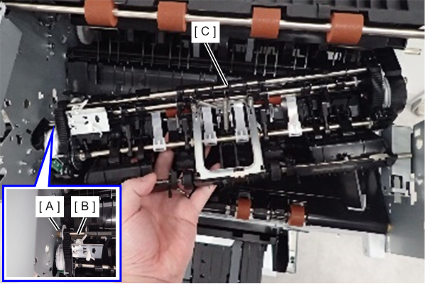
Disconnect the cable (A) from the connector.
- Remove one screw and remove the FIN Alignment Paddle HP Sensor (B).
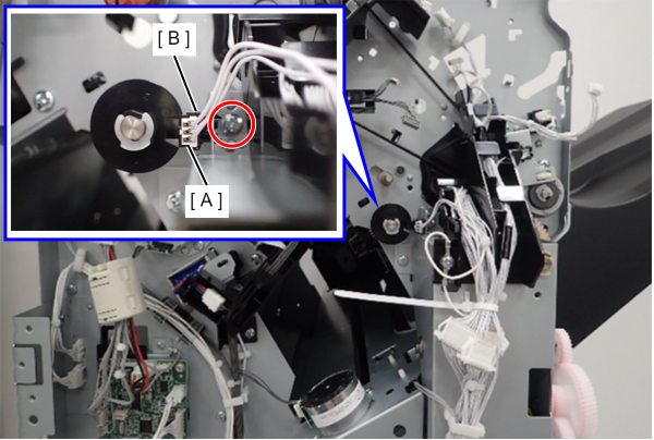
- : 4x8D/P
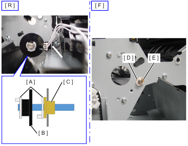
Remove two plastic E-rings (A), and remove the sensor wheel (B) and the bearing (C).
- Remove the plastic E-ring (D) and bearing (E) from the front side.
SX: ---
- Slide the paddle shaft assembly (A) to the rear side.
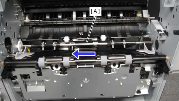
- Bend the front frame (A) and remove the shaft (C) from the shaft hole (B).
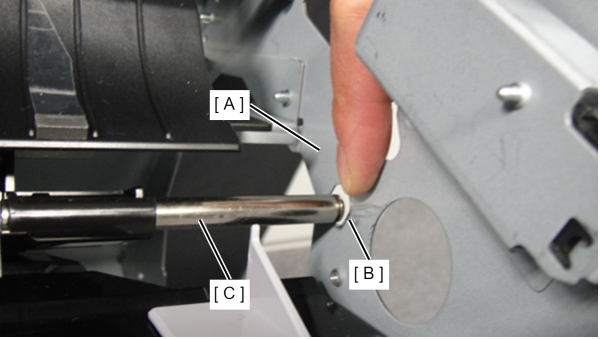
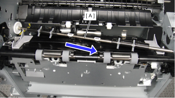
Remove the paddle shaft assembly (A) in the direction of the arrow.
 Assembly / 組み立て
- When assembling, check that the paper holding plate (A) of the paddle shaft assembly is inserted into the frame (C) of the paper guide (B).
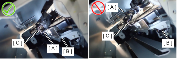
- Set the dowel of the paper guide (A) to the bearing of the paddle shaft assembly (B).
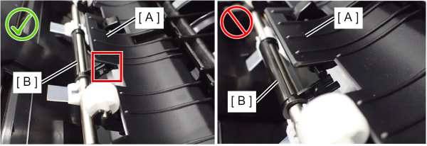
- When assembling, check that the paper holding plate (A) of the paddle shaft assembly is inserted into the frame (C) of the paper guide (B).
Remove the clamp (A) from the metal plate.
- Remove the cable retainers (x2) (A) to release the cable (C).
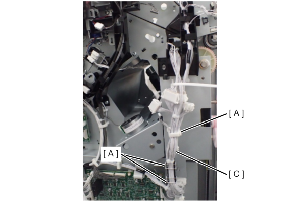
- Extract the cable holder (A).
- Remove 3 screws.
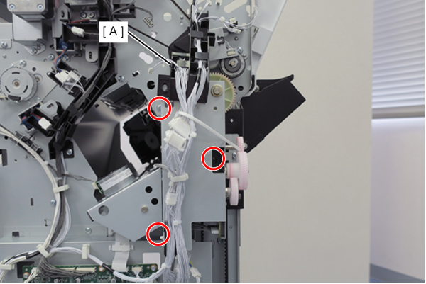
- : 4x8D/P
- Remove the plastic E-ring (A) and bearing (B).
- While supporting the lower tray, remove the tray motor assembly (C) from the metal plate.
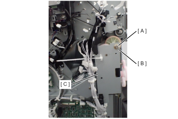
- Remove the cable (B) that secures the cable (B) of the tray motor assembly (A) from the metal plate, and disconnect the cable (B) from the connector (D).
- Remove the tray motor assembly (A).
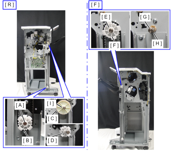
On the back side, remove the plastic E-ring (A) and remove the lower lifting gear (without horizontal pin) (B).
Caution / 注意Be careful not to lose the horizontal pin when removing the gear.
Remove the plastic E-ring (I) and remove the lift relay gear (C).
After removing the lifting relay gear (C), remove the upper lifting gear (D).
Remove the plastic E-ring and bearing.
On the front side, remove the plastic E ring (E) and remove the lifting gear (F).
- Remove the plastic E-ring (G) and the bearing (H).
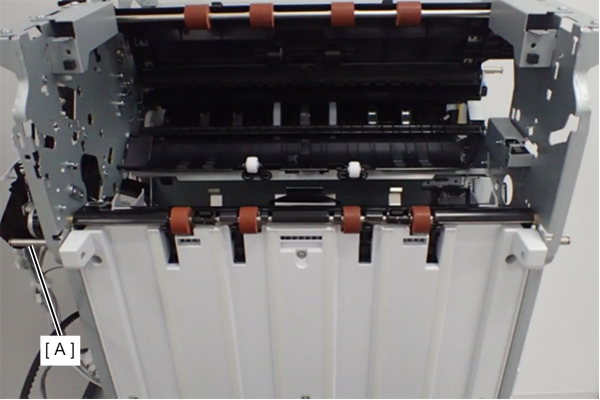
- Remove the lower tray lifting shaft.
- Remove 1 screw and remove the FIN Shift Arm Set Position HP Sensor (A).
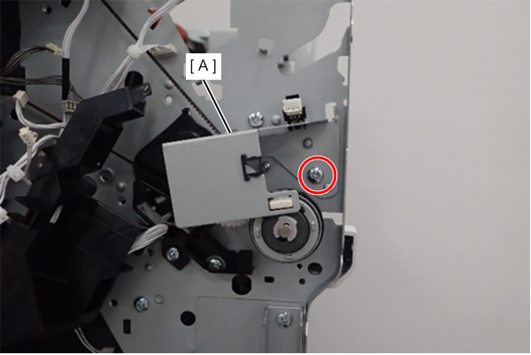
- : 4x8D/P
- Remove the cables (x2) (A) from the connectors.
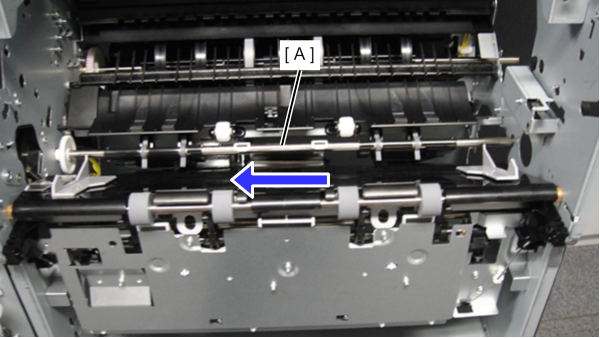
- Remove one screw and take away the harness frame cover (A).
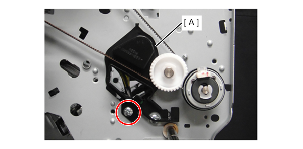
- : 4x8D/P
On the back side, remove the plastic E-ring (A) and remove the paper ejection clutch (B).
Remove the plastic E-ring and bearing (C).
Remove the plastic E-ring and bearing (D) on the front side.
While lifting the lower unit (E) upward, remove the lower paper ejection roller (F) from the shaft hole on the front side.