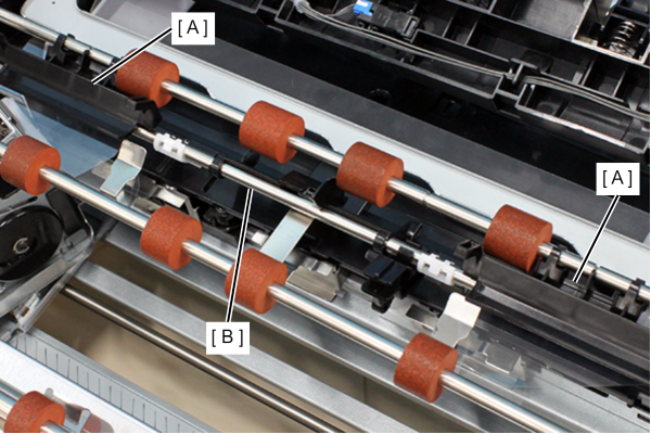
MID Roller
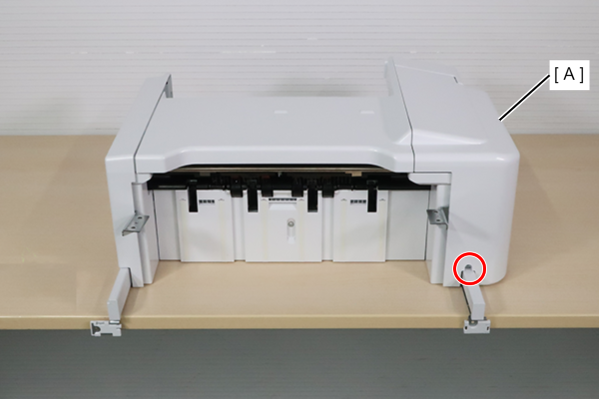
- Refer to the following and remove the inner finisher from the printer.
Inner Finisher Installation Procedure
 Caution / 注意
- When disconnecting the Inner Finisher Unit from the Main Unit, the power of the Main Unit must be turned off.
- Remove the two screws and remove the tray assembly (A).
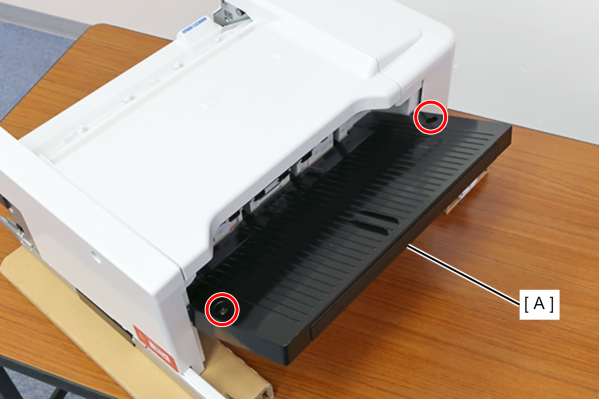
 : 4x8DC/BK/P
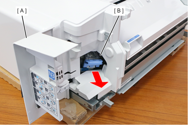
- Open the cartridge cover (A) and remove the Staple Cartridge (B).
- Remove 1 screw of the Housing Front (A).
- : 3x8DC
- Open the cartridge cover (A) and remove the screw securing the Housing Front.
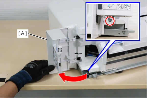
- : 3x8DC
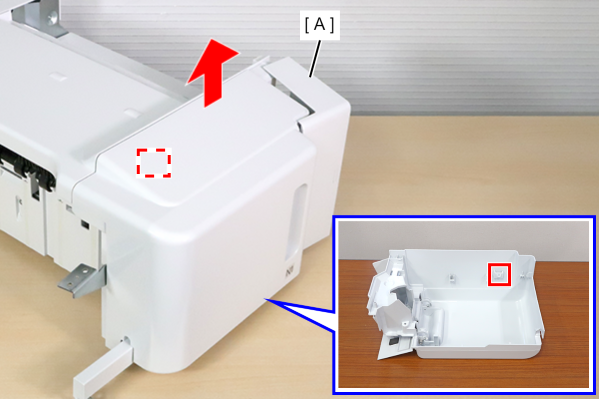
- Lift the Housing Front (A) to unhook.
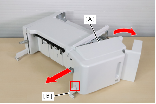
- Open the right side of the Housing Front (A) and slide it to the left to remove the interference with the rail (B) and remove the Housing Front (A).
 Check Point / チェックポイント
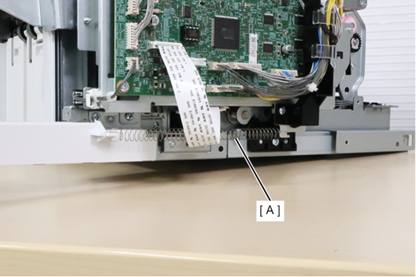
Be careful the Housing Front (A) can easily get caught by extension spring on the inside.
 Assembly / 組み立て
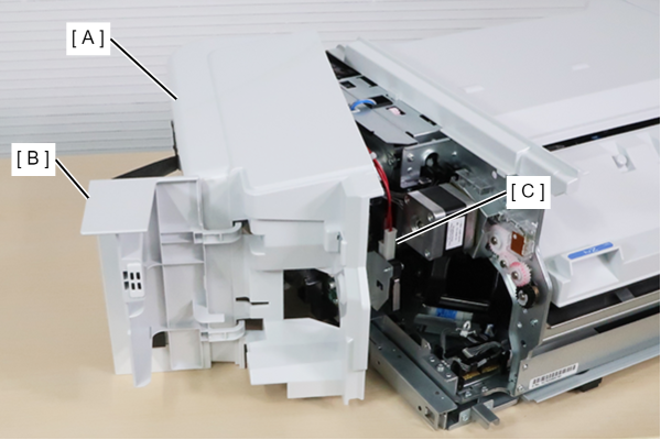
Install the Housing Front (A) with the cartridge cover (B) opening. The protrusion inside the cartridge cover (B) may contact the cover open sensor (C) and damage it.
- Remove the 3 holders from the cable guide (A) by using flathead (-) screwdriver.
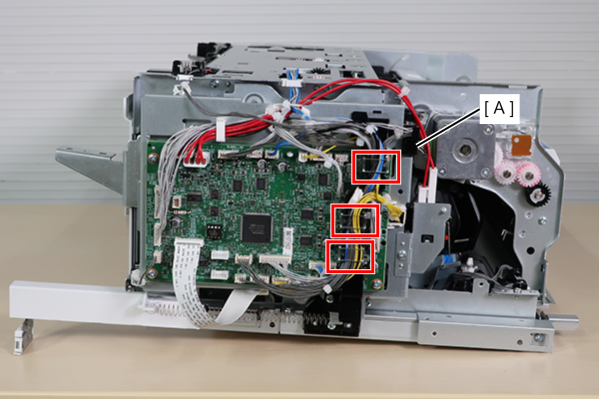
- Disconnect all cables and FFC from Main Board (A).
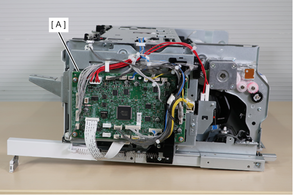
- Release all cables from the cable guide (A).
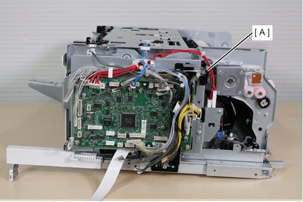
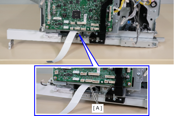
- Release the FFC clamp (A).
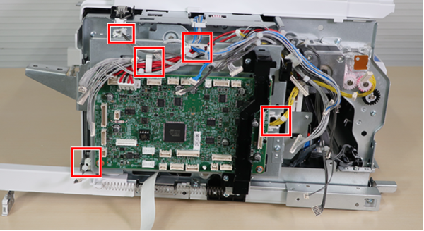
- Release the cable from 5 clamps.
- Remove 1screw, rotate the cover open sensor (A) toward the product to remove the dowel, and lift it upwards to remove it.
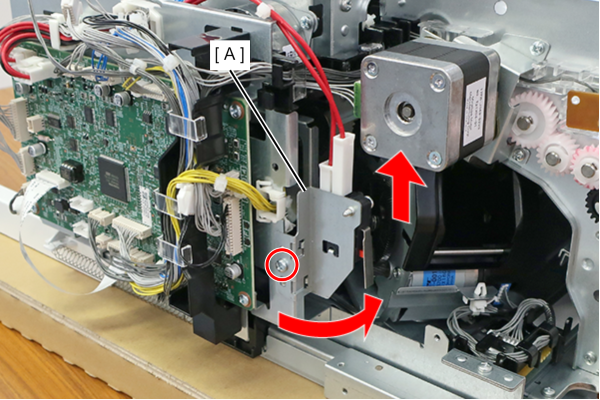
- : 3x8D
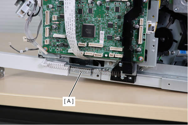
- Remove the extension spring (A).
- Remove the 3 screws fixing the Main Board Assy (A).
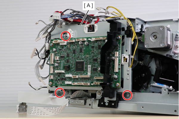
- : 3x8D
- Unhook the cable guide (B) from the hole in the Main Board Assy (A) and remove the Main Board Assy (A).
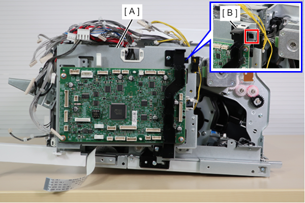
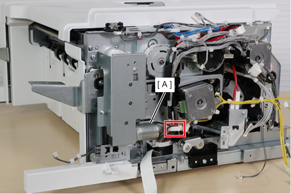
- Release the lift motor (A) cable from the clamp.
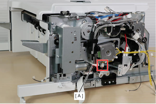
- Remove the cable (A) from the relay connector.
- Remove 3 screws and remove the Lift Motor Assy (A).
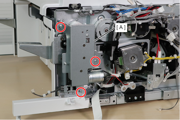
- : 3x8D
Caution / 注意If the Lift Motor Assy (A) is removed, the tray sheet metal (B) may come loose and fall.
When removing the Lift Motor Assy (A), support the tray sheet metal (B) and be careful not to drop it.
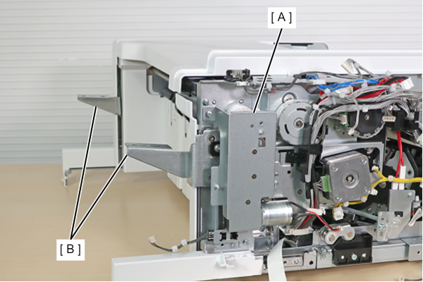
- Remove the cable (B) from the Stapler Carriage HP Sensor (A) connector.
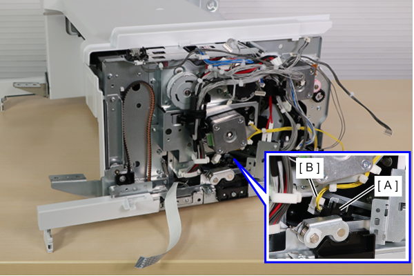
- Lift the left cable guide (A) upward while releasing the dowel by pushing it from the back side of the frame, and remove the left cable guide (A) from the frame.
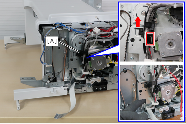
- Mark the cables and connectors (A) that connect to the 2 motors.
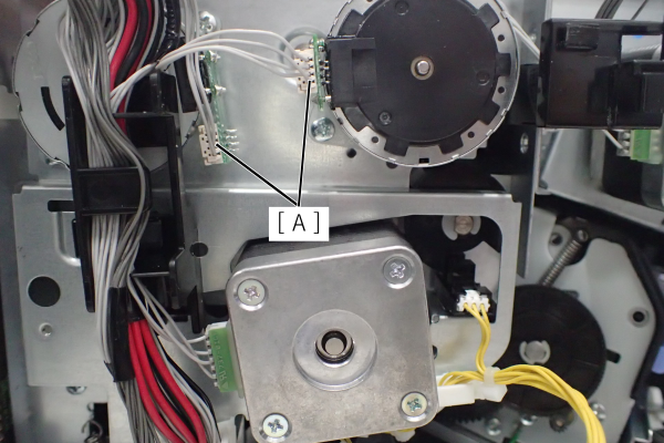
 Note / 補足
Check cable and connector markings during assembly as cables may be mis-inserted.
- Disconnect the cables (A) connecting the three motors and release them from the left cable guide (B).
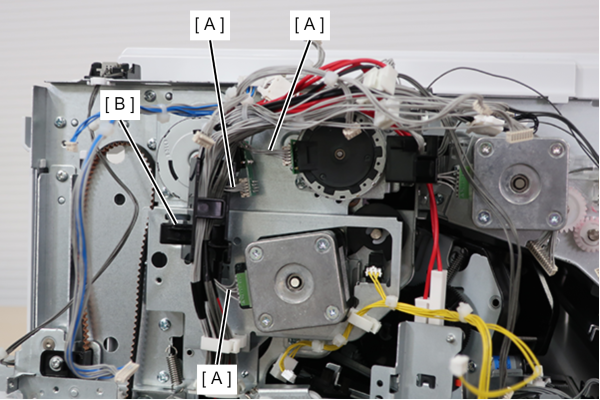
- Release the cable from 2 clamps.
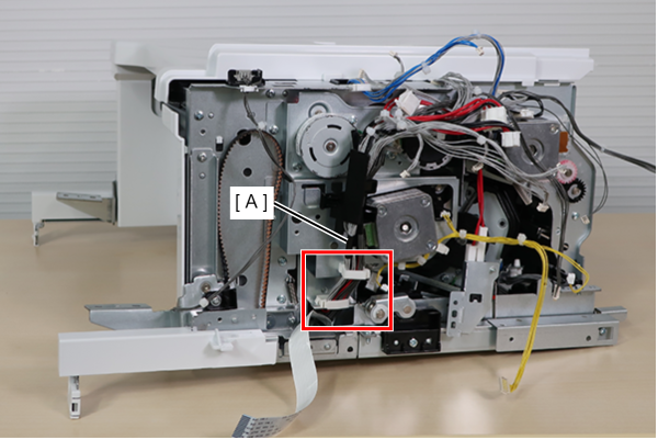
- Remove the two holders from the right cable guide (A) using a flat-tipped tool such as a flathead screwdriver to release all cables routed to the right cable guide (A).
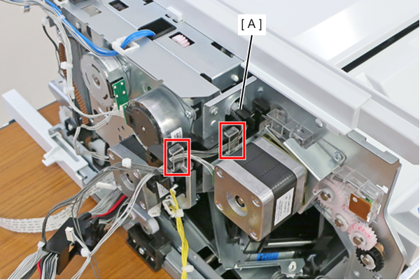
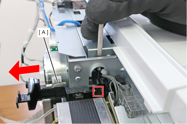
- Remove the right cable guide (A) by releasing the dowel from the back side using flathead screwdriver.
- Remove 4 screws and remove the Motor Assy (A).
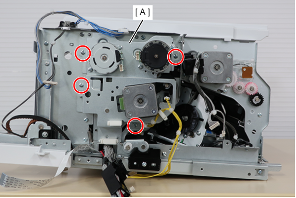
- : 3x8D
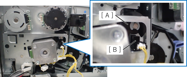
Assembly / 組み立てAvoid Cam (A) and IN FIN Alignment Paddle HP Sensor (B) from colliding.
- Remove 2 screws of the Housing Rear (A).
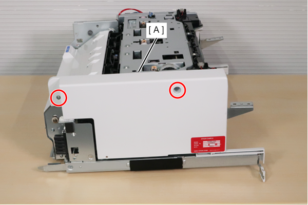
- : 3x8DC
- Open the upper side of the Housing Rear (A) and lift it diagonally upward to remove it.
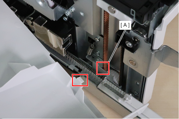
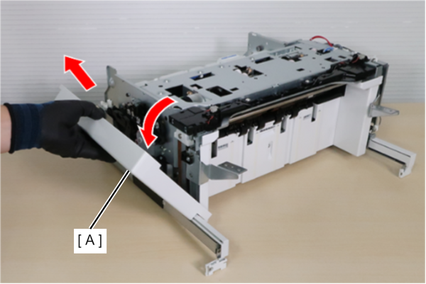 Assembly / 組み立て
Install the Housing Rear by hooking the inner hook to the frame (A).
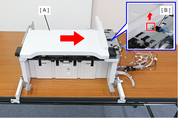
- Slightly lift the front side of the upper housing (A) to remove the hook, and slide the upper housing (A) to the front until the hook hits the cable guide (B).
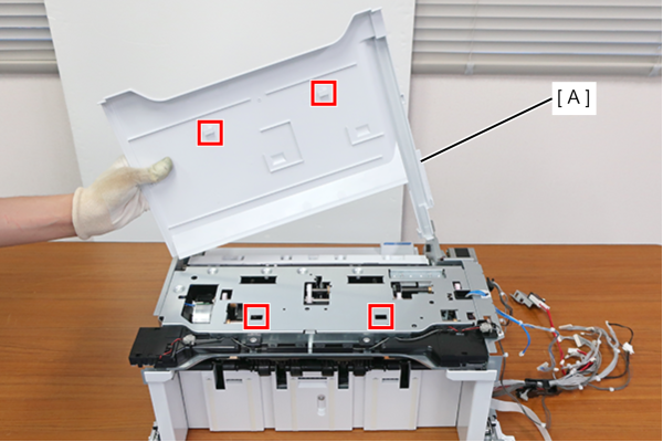
Remove the top of the housing (A) by lifting it diagonally.
Assembly / 組み立てAttach the two hooks on the housing upper (A) through the holes.
- Release the cable (B) of the Upper Unit (A) from the clamp.
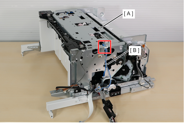
- Remove 2 screws of the Upper Unit (A).
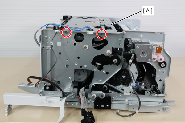
- : 3x8D
- Remove 1 screw of the Upper Unit (A).
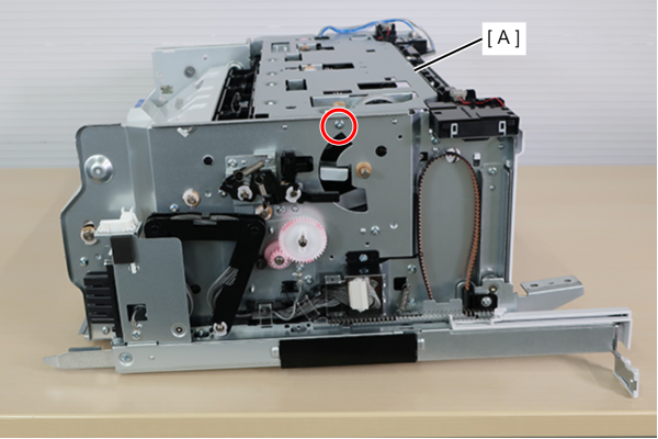
- : 3x8D
- While spreading the front and rear frames outward, remove the four dowels on the Upper Unit (A).
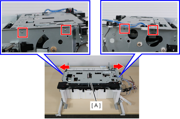 Assembly / 組み立て
Insert dowels one by one while widening the frame using a flathead screwdriver.
Be careful not to get your hands caught.
- Pull out the Upper Unit (A) from the tab and remove it.
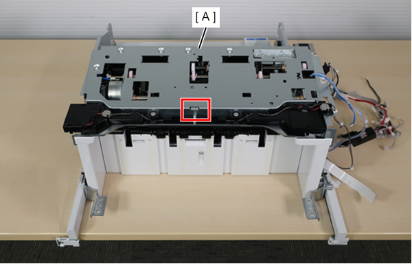
- Move the sector gear (A) in the direction of the arrow to remove the flag (B) from the sensor section (C).
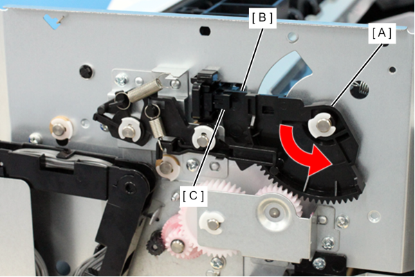
- Push the hook (A) in the direction of the arrow to release it, and remove the IN FIN Rear-Edge Tapping HP Sensor Assy (B).
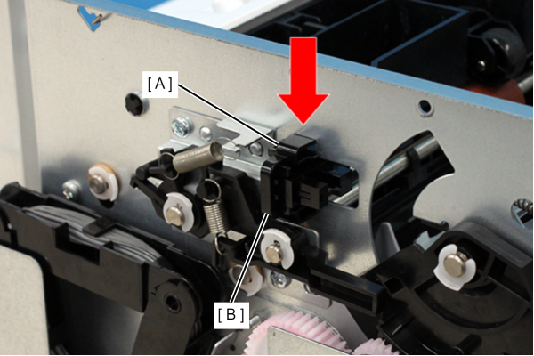
- Remove the cable from the connector (A) and remove the IN FIN Rear-Edge Tapping HP Sensor Assy (B).
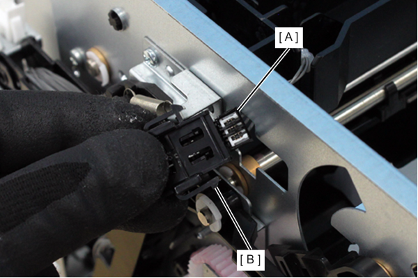
- Remove 2 screws and remove the holder (A).
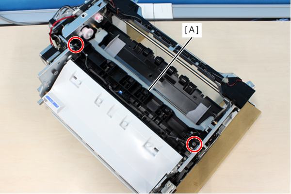
- : 3x8DC
- Remove the spring (A) of the torsion spring from the hole in the frame.
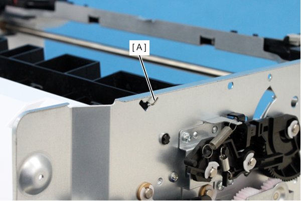
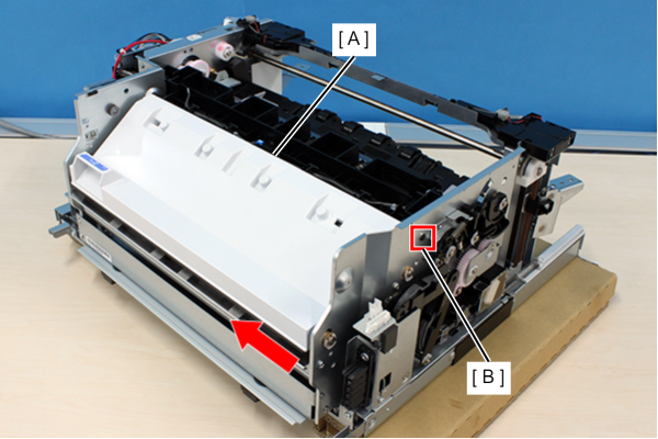
- Push the Upper Paper Feed Assy (A) in the direction of the arrow to remove the dowel (B) and remove the Upper Paper Feed Assy.
- Remove 3 screws and remove the Paper Transport Motor Assy (A).
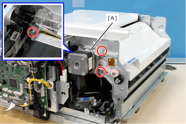
- : 3x8D
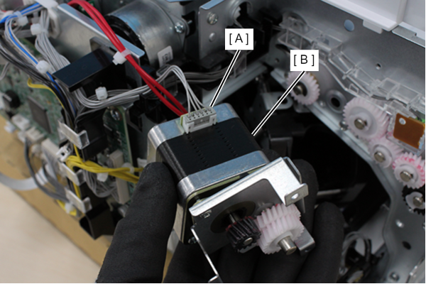
- Disconnect the cable from the connector (A) and remove the Paper Transport Motor Assy (B).
- Remove the 4 screws of secure the Paper Feed Roller Cover (A).
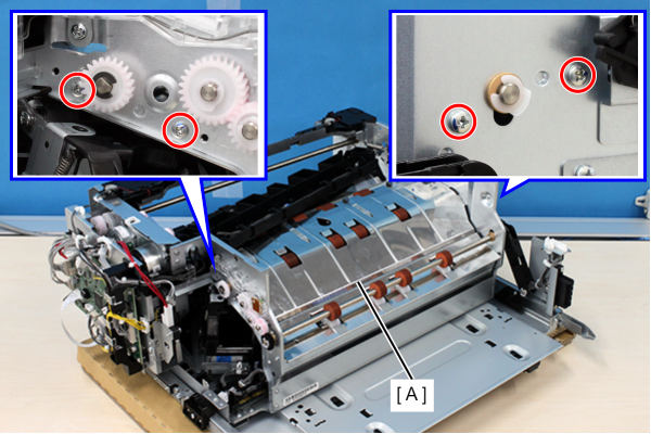
- : 3x6D
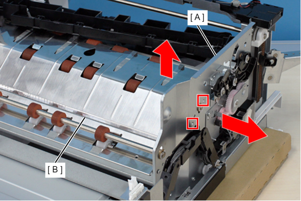
- Spread the rear frame (A) in the direction of the arrow and release the 2 dowels while lifting the rear side of the Paper Feed Roller Cover (B).
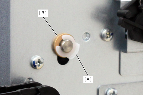
 Check Point / チェックポイント
If the frame is too stiff to release the dowels, removing the E-ring (A) and bushing (B) will make the work easier.
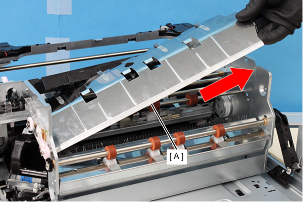
- Remove the Paper Feed Roller Cover (A) in the direction of the arrow.
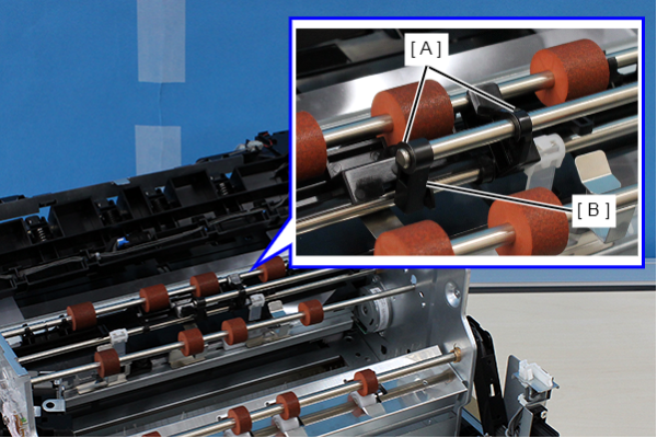
- Remove 2 C-rings (A) and remove the connecting arm (B).
 Assembly / 組み立て
Attach the connecting arm (A) by engaging it with the dowel of the Paper Holder (B).
- Remove 2 screws and remove the Rear-Edge Tapping Mechanism Assy (A).
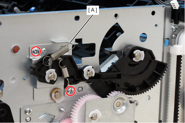
- : 3x8D
Assembly / 組み立てAttach the Rear-Edge Tapping Mechanism Assy (A) by passing the shaft through the hole in the connecting part (B).
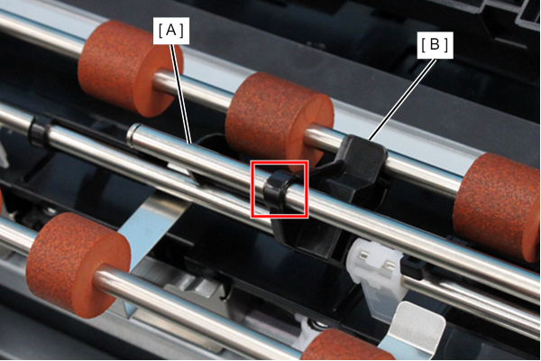
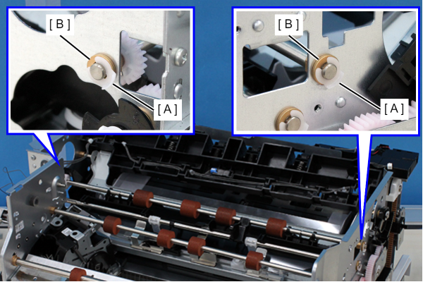
- Remove the E-ring (A) and bush (B) on both ends.
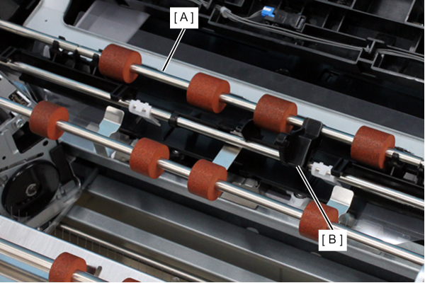
- Remove the connecting part (B) from the intermediate roller (A) and remove the intermediate roller.
 Assembly / 組み立て
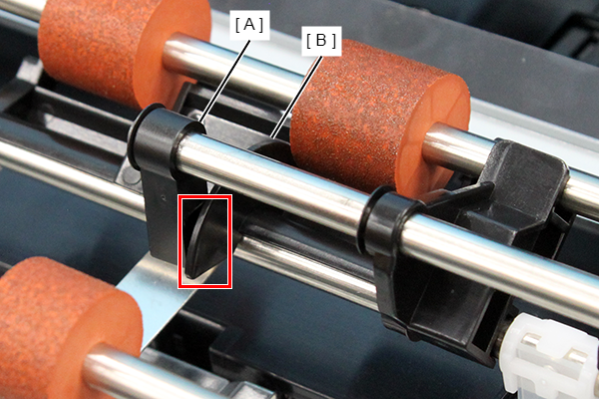
Attach the paper stopper (A) under the paddle shaft (B).
OK
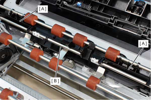
NG