Protecting the products to avoid damages while transporting

Ink cartridge
Protection Point Description

Prevention of ink transfer during transportation

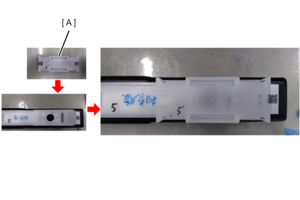
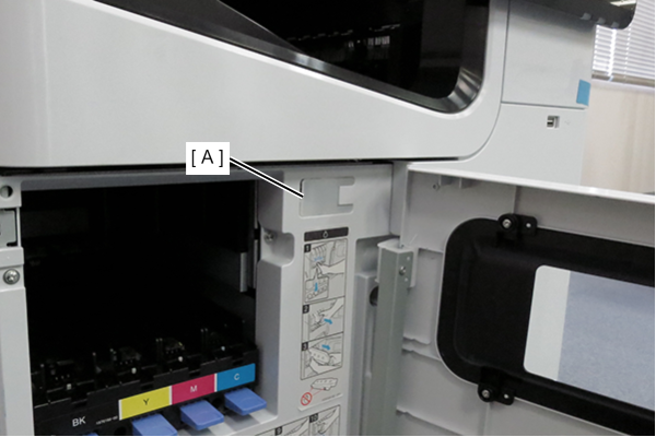
  1. Immediately attach the ink supply port cap (A) to the removed ink cartridge.
    At this time, be careful not to apply vibration or impact before attaching the ink supply port cap.
    If the ink supply port cap is not attached, ink remaining in the supply port may drip.
    *Ink supply port cap is established as ASP.
    If the ink supply port cap is stained with ink, wipe it off with BEMCOT or the like each time.
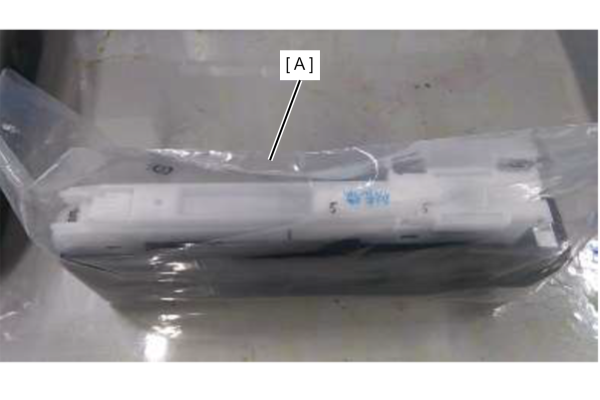
  2. In consideration of the ink supply port cap coming off during transportation, we recommend the following.
    ・Put it in the individual bag (B) in which the ink cartridge was enclosed.
    ・Carry the ink cartrdige so that the ink supply port faces upward.


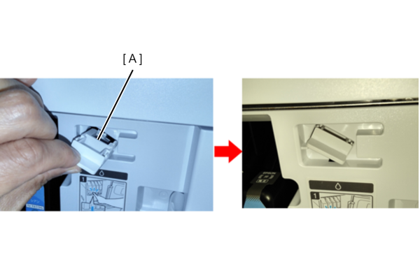
How to attach the ink supply port cap

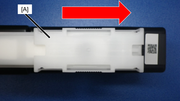
Slide the ink supply port cap (A) in the direction of the arrow until it clicks.

The shape of the ink supply port cap is bilaterally symmetrical, so it can be installed in either direction.


Main Unit
In Right Door Cover
Caution / 注意

To prevent contact with the Belt surface during work, be sure to perform the items listed in the table in order from the top.

Protection Point Description

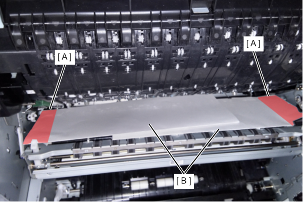
Prevents rubbing of belt and belt gap regulating surface (A) due to vibration during transportation

  1. Open the Belt Unit.
  2. Fold two sheets of A4 paper (B) vertically in half and place them on the belt surface and gap regulation surface.

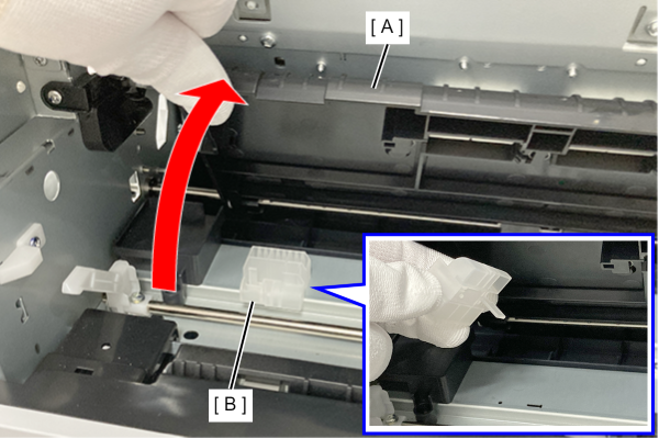
Prevents the lift gear from coming off the cap unit due to vibration during transportation

  1. Open the conveying path (A) upward and take out the cap conveying member (B).
    * If the transportation parts are not stored in the position shown in the left figure, please purchase ASP.
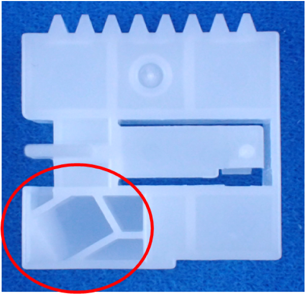
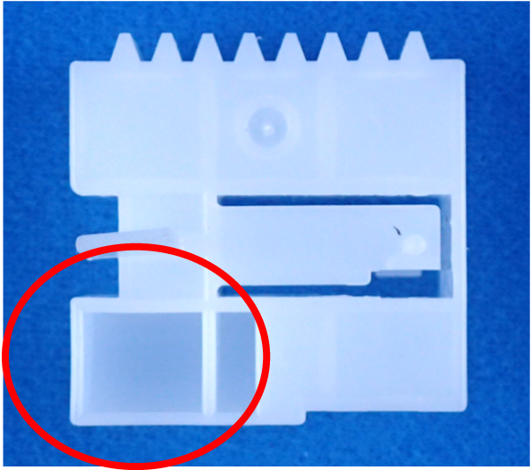
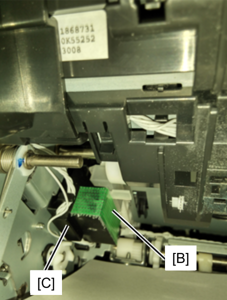
  2. There are two types of transport caps, old type and new type, with different shapes.
    Refer to the images below to determine which type of transport cap you have removed.
    • New type
    • Old type
    The procedure differs depending on whether the cap is a new or old type as described below.

    • How to install the new type of transport cap
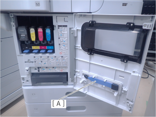
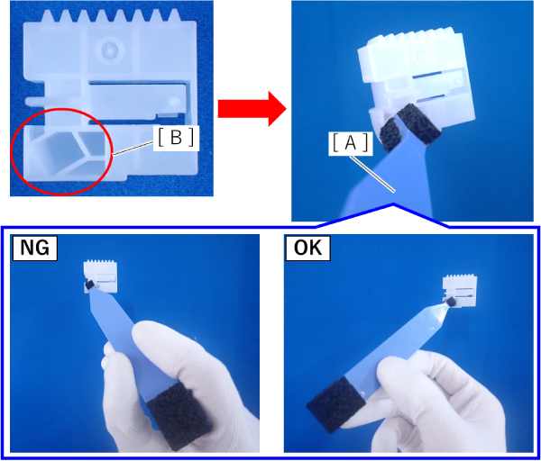
      1. Open the front cover, and remove the cleaner stick (A).
      2. Insert the tip of the cleaner stick (A) into the hole (B) in the transport cap.
        Be careful not to insert the cleaner stick in the wrong orientation.
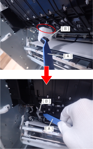
      3. Hold the cleaner stick (A) and insert the transport cap (B) in place.

    • How to install the old type of transport cap
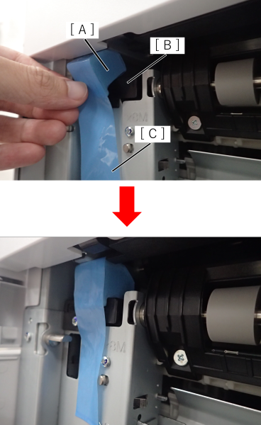
      1. Open the Belt Unit.
      2. Insert the transport cap (B) in place and secure it with tape (C).

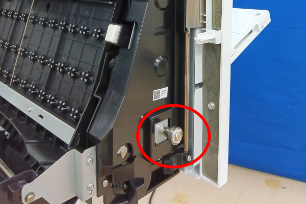
Prevention of right door bearing axis bending

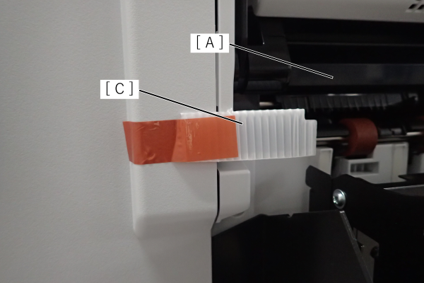
  1. Insert the right door transportation part (A) between the cover (B) and the right door, and secure it with tape (C).
    *Transportation part are cushioning materials included in new products. If lost, purchase ASP.
In Front Cover
Protection Point Description

Prevention of Head unit lifting gear disengagement

  1. Take out the Head transportation part (A) stored in the upper the Front cover.
    * If the transportation parts are not stored in the position shown in the left figure, please purchase ASP.
  2. Insert the head transportation part (A) into the specified position.

Front
Protection Point Description

Prevent the front cover from opening

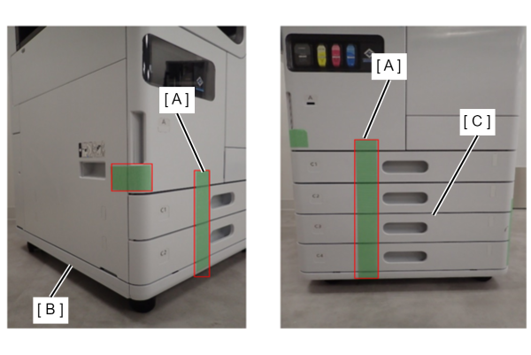
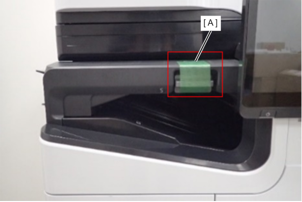
  1. Apply tape (A) under the handle of the Front Cover to secure the cover.

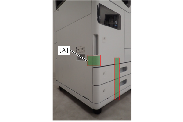
Cassette tray pop-out prevention

  1. Fix the area from the Front cover to the bottom of the main unit with tape (A).
    When installing the Caster table (B), do so up to the bottom of the caster base.
    When installing an additional cassette unit (C), fix all four cassettes.
Right side
Protection Point Description

D1 cover/B cover/E cover opening prevention

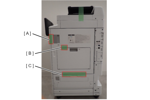
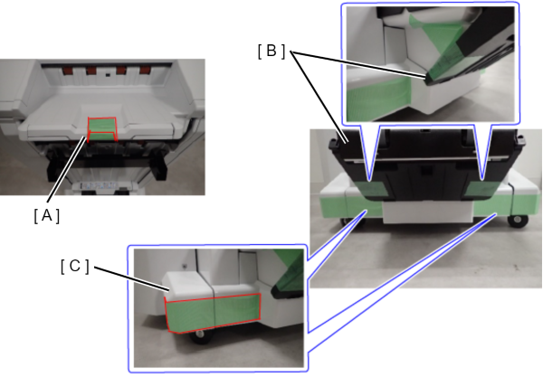
  1. Fix the front of the D1 cover handle with tape (A).
  2. Fix the upper of the B cover and the D1 cover with tape (B).
  3. Fix the E cover and the D1 cover with tape (C).
ADF/SCN
Protection Point Description

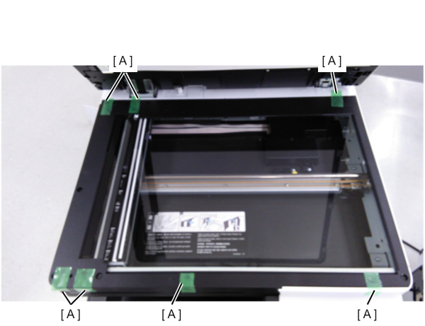
Preventing rubbing at the contact point between the flatbed of the SCN unit and the ADF unit

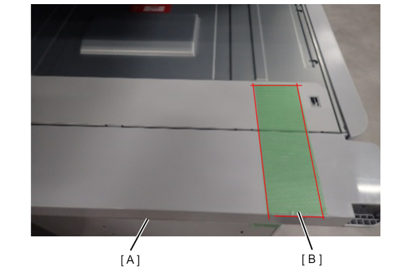
  1. Fix the protective tape (A) to the seven contact points on the flatbed of the SCN unit with the ADF unit.

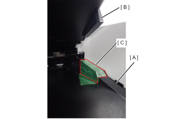
Prevents contact surface abrasion between the ADF tray and ADF output tray

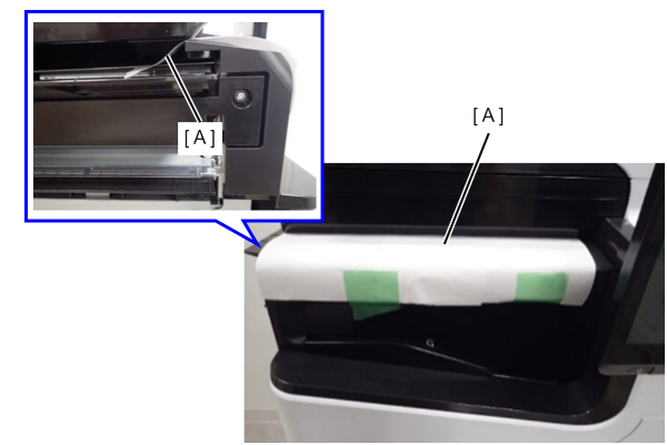
  1. Fix the protective tape (C) where the ADF output tray (A) contacts the ADF document tray (B).

Preventing the ADF document tray from flapping

  1. Secure the tip of the ADF tray and the main unit of the ADF unit with tape.
No eject option parts installed
Protection Point Description

ADF/SCN Unit fall prevention

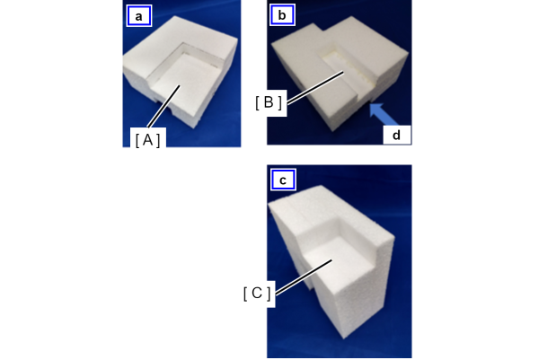
<Shape of ADF/SCN support part>
a: Surface
(A) ADF/SCN support surface without option
b: Back side
(B) Relief groove for the protrusion at the end of the output tray of the main unit
c: d direction view
(C) Support surface of ADF/SCN with inner bridge attached

----

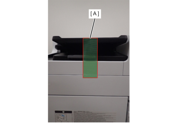
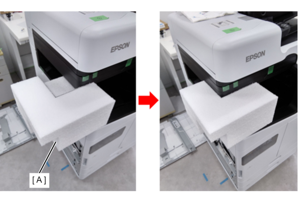
  1. Insert the cushioning material included in the new product between the ADF/SCN unit and the main output tray.
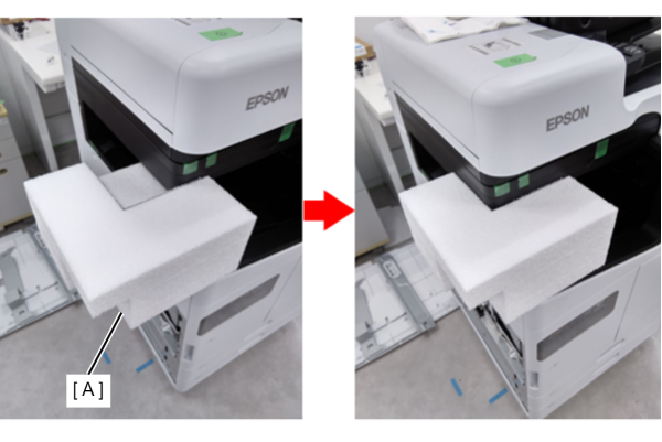
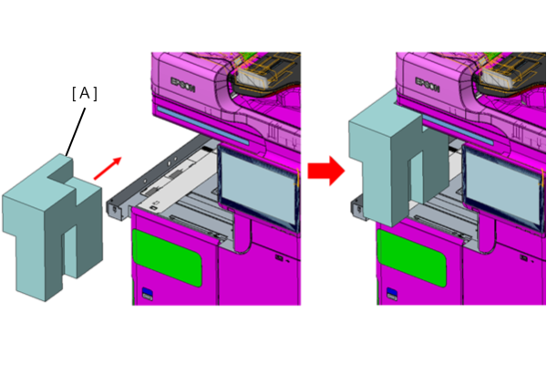
  2. If the above cushioning material is not available, push in the ADF/SCN support part (A).
    * ADF/SCN support parts are enacted in ASP.
    * Align the groove (B) on the back of the ADF/SCN support part with the triangular protrusion on the edge of the output tray, and insert it from the left side of the main unit.


Floor finisher
Protection Point Description

Prevention of deformation of Bundle Eject Unit

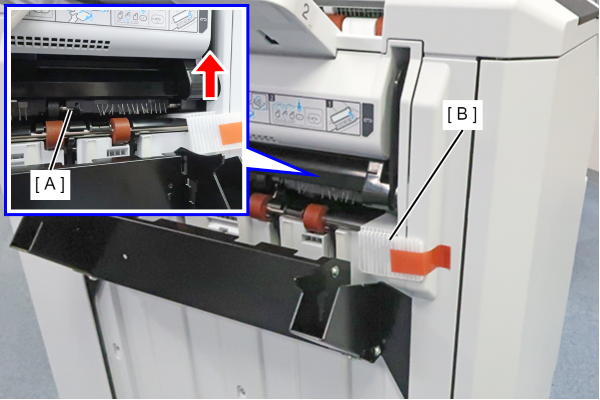
  1. Lift the ejection part (A), attach the protective material (B) that was stored, and secure it with tape.
  2. Attach the protective material (C) that was stored in the ejection part (A) and secure it with tape.

Prevention of breakage of protruding parts

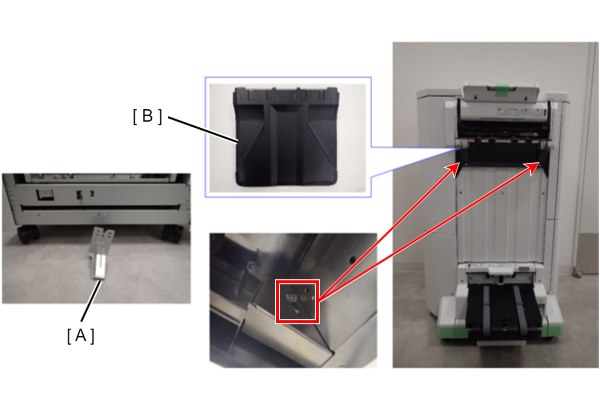
  1. Earth plate (A): Remove and send separately.
  2. Main tray (B): Release the hooks on both sides of the tray, remove the tray, and send separately.

Preventing moving parts from coming off and popping out

  1. Upper tray (A): Secure the tip of the tray with tape so that the extension tray does not pop out.
  2. Saddle unit movable tray (B): Secure both sides with tape to prevent it from swinging.
  3. Lower cover (C): Secure both sides with tape to prevent it from coming off.

Preventing opening and closing of the paper path of floor bridge unit A

  1. Fix Jam release lever with tape (A).

Preventing rubbing between floor bridge unit A and the bottom of the SCN unit

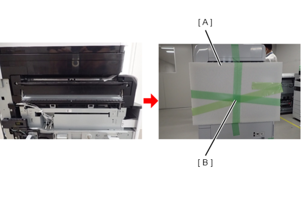
  1. Insert A4 paper (A) between floor bridge unit A and SCN unit.

Prevention of deformation of floor bridge unit A, polyester film and finisher connection mechanism

  1. Secure cover part (A) with tape (B).
    The cover part (A) is enacted in ASP.
Inner Finisher
Protection Point Description

Preventing the Paper eject tray from falling off

  1. Remove the Paper eject tray and send it separately.

Preventing the fixing plate the Paper eject tray from rattling

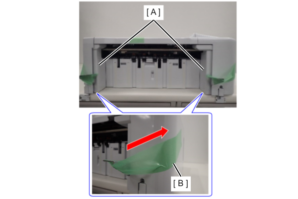
  1. Pull up the Paper eject tray fixing plate (A) on both sides and fix it with the tape (B).

Preventing the Inner finisher from sliding

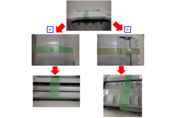
  1. Secure the front, top, rear plate, and bottom plate with tape.
    a: Without punch unit
    b: With punch unit

Preventing damage to the main unit and inner finisher


Without punch unit:

  1. Place the cured unit in the removal packing material (A) and return it to the original packing box.

With punch unit:

  1. Leave the cushioning material on the bottom of the original packing box, and remove the cushioning material on the front and back of the unit.
  2. Put the cured unit in the removal packing material and place it in the box.
  3. Avoid the protrusion (B) on the side of the unit and fill the gap on the top with an air cushion.

Inner bridge exterior cover prevention

  1. Secure the Inner bridge exterior case (A) with tape (B).

ADF/SCN Unit fall prevention

  1. Push the ADF/SCN support part (A) between the ADF/SCN unit and the bridge unit from the front of the main unit. Note the orientation of the support part.
High Capacity Unit
Protection Point Description

Cable damage prevention

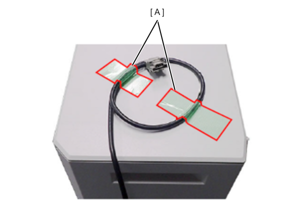
Fix the cable with tape (A).

Inner Tray
Protection Point Description

ADF/SCN Unit fall prevention

  1. Remove the output tray of the inner tray unit, and push the ADF/SCN support part (A) between the ADF/SCN unit and the main eject tray.