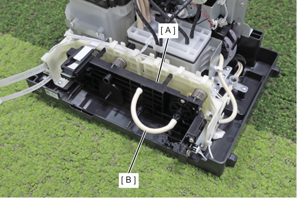
Maintenance Unit
- Remove the 2 screws and remove the Left Cover Upper (A).
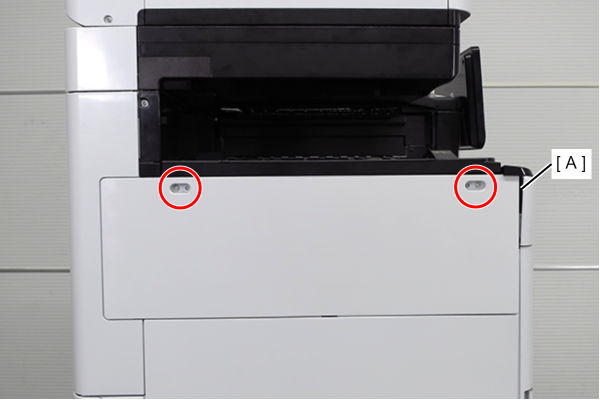
 : 3x10DW
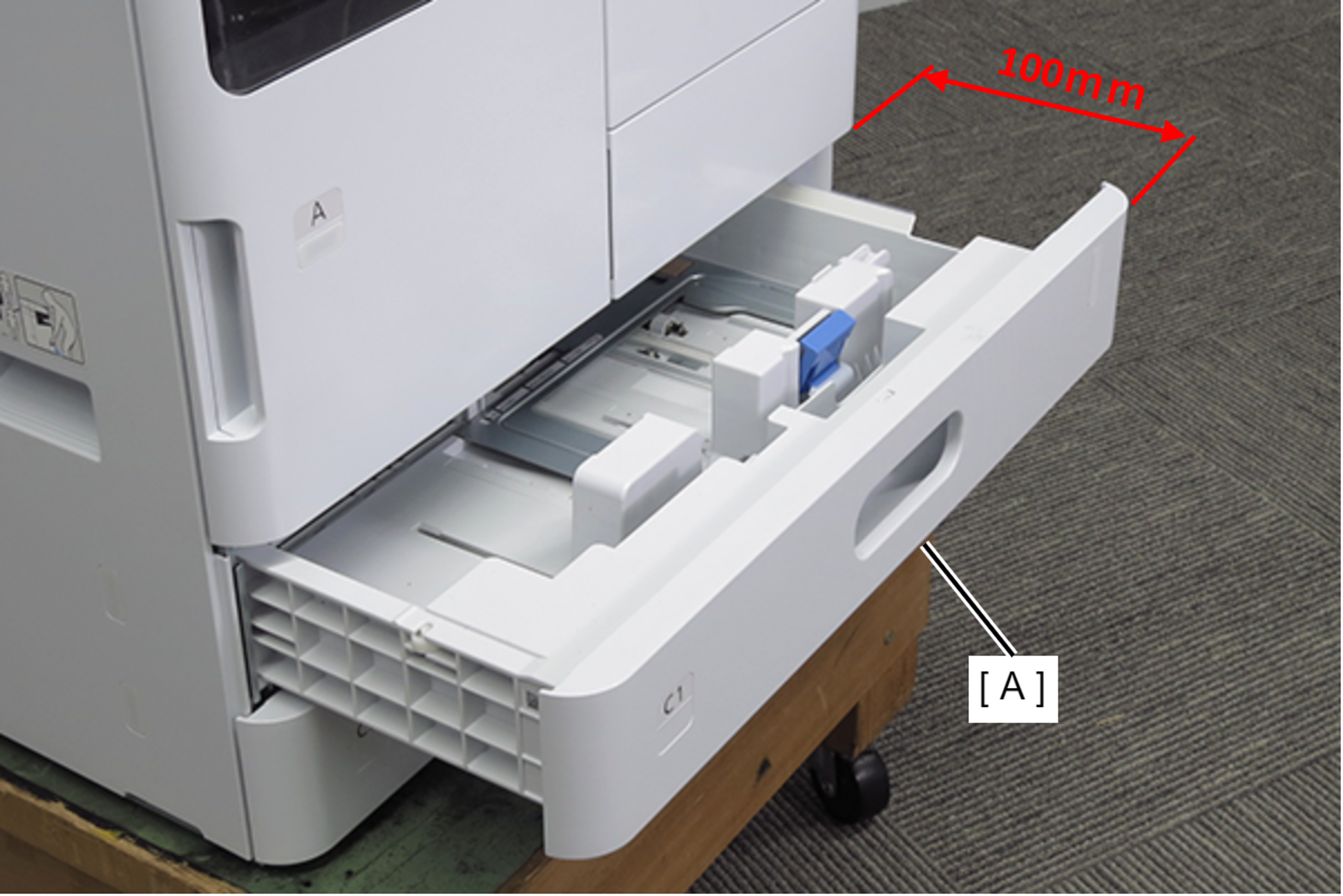
- Pull out the C2 cassette (A). (about 100mm)
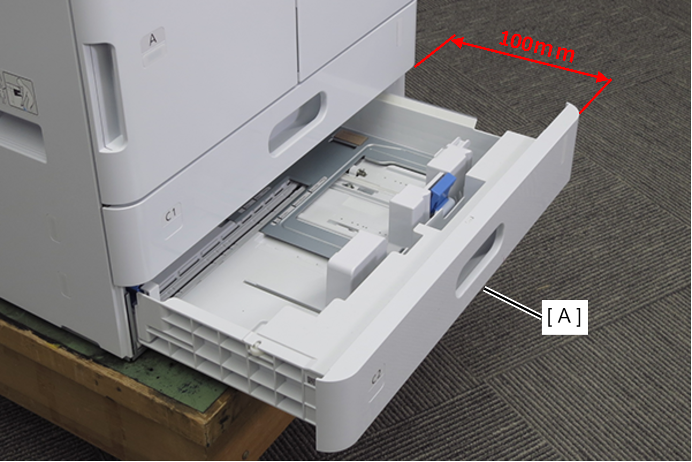
- Pull out the C1 cassette (A). (about 100mm)
- Remove 2 screws and remove the Left Cover Lower (A) in the direction of the arrow.
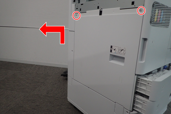
- : 3x10DW
- Remove 1 screw and remove the Left Cover Sub Lower (A) in the direction of the arrow.
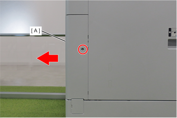
- : 3x10DW
- Remove 4 screws and remove the Handle Frame Assy (A) in the direction of the arrow.
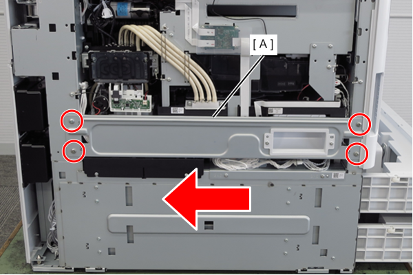
- : 4x8D
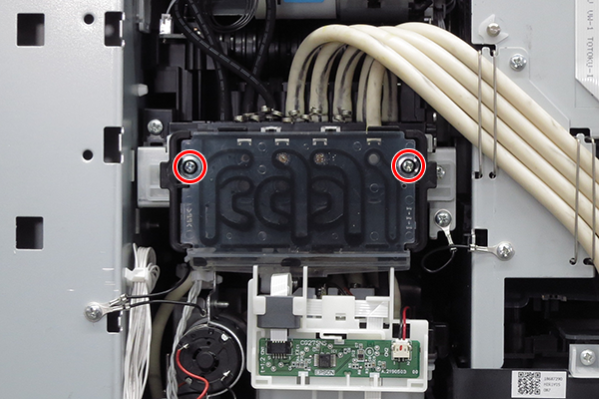
- Loosen the 2 screws.
- Remove the Maintenance Unit, Joint (A).
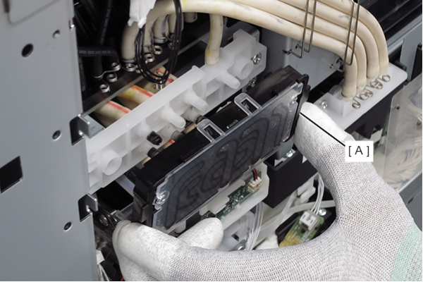
 Assembly / 組み立て
If there is ink on the product during assembly, wipe it off with cloth etc.
- Remove the two cables (A) from the two relay connectors and release them from the two clamps.
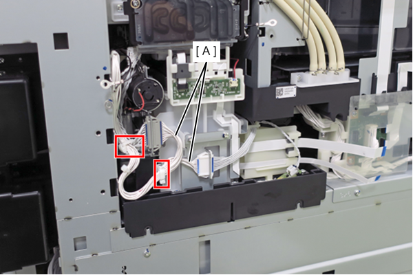
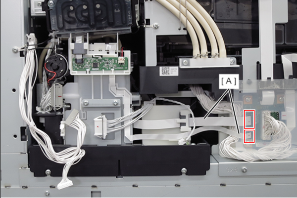
- Remove the 2 FFC (A) from connectors.
- Remove 3 screws.
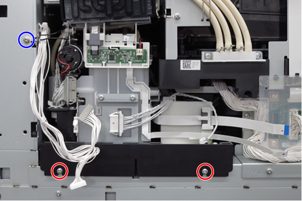
- : 3x8D
 : 3x8D
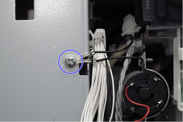
Assembly / 組み立てTighten the screw circled in blue together with the two ground wires.
- Pull out the maintenance unit (A) toward you to remove it.
 Assembly / 組み立て
- Before replacement, be sure to remove the two ink tubes (B) and (C) attached to the maintenance box connection (A) of the maintenance unit ASP.
Installing the maintenance unit without removing the ink tubes may cause parts failure or errors. - Do not discard the ink tube (B) as it will be attached to the maintenance unit that you removed in a later step.
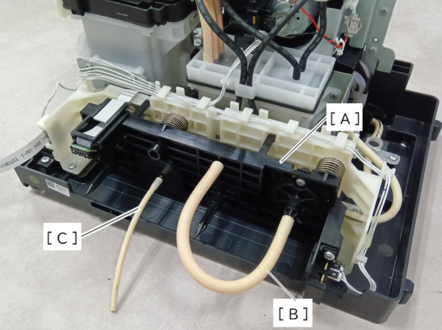
- Before replacement, be sure to remove the two ink tubes (B) and (C) attached to the maintenance box connection (A) of the maintenance unit ASP.
- Attach the cap (B) to the maintenance joint (A) of the removed maintenance unit in order to prevent the cleaning solution from leaking.
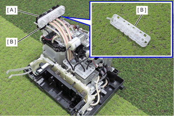
- Attach the ink tube (B) to the maintenance box connection (A) of the removed maintenance unit to prevent leakage of waste liquid.