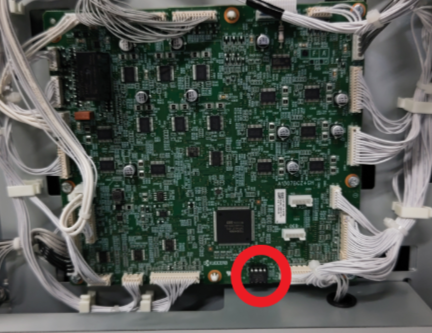
Main Board
 Check Point / チェックポイント Check Point / チェックポイント |
|
- Refer to the following and remove the floor finisher from the printer main unit.
Floor Finisher Installation Procedure
 Caution / 注意
- When disconnecting the Floor Finisher from the Main Unit, the power of the Main Unit must be turned off.
Remove 1 screw of the Rear Cover, Sub (A).
- Put your finger on the recess of the rear cover, sub (A) and open it to the left to remove it.
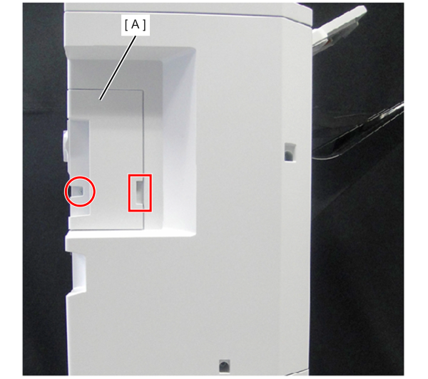
 : 4x10DC
Remove 3 screws of the Rear Cover, Upper (A).
- Slightly raise the top cover (B) and remove the rear cover, upper (A).
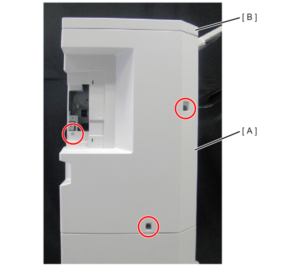
- : 4x10DC
Disconnect all connectors from the Main Board (A).
Caution / 注意When removing the YC22 connector (B), remove the middle stack sensor connector (C) on the side first, then remove the YC22 connector (B). When assembling, make sure the middle stack sensor (C) connector is connected.
 Assembly / 組み立て
- The diagram shows the layout of the connectors of the Main Board.
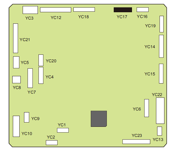
The table shows the layout of the connectors of the Main Board.
Connector No. Pin Color Destination YC1 --- --- Not Used YC2 --- --- Not Used YC3 4 White Discharge cover switch, Front cover switch YC4 7 White Feed Image Board YC5 4 White Feed Image Board YC6 11 White MT Main Board YC7 12 White Punch Main Board YC8 2 White Punch Main Board YC9 5 White Booklet Main board YC10 8 White Booklet Main board YC12 20 White Slider Motor, Discharge Motor, Middle Motor, Carry-in Motor, Ejection Release Motor YC13 4 White Tray Upper Sensor 2 YC14 14 White Shift Release Motor, Shift Motor 1/2, Discharge Clutch YC15 12 White Paddle Motor, Width Alignment Motor YC16 6 White Exhaust Fan YC17 13 Black Stapler YC18 13 White Retraction Drum Motor, Branch Solenoid 1/2/3 YC19 6 White Tray Motor YC20 6 White Drum Sensor, Middle Sensor YC21 19 White Sub Eject Sensor, Sub Tray Full Sensor, Carry-in Sensor, DF Operation Board, Tray Top Sensor 1 YC22 30 White Slide Sensor, Width Alignment Sensor 1/2, Eject Paper Sensor, Stack Ejection Switch, Tray Sensor 1/2, Paddle Sensor, Alignment Sensor, Shift Set Sensor YC23 18 White Shift Sensor 1/2, Tray Sensor 3/4/5, Shift Release Sensor
- The diagram shows the layout of the connectors of the Main Board.
- Remove 6 screws and remove the Main Board (A).
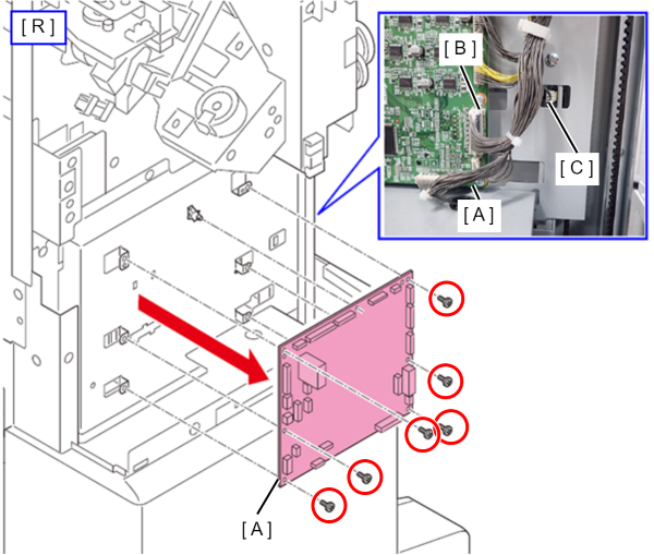
- : 3x8D/P
- Transfer the ROM board to the new main board.
 important / 重要
- Please note that if you forget to transplant the ROM board, the printer will not function properly.