
Main Board
 Check Point / チェックポイント Check Point / チェックポイント |
|
- Remove the 4 screws and remove the right cover sub (A).
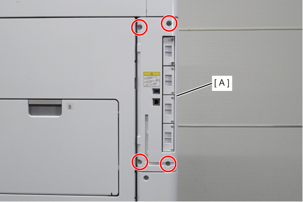
 : 3x10DW
- Remove 1 screw and slide the rear cover (A) in the direction of the arrow to remove it.
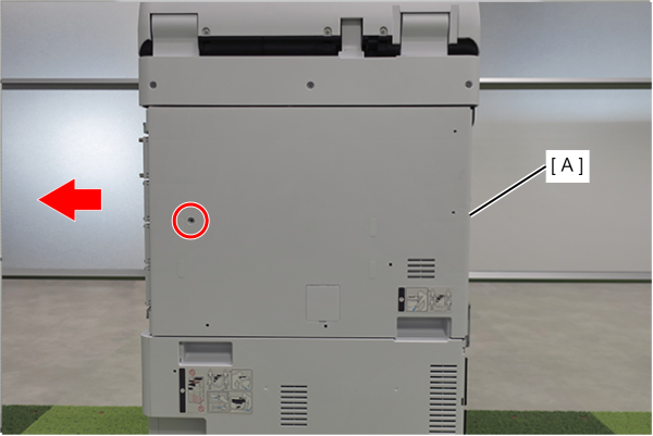
- : 3x10DW
 Assembly / 組み立て
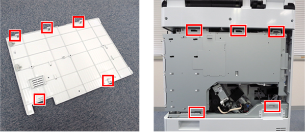
Align the 5 hooks on the rear cover with the 5 holes on the main unit and attach it.
- Remove one screw and remove the shield plate (A) upwards.
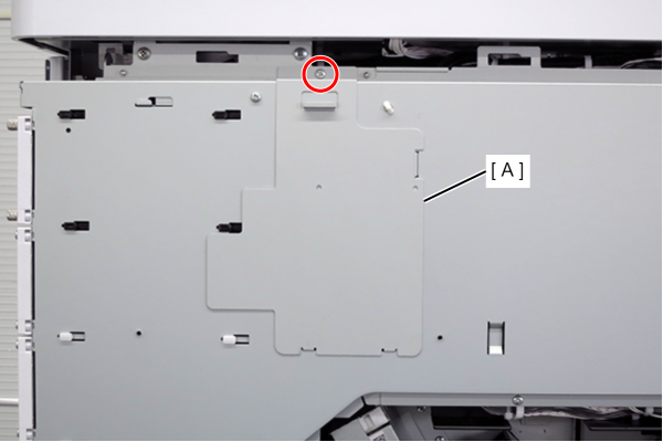
- : 3x8D
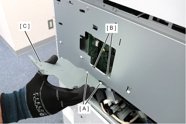
Assembly / 組み立てHook the 2 hooks (A) of the shield plate to the 2 holes (B) of the circuit board box and attach the shield plate (C).
- Disconnect the cable (A) from the connector.
- Remove 3 screws.
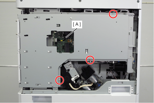
- : 3x8D
 Caution / 注意
When tightening screws, make sure that the screw holes are aligned before tightening.
If the screw holes do not match, the threads may be stripped.
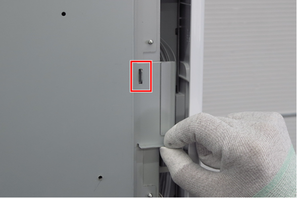
- Lift the handle to release the hook.
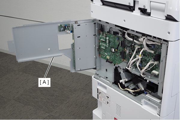
- Open the board box upper case (A).
- Remove the Mech info ROM board (A).
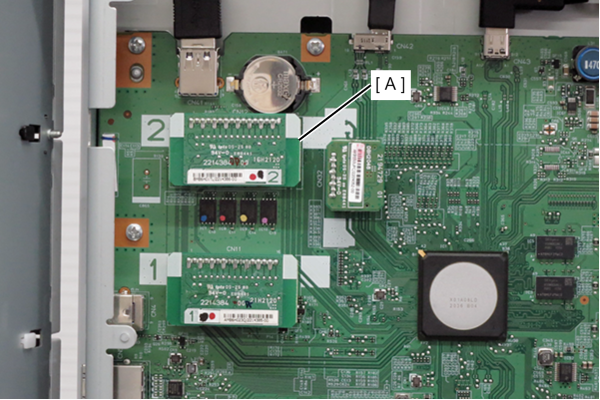
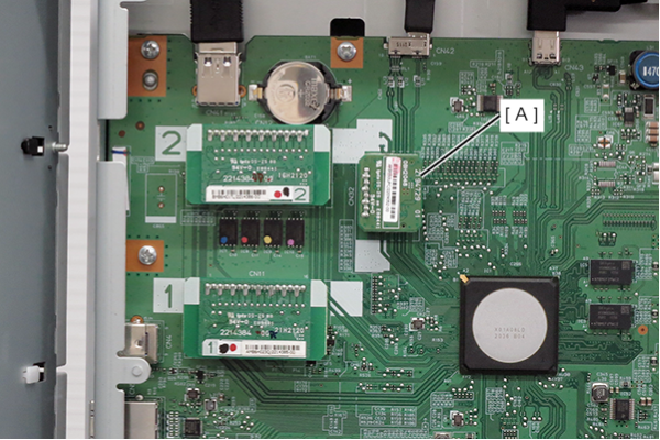
- Remove the TPM Board (A).
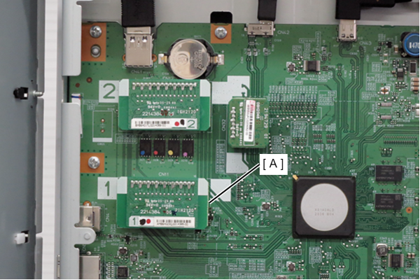
- Remove the User info ROM board (A).
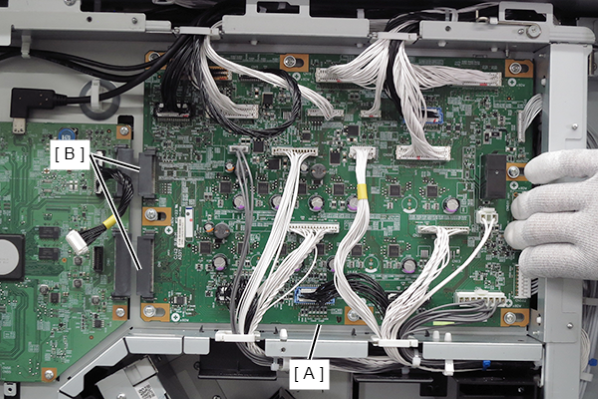
- Loosen the 8 screws of the MCU Board (A).
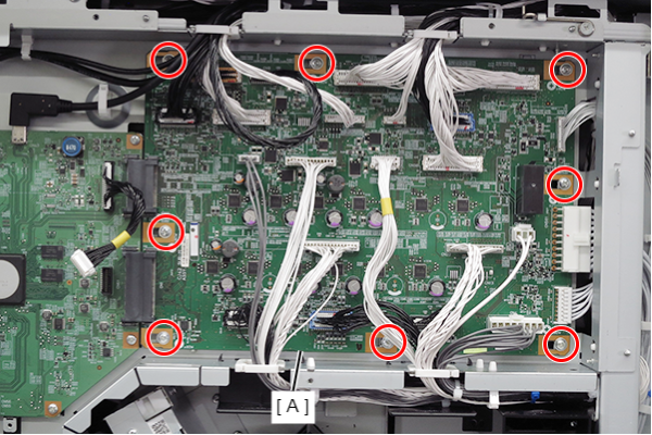
- Slide the MCU Board (A) to the right and disconnect it from the two connectors (B) on the main board.
- Remove 4 screws.
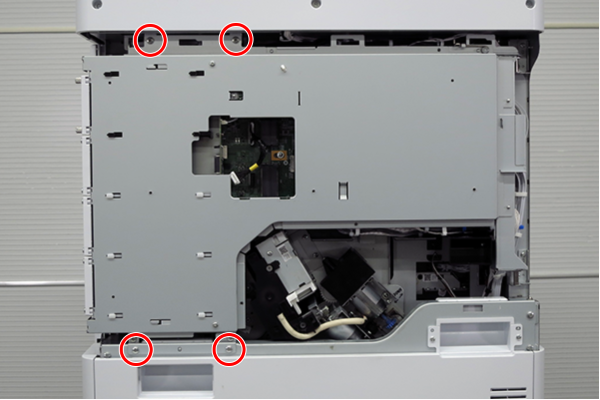
- : 4x8D
- Slightly lift the board box (A) to release the hook.
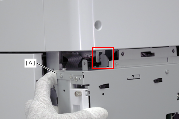
- Open the board box (A).
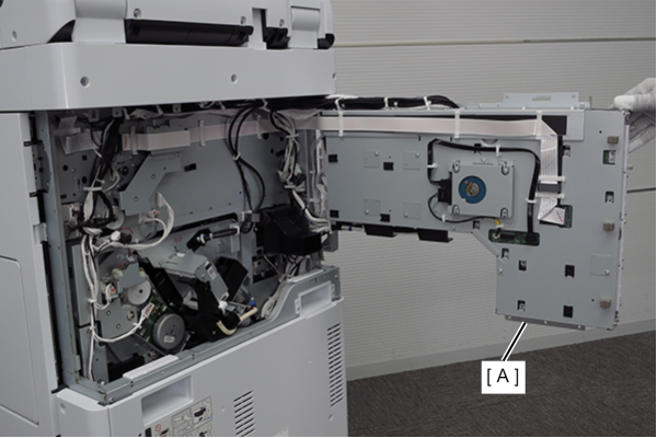 Check Point / チェックポイント
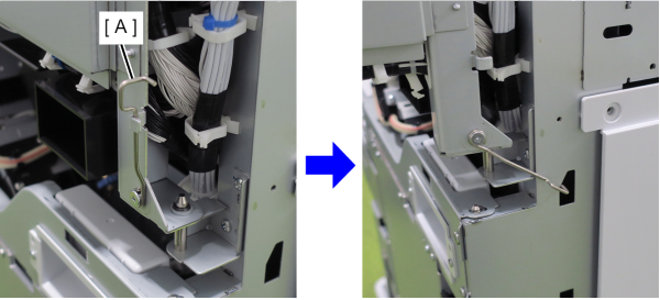
- By hooking the hook (A) of the board box to the hole in the main body, the position of the board box is stabilized, making it easier to work.
- Do not close the circuit board box while hooking the hook (A) on the main unit. The frame may be deformed.
- Remove the cables (A) and FFC (B) from the connectors and release the SATA cable from the clamp (C).
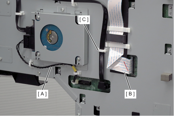
- Remove the SATA cable (A) from the connector.
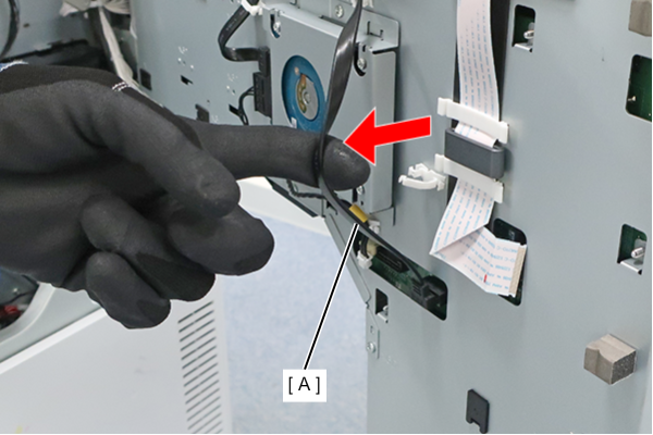 Caution / 注意
Remove the SATA cable by holding the position shown in the figure, as there is a risk of disconnecting the connector on the main board.
- Close the board box and open the board box upper case.
- Remove the four cables (A) from their connectors.
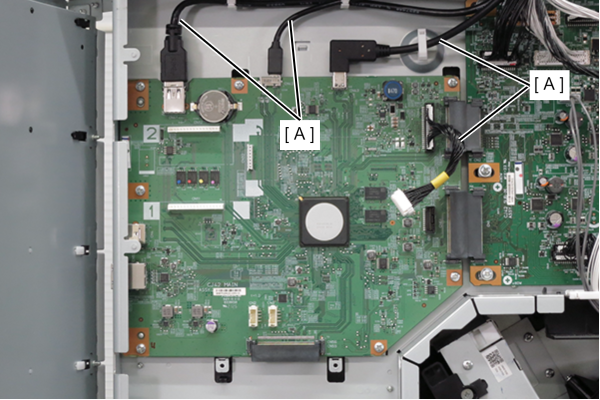
- Remove 7 screws and remove the main board (A).
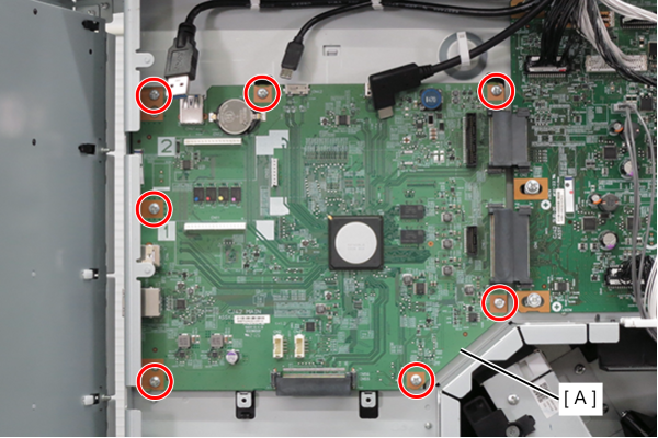
- : 3x8D