
Stapler Rail Unit
- Refer to the following and remove the floor finisher from the printer main unit.
Floor Finisher Installation Procedure
 Caution / 注意
- When disconnecting the Floor Finisher from the Main Unit, the power of the Main Unit must be turned off.
- Open the front cover (B).
- Remove one screw and slide the cover hinge (A) upward to remove it.
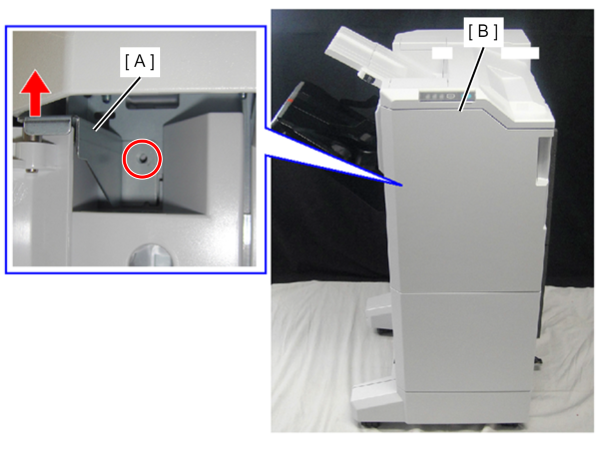
 : 4x8D/P
Open the front cover (A).
- Remove the screw that secures the belt (B).
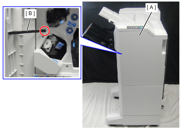
- : 3x8DC/BK
- Remove one screw and slide the cover hinge (A) upward to remove it.
- Remove the front cover (B).
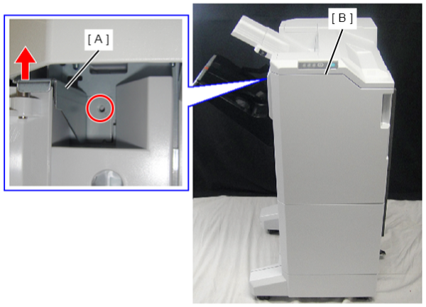
- : 4x8D/P
- Remove one screw and remove the front cover lower (B) and washer (A).
- Remove the washer (A).
- Remove the front cover lower (B).
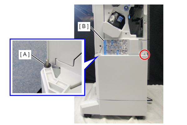
- : 4x10DC
- Remove 3 screws and the Front Inner Cover, Upper (A).
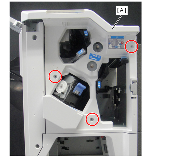
- : 4x10DC
- Remove the one screw.
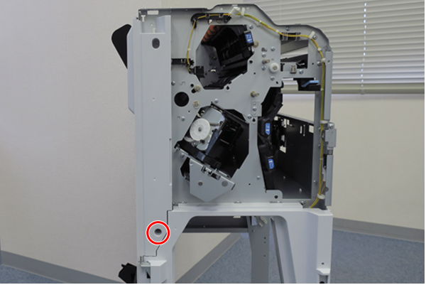
- : 4x10DC
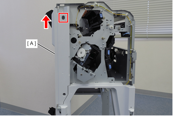
Slightly lift the front inner cover sub (A) to release the hook and remove it.
Insert a flathead (-) screwdriver under the lever of the staple cover (A) and lift it upward to unlock it.
- Open the staple cover (A).
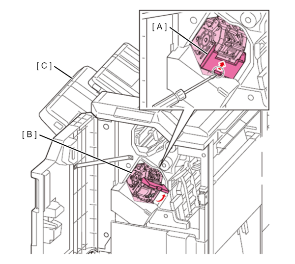
- Remove 2 connector of Stapler Unit (A).
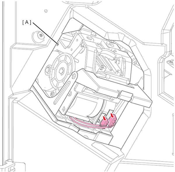
Lift the front of the stapler unit (A) to release the hooks and remove the stapler unit (A).
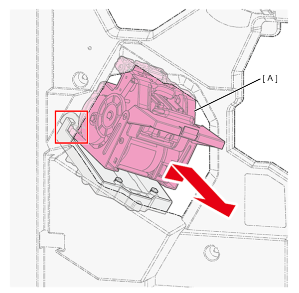
 Check Point / チェックポイント
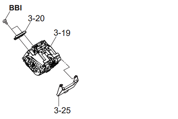
The ASP (3-19) Stapler Unit does not come with a guide stapler (3-20) and cover stapler (3-25), so when replacing the Stapler Unit, remove them from the old Stapler Unit and attach them to the new one.
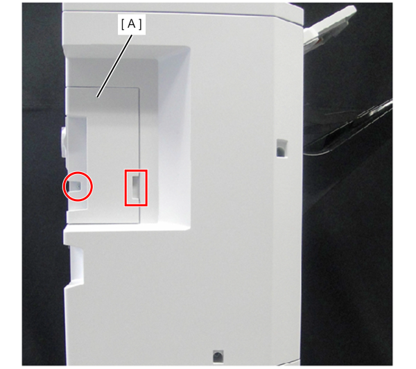
Remove 1 screw of the Rear Cover, Sub (A).
- Put your finger on the recess of the rear cover, sub (A) and open it to the left to remove it.
- : 4x10DC
Remove 3 screws of the Rear Cover, Upper (A).
- Slightly raise the top cover (B) and remove the rear cover, upper (A).
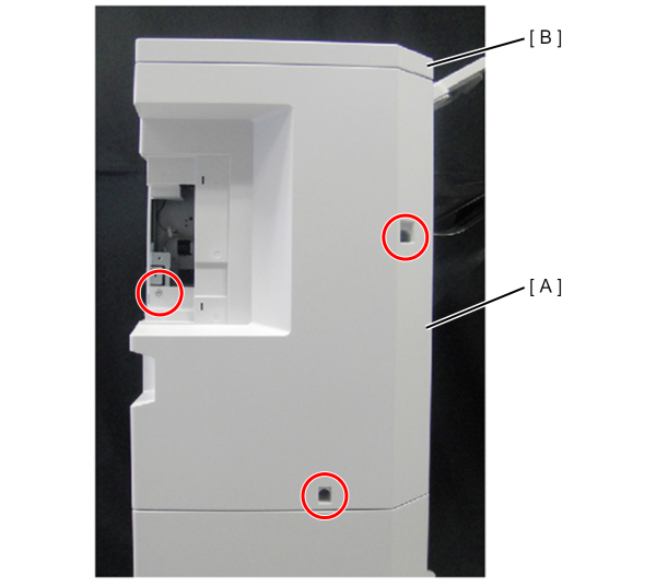
- : 4x10DC
- Remove 2 screws and remove the Rear Cover, Lower (A).
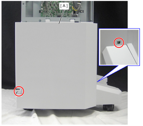
- : 4x10DC
- Release the tabs (x2) and remove the Lower Tray (A) upwards.
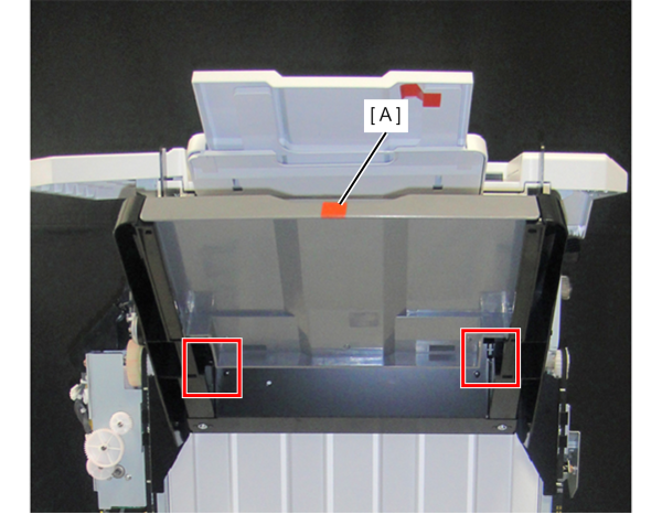
- Rotate the gear (A) of the Tray Lifting Gear Block counterclockwise using a screwdriver (B) or the like to lower the tray mounting frame (C).
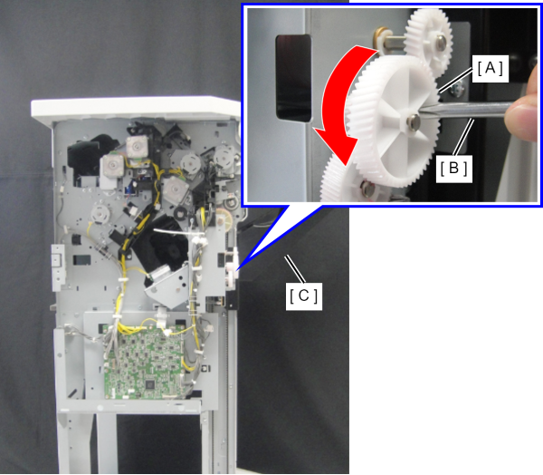
- Remove the 6 screws and remove the part (A) of the tray mounting frame.
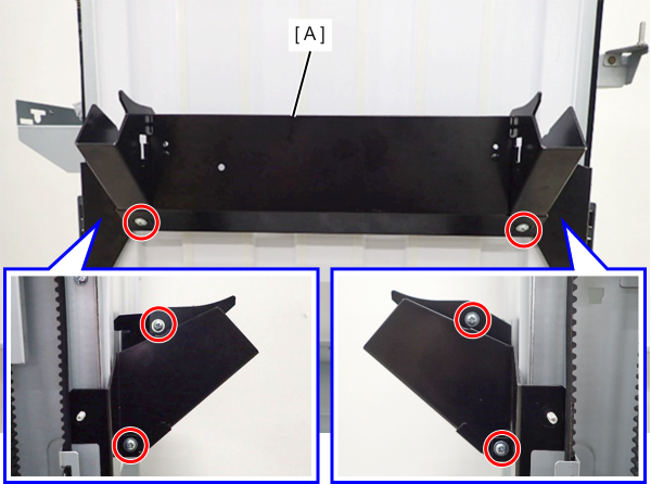
 : 4x10DC
- Retract the tray mounting frame (A) to the front side and rear side respectively.
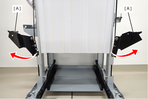
- Remove the 6 screws that secure the Left Side Lift Guide Cover (A).
- With the tray mounting frame (B) lowered to bottom, slide the Left Side Lift Guide Cover (A) upward and remove it.
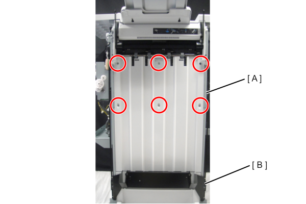
- : 3x8 DC/P
- Remove the cables (x2) (A) from the connectors.
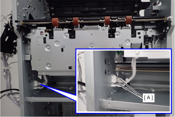
- Remove the one screw.
- Slide the metal plate (C) connecting the lower unit (A) and paper holding unit (B).
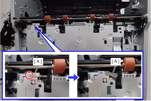
- : 3x8D/P
- Remove 5 screws.
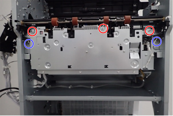
- : 3x8D/P
 : 4x8D/P
- Remove the paper holding unit (A).

- Remove the 2 cables (A) and FFC (B) from the connector (x3).
- Release the FFC from the clamp (x4) (C).
- Move the drive belt (D) to move the staple unit base (E) to the rear side.
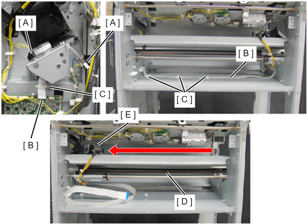
Remove the 4 screw.
- Lift the Stapler Rail Unit (A) and slide it to the front.
- After moving the Stapler Rail Unit (A) about halfway, rotate the Stapler Rail Unit (A) vertically and remove it.
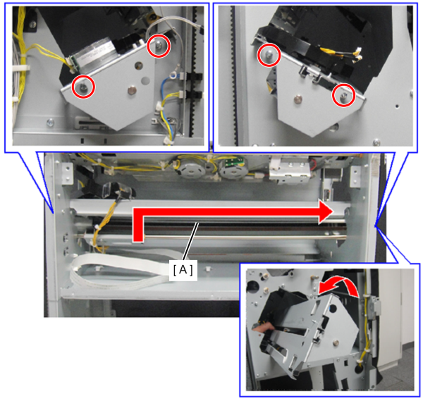
- : 4x8D/P