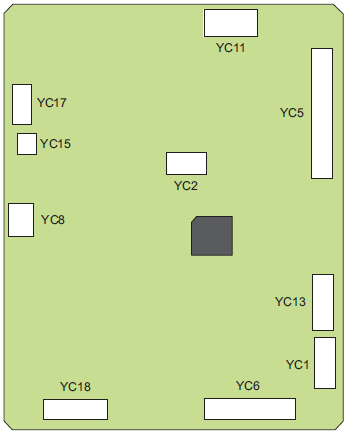
Controller Board
 Check Point / チェックポイント Check Point / チェックポイント |
|
- Remove the 4 screw.
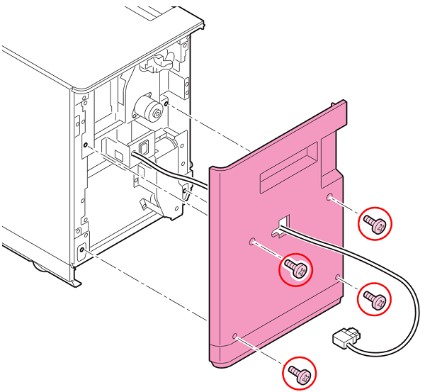
 : 4x10DC/P
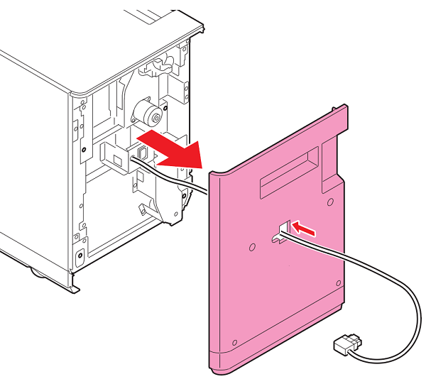
- Remove the Back Cover while pulling out the cable from the hole in the Back Cover.

 important / 重要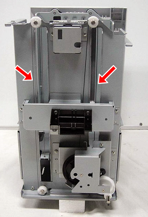
- Do not remove the Lift Wire parts except when there is trouble.
- The wires for lifting up are holding the front and back of the lift cassette horizontal so you need to perform horizontal adjustment if they are removed.
- Disconnect all connectors from the Controller Board.
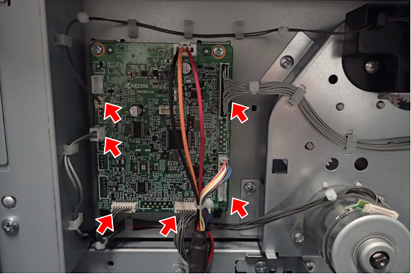
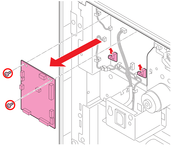
- Remove the 2 screws.
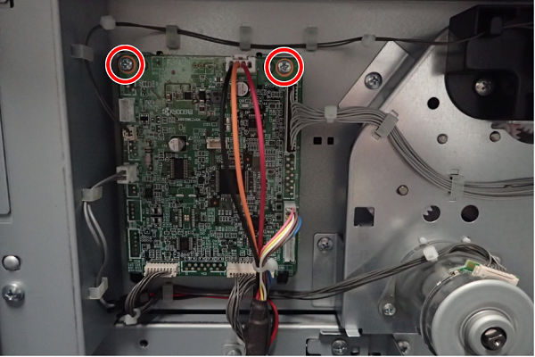
- : 3x8M/P
- Remove the Control Board from the hooks (x2).
 Assemble / 組み立て Assemble / 組み立て |
||||||||||||||||||||||||||||||||||||||||||||
|