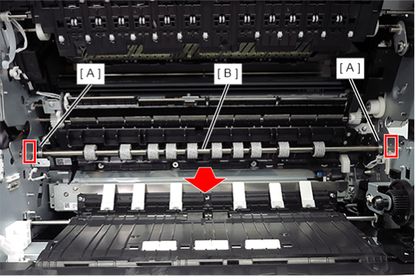
Registration Roller
- Remove the 2 screws and remove the Left Cover Upper (A).
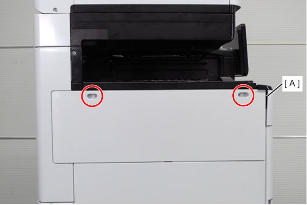
 : 3x10DW
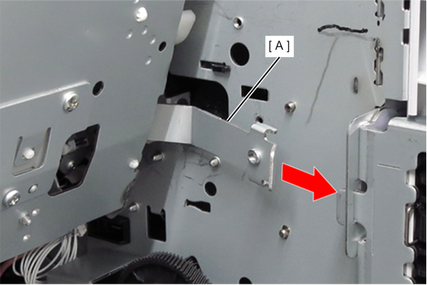
- Remove the two screws and slide the Left Cover Sub Upper (A) in the direction of the arrow to remove it.
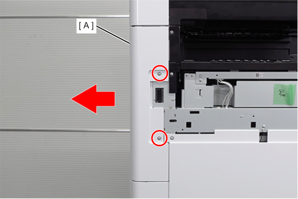
- : 3x10DW
- Remove the 4 screws and remove the right cover sub (A).
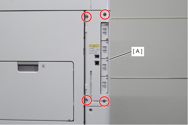
- : 3x10DW
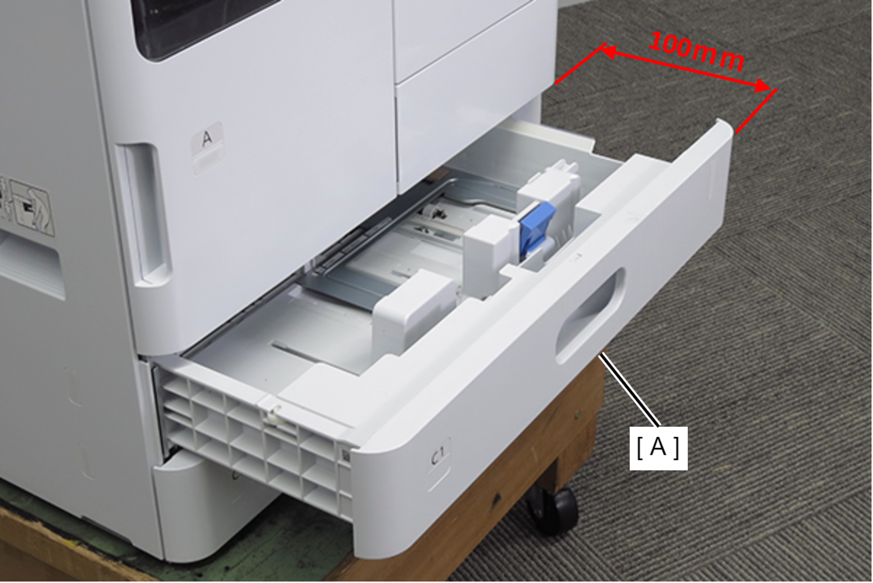
- Pull out the C1 cassette (A). (about 100mm)
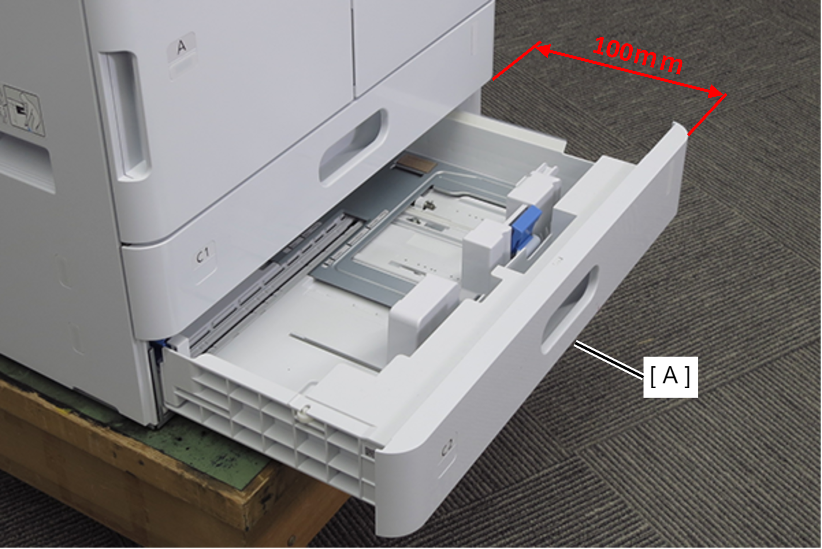
- Pull out the C2 cassette (A). (about 100mm)
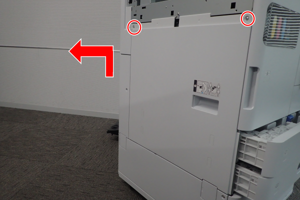
- Remove 2 screws and remove the Left Cover Lower (A) in the direction of the arrow.
- : 3x10DW
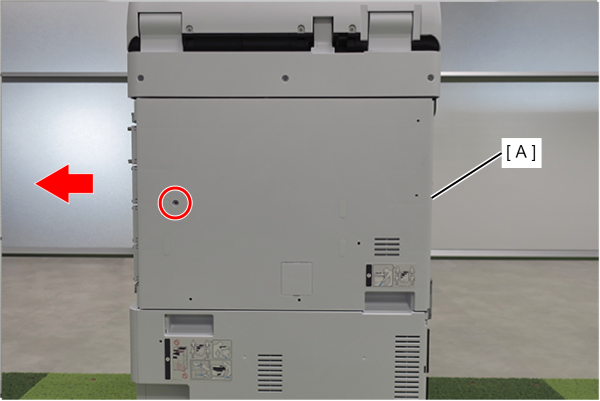
- Remove 1 screw and slide the rear cover (A) in the direction of the arrow to remove it.
- : 3x10DW
 Assembly / 組み立て
Align the 5 hooks on the rear cover with the 5 holes on the main unit and attach it.
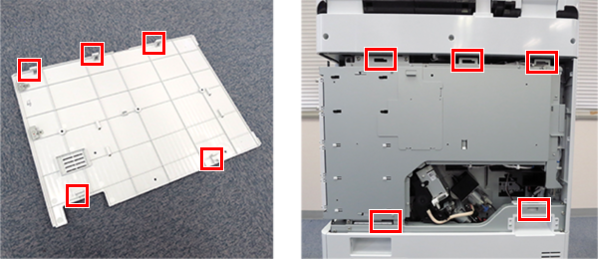
- Remove 1 screw and remove the Left Cover Sub Lower (A) in the direction of the arrow.
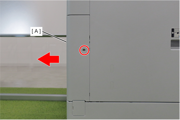
- : 3x10DW
- Remove 4 screws.
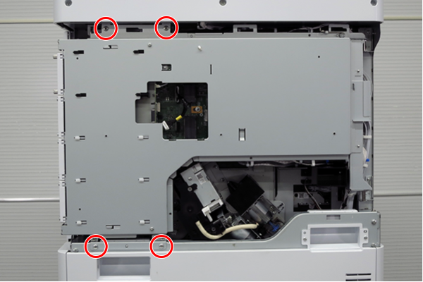
- : 4x8D
- Slightly lift the board box (A) to release the hook.
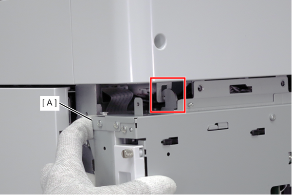
- Open the board box (A).
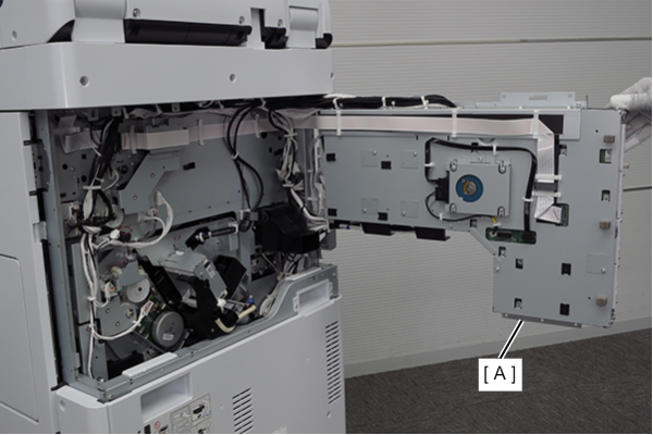
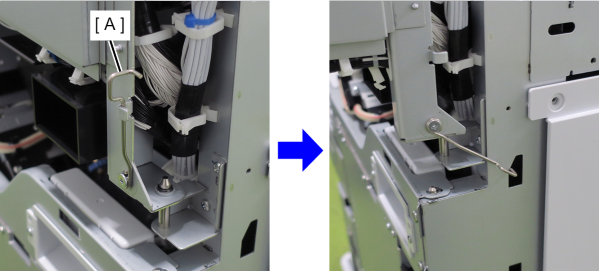
 Check Point / チェックポイント
- By hooking the hook (A) of the board box to the hole in the main body, the position of the board box is stabilized, making it easier to work.
- Do not close the circuit board box while hooking the hook (A) on the main unit. The frame may be deformed.
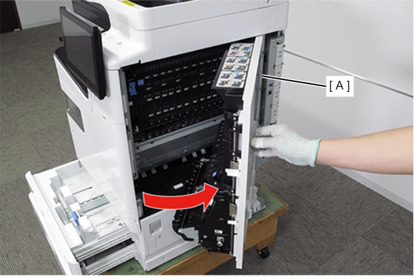
- Pull the lever to open the Right Door Unit (A).
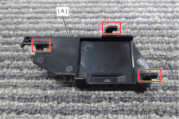
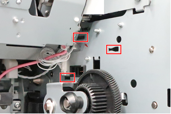
Follow the steps below to remove the connector cover (A).
1.Release the dowel.
2. Slide in the direction of the red arrow.
3. Slide in the direction of the blue arrow to release the hook.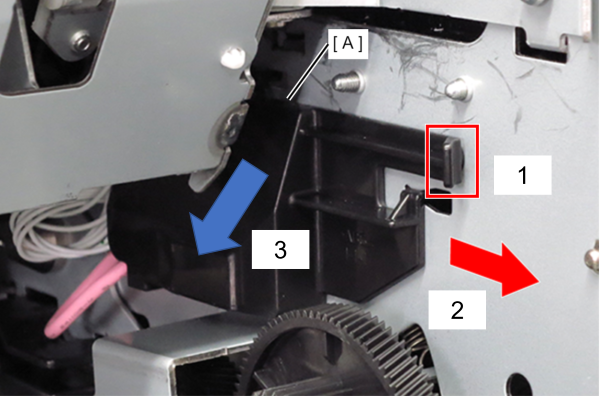
 Caution / 注意
Do not close the Right door unit (D1) with the belt holder removed and the belt unit lowered from its normal position.
The right door may not open. In this case, it is necessary to remove the Right door unit form the main unit.Assembly / 組み立てInsert the 3 hooks of the connector cover (A) into the positioning holes on the main unit.
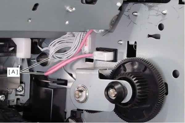
- Remove the two cables (A) from the connectors.
 Assembly / 組み立て
Connect the pink cable in the direction shown in the figure.
- Remove the two screws and remove the left belt holder (A) toward you.
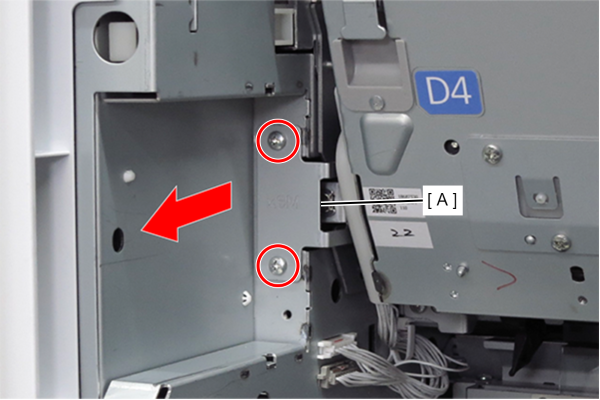
- : 3x6D
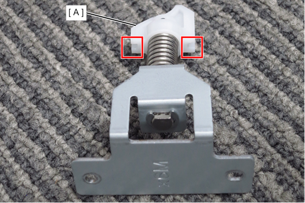
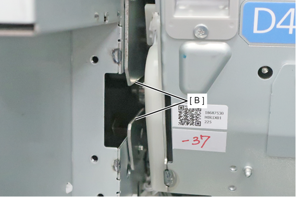
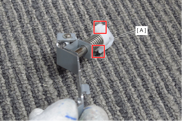
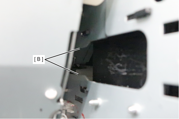
Assembly / 組み立てFit the body frames plates (B) into the two grooves of the belt holder left (A).
- Remove the one screw.
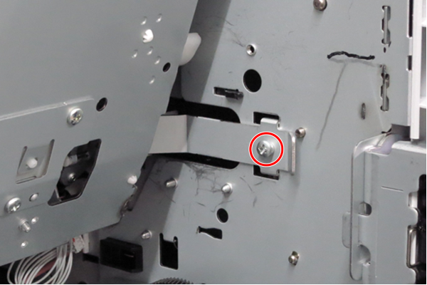
- : 3x6D
- Unlock the 2 hooks on the right belt holder (A) by following the steps below.
1. Slide the belt holder (A) in the direction of the red arrow.
2. While sliding in the direction of the red arrow, move it in the direction of the blue arrow to release 2 hooks.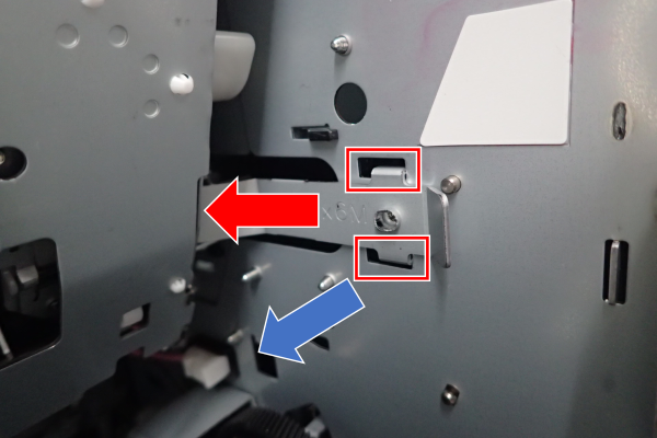
- Slide the belt holder right (A) forward to remove it.
 Caution / 注意
Do not close the right door unit (D1) with the belt holder removed and the belt unit lowered from its normal position.
The right door may not open.Assembly / 組み立てFit the body frames plates (B) into the two grooves of the belt holder right (A).
- Remove one screw and remove the belt connector left cover (A).
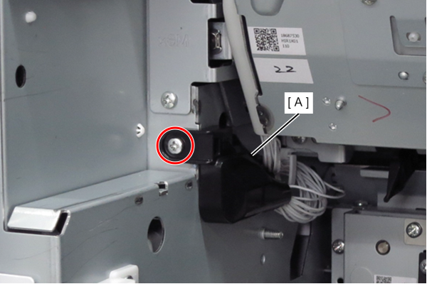
- : 3x8D
Assembly / 組み立てAttach thebelt connector left cover (A) by inserting the hook into the hole in the body frame and putting the cable (B) inside (C).
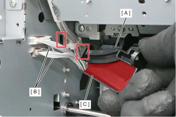
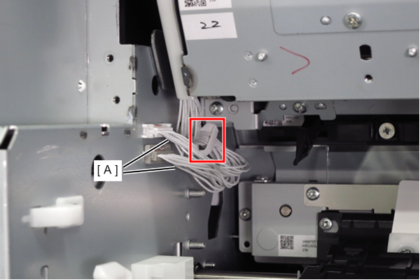
- Remove the 2 cables (A) from the connector and release them from the clamps.
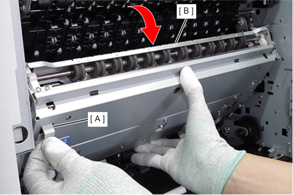
- Pull the lever (A) to open the belt unit (B).
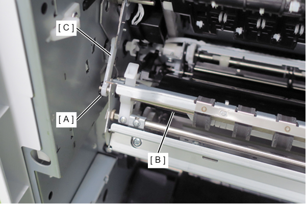
- Remove the C-ring (A).
- Remove the belt arm (C) from the shaft of the Belt unit (B).
 Caution / 注意
When the belt arm (C) is removed, the Belt unit (B) will drop.
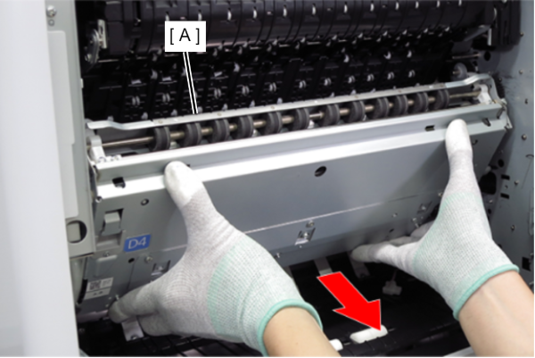
Remove the belt arm (C) while holding the Belt unit (B). While holding the belt unit (A) with both hands, pull it out horizontally to the front.
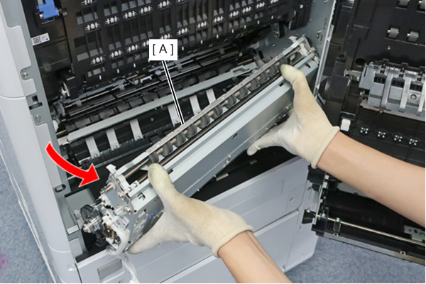
- Tilt the left hand side diagonally and remove the belt unit (A).
 Caution / 注意
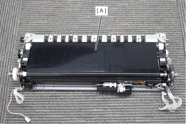
Do not touch the belt surface (A) of the belt unit.
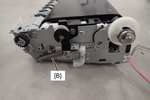
Be careful not to lose the spring (B) on the side of the belt unit by dropping it.
 Assembly / 組み立て
Insert the two bearings of the belt unit (A) into the frame guides.

- Remove the one screw.
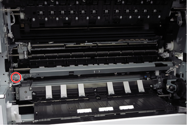
- : 3x8D
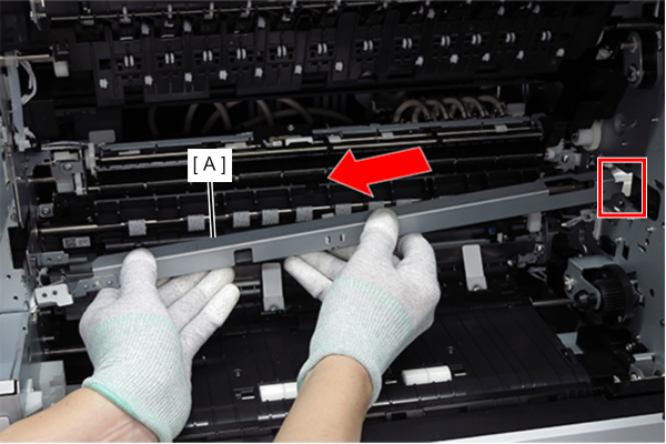
- Slide the registration roller support (A) in the direction of the arrow, pull out the tab, and remove it.
- Remove one screw and remove the Rear cover lower (A) in the direction of the arrow.
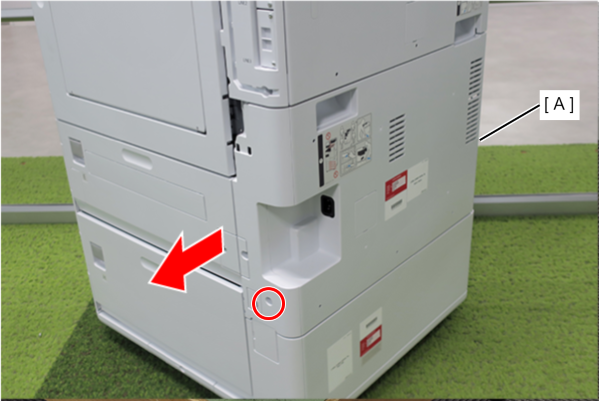
- : 3x10DW
- Remove 8 screws and open the power supply box (A).
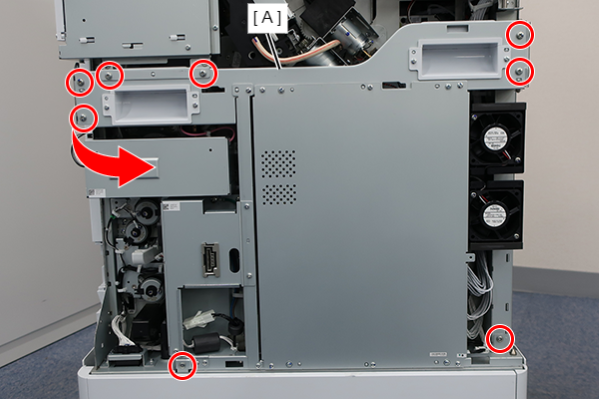
- : 4x8D/P
- Disconnect the cable (A) from the connector.
- Remove the C-ring (B).
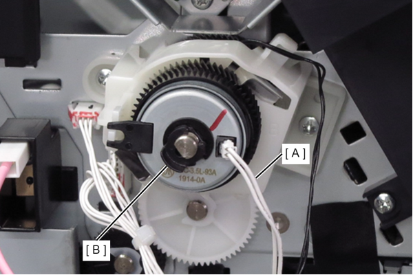
- Remove the registration roller brake clutch (A).
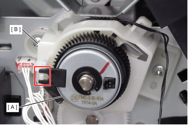 Assembly / 組み立て
Set the recess of the registration roller clutch (A) to the protrusion of the cover (B).
- Release the cable (B) from the cover (A) guide.
- Remove the 2 screws and remove the cover.
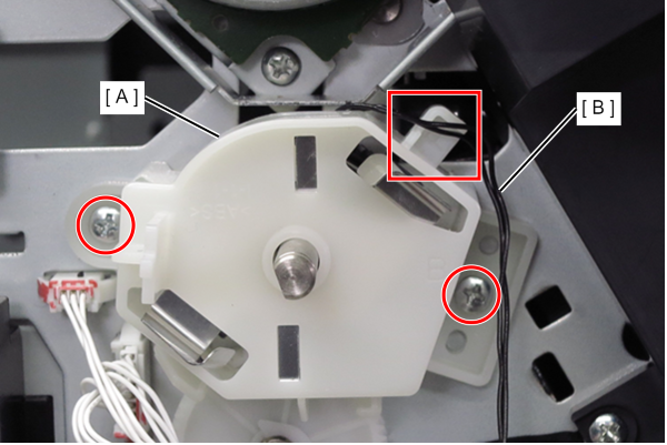
- : 3x8D
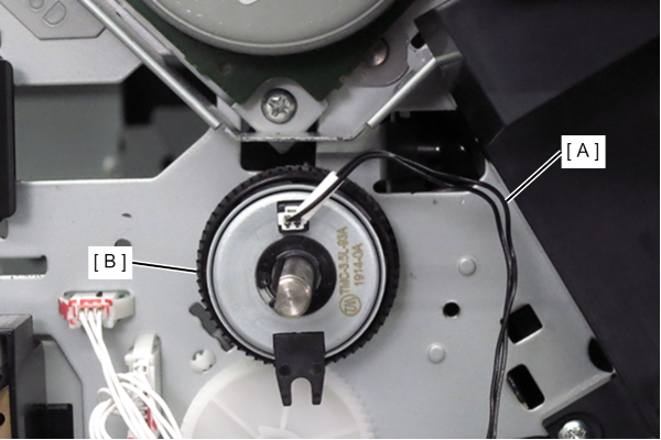
- Disconnect the cable (A) from the connector.
- Remove the registration roller clutch (B).
- Pull the lever to open the D3 Unit (A).
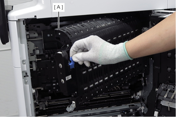
- Follow the steps below to remove the anti static brush connector cover (A).
1.Press and lift the hook (red) to release the dowel (blue).
2. Remove the connector cover (A) from the main unit, avoiding the belt arm (B).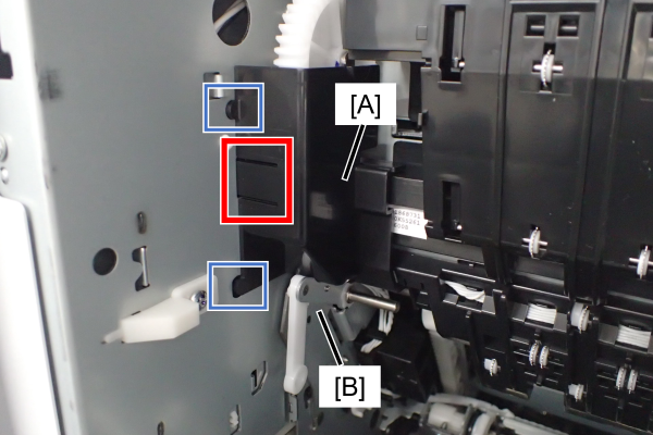
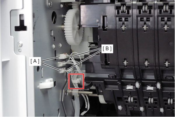
- Remove the two cables (B) from the two connectors (A).
- Release the cables from the clamp.
- Release the cables (B) from the three hooks on the cable guide (A) and out of the guide.
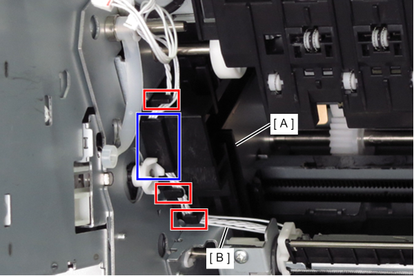
- Remove the screw that secures the anti static brush unit (A), and slide it in the direction of the arrow.
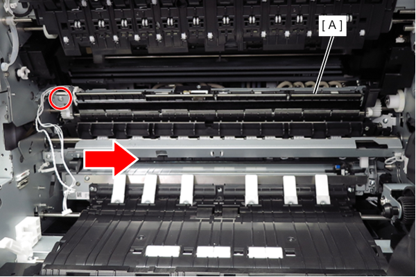
- : 3x8D
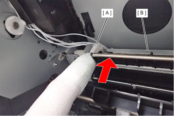
Assembly / 組み立てWith the left cam (A) pushed up, slide the anti static brush unit (B) in the direction of the blue arrow to attach it.
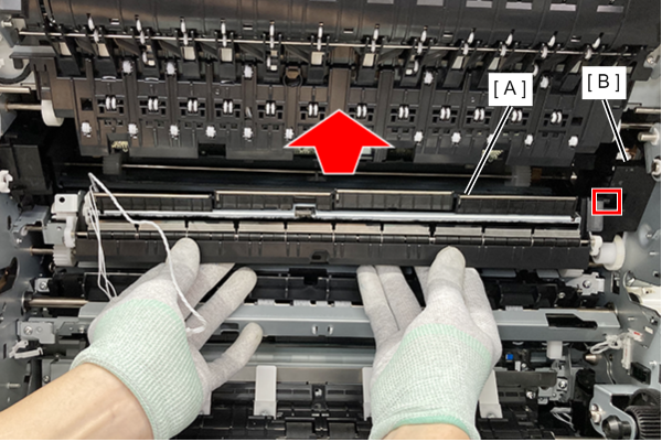
- Slide the anti static brush unit (A) upward, pull out the shaft of the anti static brush unit (A) from the groove of the guide (B), and remove it.
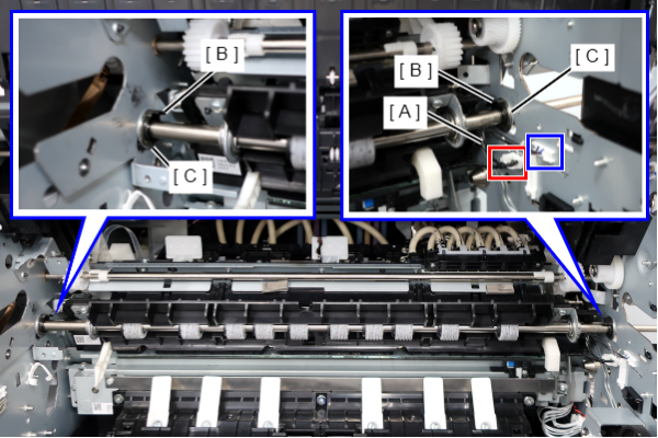
- Release the cable (A) from the clamp and remove it from the connector.
- Remove 2 C-ring (B) and remove 2 bearings (C) from the frame.
- Remove 4 screws.
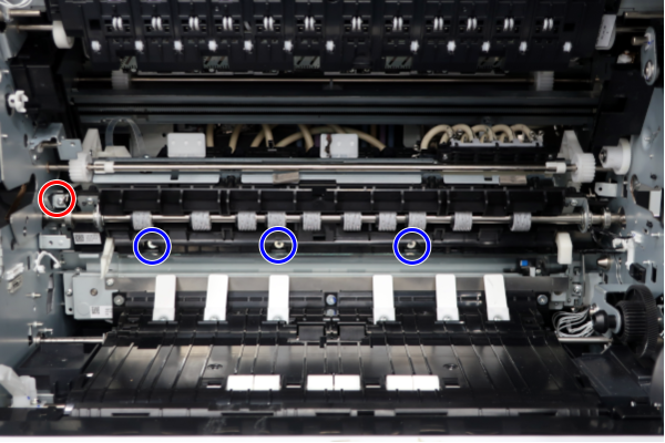
 : 3x8D/P
 :3x5D/TBD
- Move the Registration Unit (A) in the direction of the red arrow and remove it in the direction of the blue arrow.
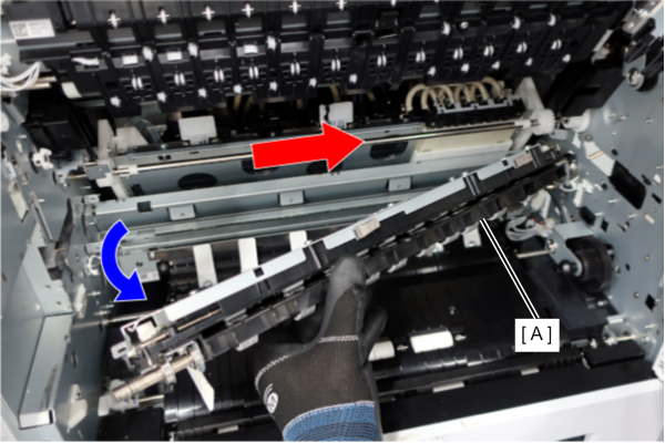 Assembly / 組み立て
When installing the Registration Unit (A), be sure to check in advance that the Registration Unit connector (B) is correctly routed.
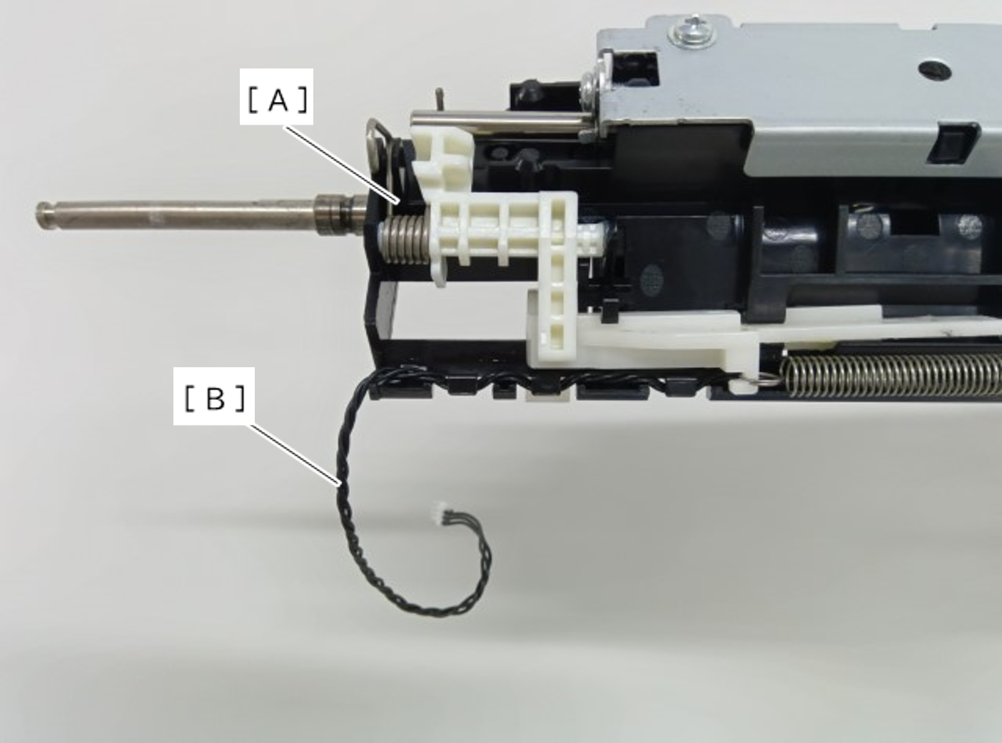
Install the Registration Unit according to the following procedure.
1. Hold the Registration Unit (A) with the roller surface facing down.
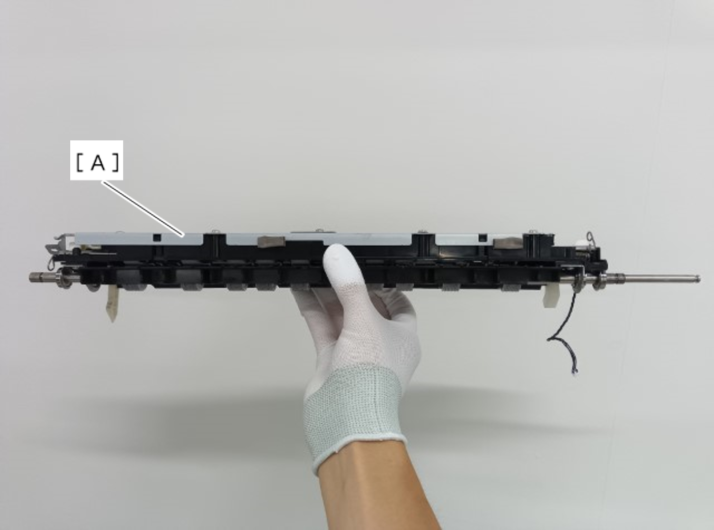
2. Insert the right roller shaft of the Registration Unit (A) into the hole in the Main Frame.
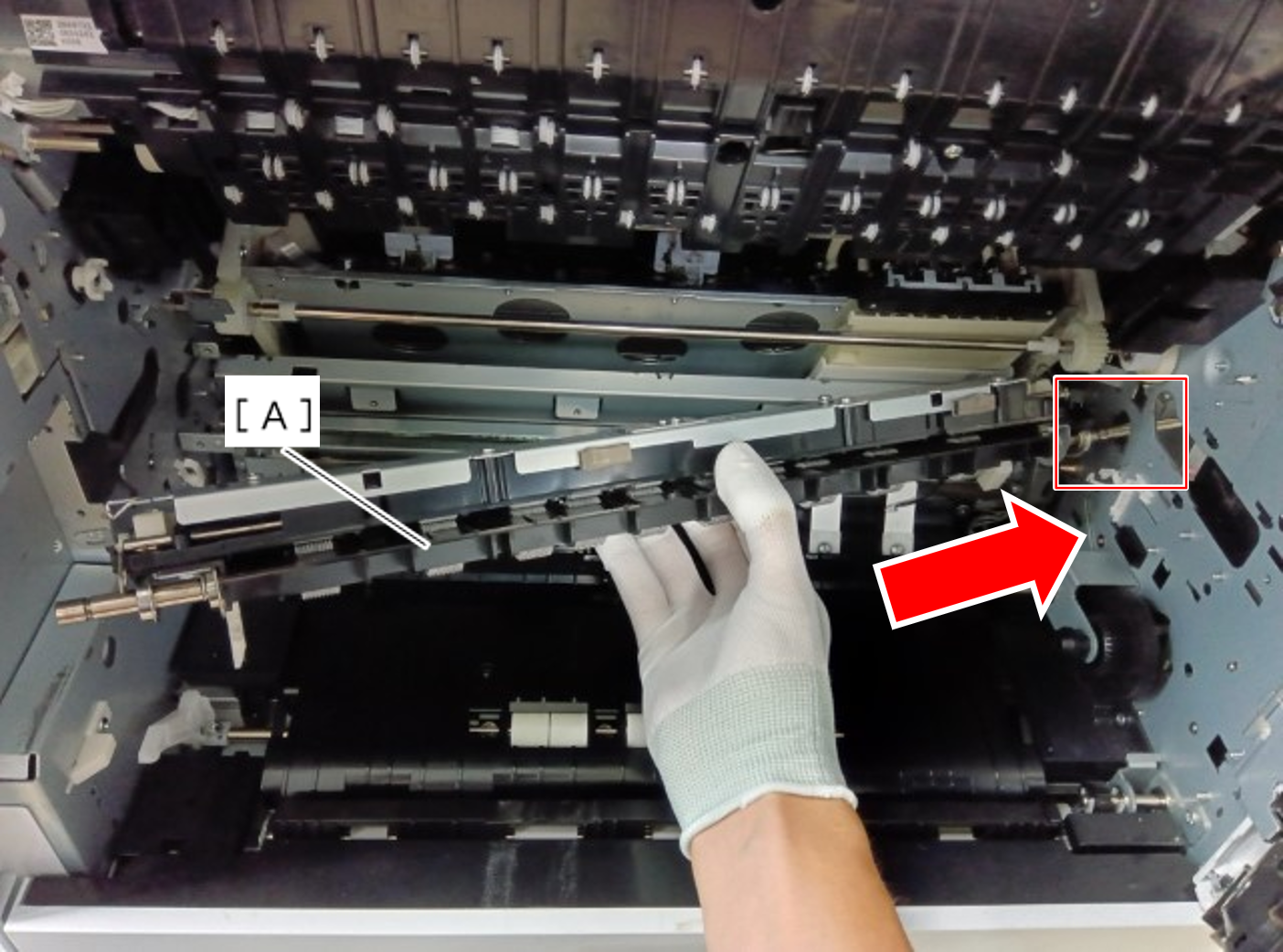
3. Lift the Registration Unit (A) being careful to avoid the protrusions (B) on the Main Frame, then push it in and insert the left roller shaft into the hole (C) on the Main Frame.
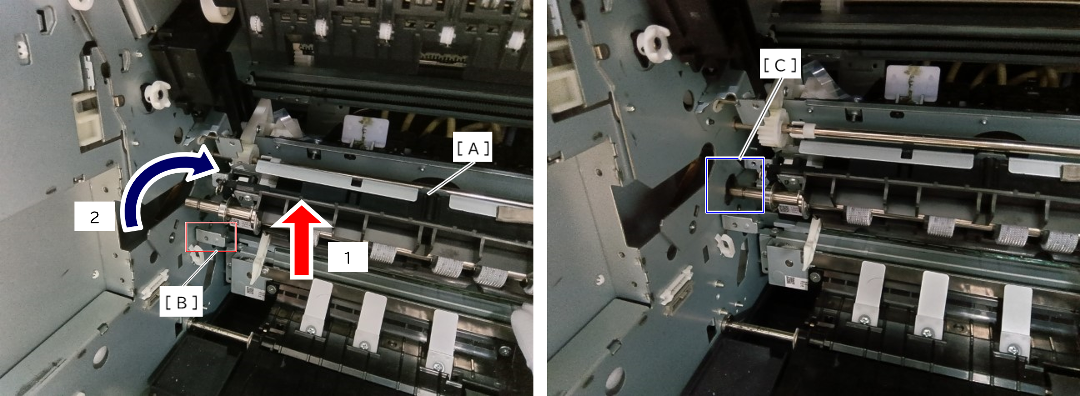
4. Slide the Registration Unit (A) in the direction of the arrow to install it.
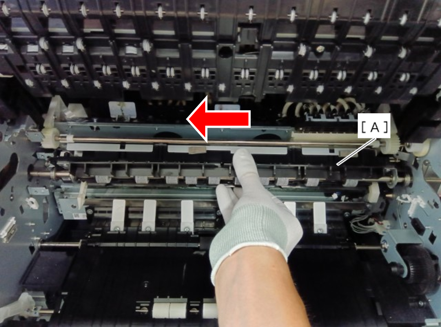
5. Tighten the four screws.
- : 3x8D/P
- : 3x5D/TBD
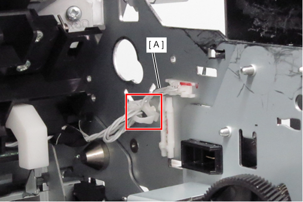
- Disconnect the cable (A) from the connector.
- Release the cable (A) from the clamp.
- Remove 5 screws. (SX:, SX:)
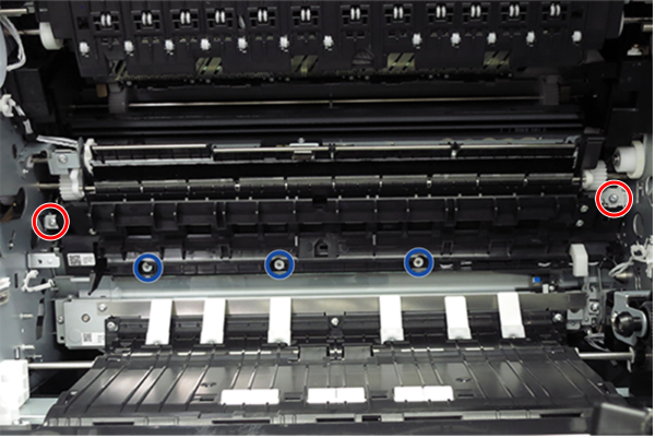
- SX: ---
- SX: ---
- Remove the registration unit (B) while avoiding the anti static brush unit (A).
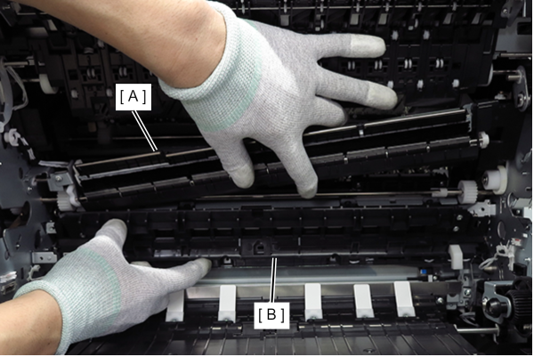
- Remove 2 C-ring (A).
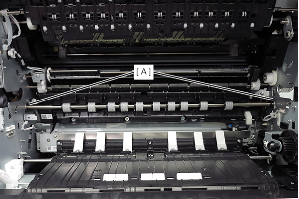
- Move the 2 bearings (A) inward.
- Move the registration roller (B) forward and pull it out of the hole in the frame.