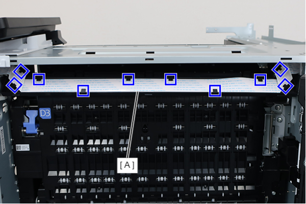
Panel FFC
- Remove the 3 screws and remove the SCN rear cover (A) in the direction of the arrow.
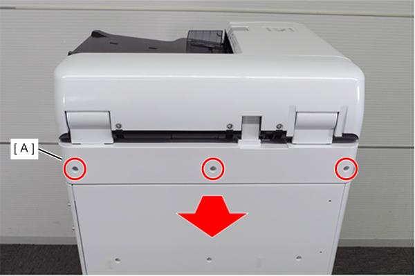
 : 3x10DW
 Assembly / 組み立て
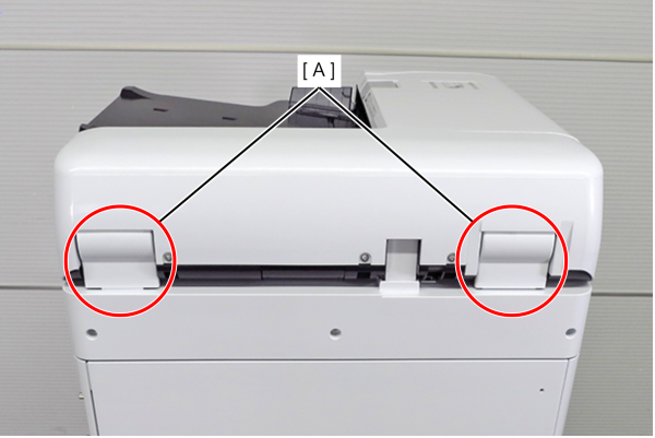
When installing the SCN rear cover, be careful not to get the hinge cover (A) of the ADF unit caught.
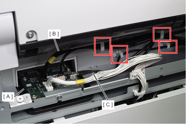
- Remove the cables (B, C) from the connectors (CN300, CN302) on the SCN main board (A).
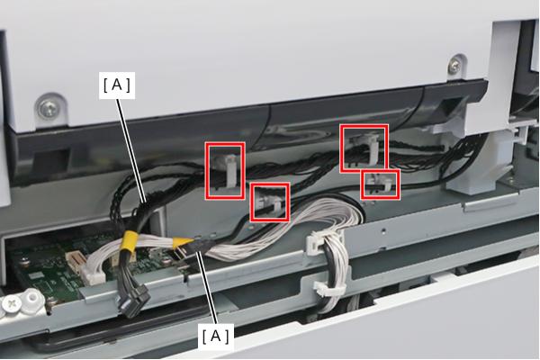
- Release the 2 cables (A) from the four clamps.
- Remove 5 screws.
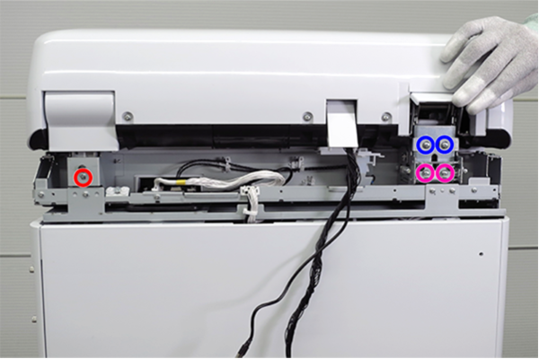
- : 3x12DC
 : 4x6D
 : 4x8D
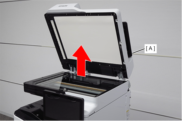
- Remove the ADF unit (A) upwards.
- Remove the 2 screws and remove the Panel Upper Cover (A).
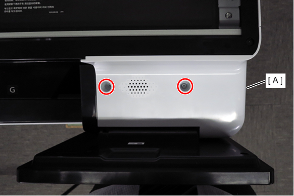
- : 3x10DW
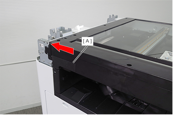
- Remove the SCN left cover sub (A) by sliding it in the direction of the arrow.
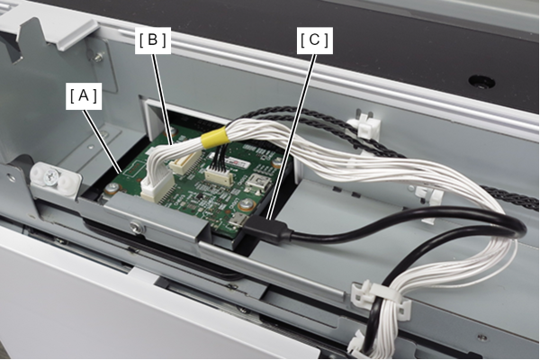
- Remove the cables (B, C) from the connectors (CN307, CN400) on the SCN main board (A).
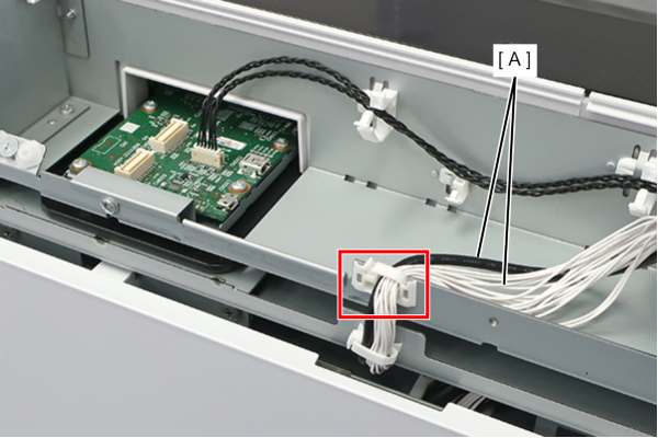
- Release the two cables (A) from the clamp.
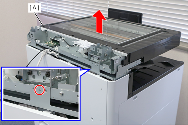
- Remove the three screws on the front side.
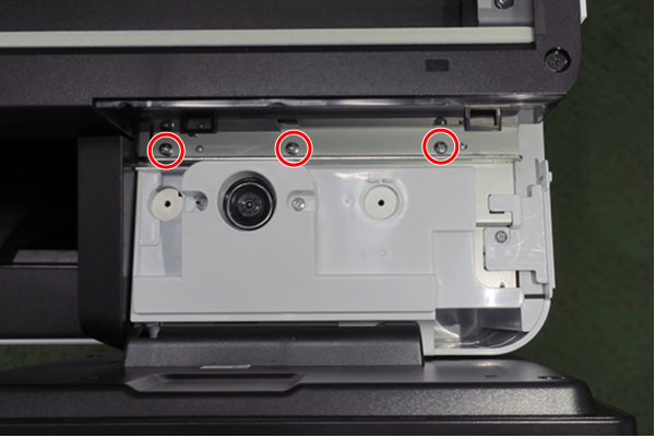
- : 3x8D
- Remove the five screws that secure the SCN unit (A).
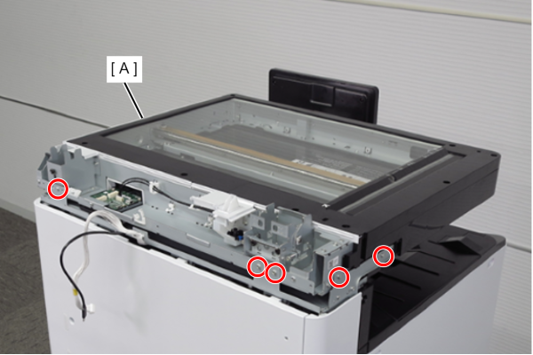
- : 3x8D
- Release the dowel and remove the SCN unit (A) upwards.
- Remove the 2 screws and remove the Left Cover Upper (A).
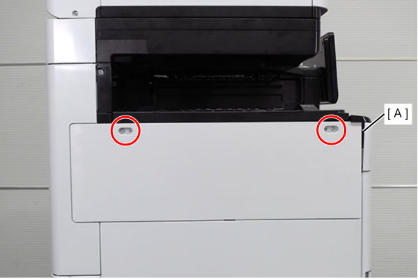
- : 3x10DW
- Remove one screw, and remove the front cover upper (A) in the direction of the arrow while pressing the hook.
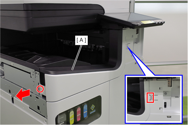
- : 3x10DW
- Release the 2 dowels with a flathead screwdriver and remove the Front Cover (A).
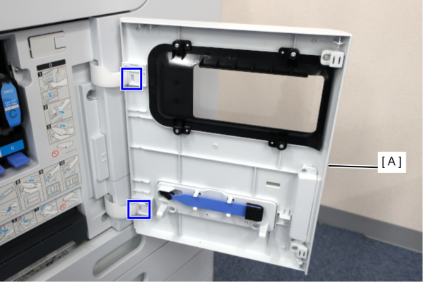
- Slide the front decorative cover upper (A) in the direction of the arrow to remove it.
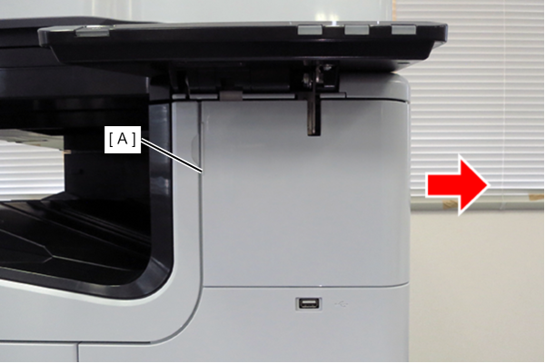
- Release the hook and remove the Front Decorative Cover Lower (A) in the direction of the arrow.
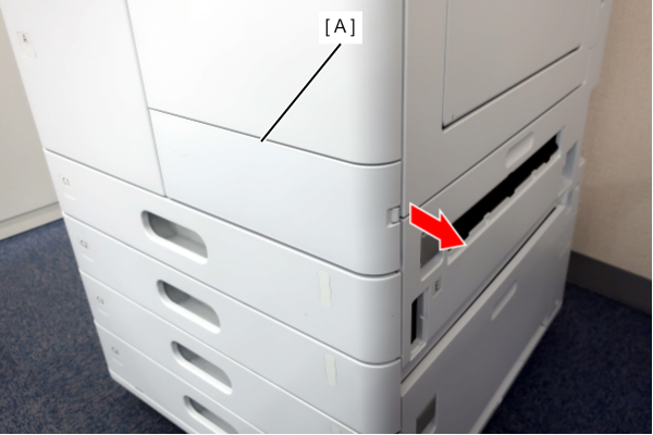
- Remove 6 screws and remove the Front Right Cover (A).
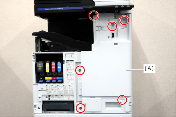
- : 3x10DW/P
- Remove the two screws and slide the Left Cover Sub Upper (A) in the direction of the arrow to remove it.
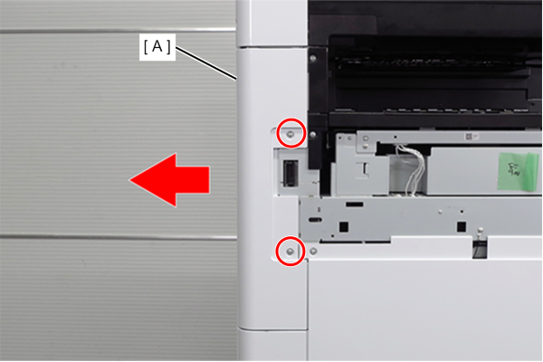
- : 3x10DW
- Remove the 4 screws and remove the right cover sub (A).
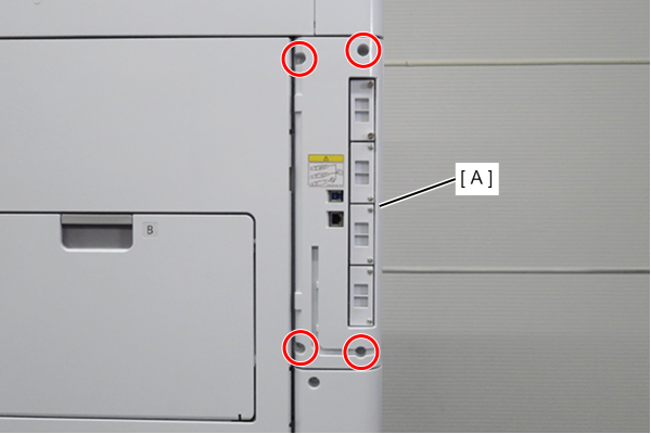
- : 3x10DW
- Remove 1 screw and slide the rear cover (A) in the direction of the arrow to remove it.
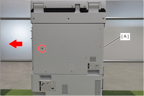
- : 3x10DW
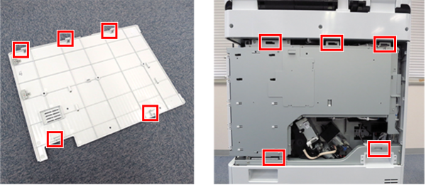
Assembly / 組み立てAlign the 5 hooks on the rear cover with the 5 holes on the main unit and attach it.
- Disconnect the cable (A) from the connector.
- Remove 3 screws.
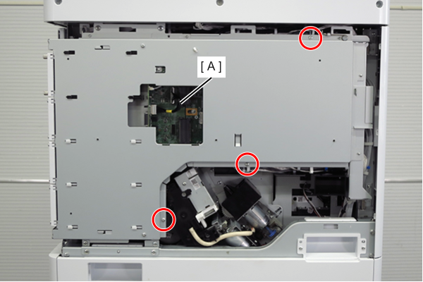
- : 3x8D
 Caution / 注意
When tightening screws, make sure that the screw holes are aligned before tightening.
If the screw holes do not match, the threads may be stripped.
- Lift the handle to release the hook.
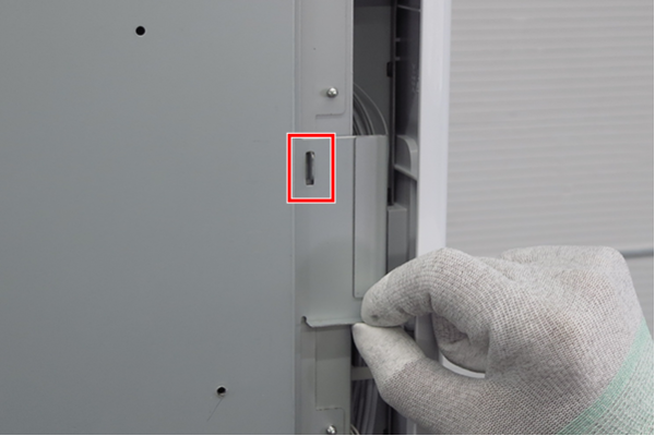
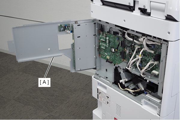
- Open the board box upper case (A).
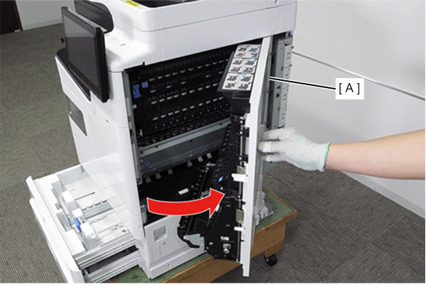
- Pull the lever to open the Right Door Unit (A).
- Remove the FFC cable (A) from the connector and move to the right.
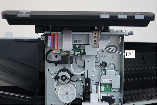
- Remove the FFC clamp and disconnect the FFC cable (A) from the board.
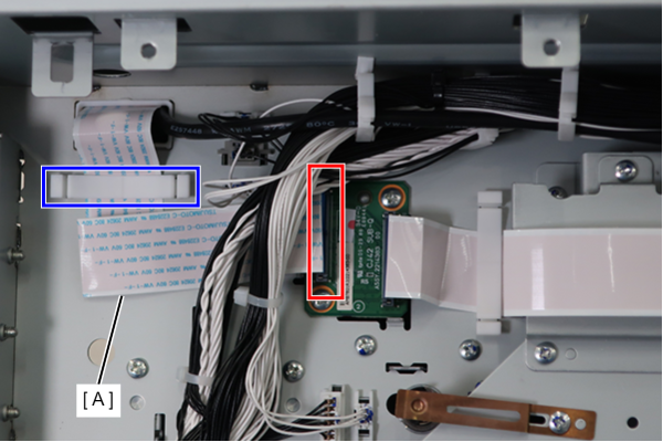
- Release the hook and remove the connector cover (A) in the direction of the arrow.
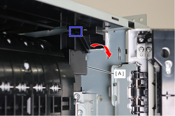 Assembly / 組み立て
Align the 2 dowels (A) with the two holes (B), and attach the FB cable cover (C) while rotating.
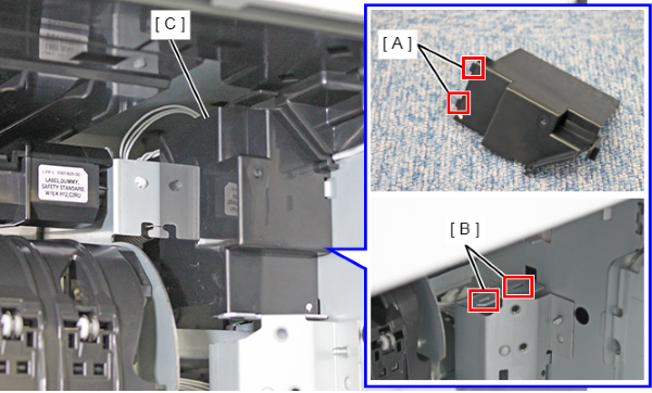 Caution / 注意
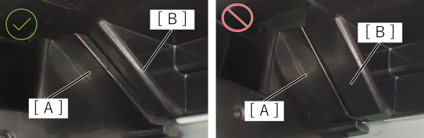
- Confirm that the FB cable cover (A) is hooked under the FR holder (B).
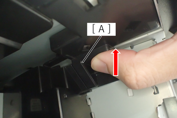
If the FB cable is too deep, it can be restored by raising the FR holder (A).
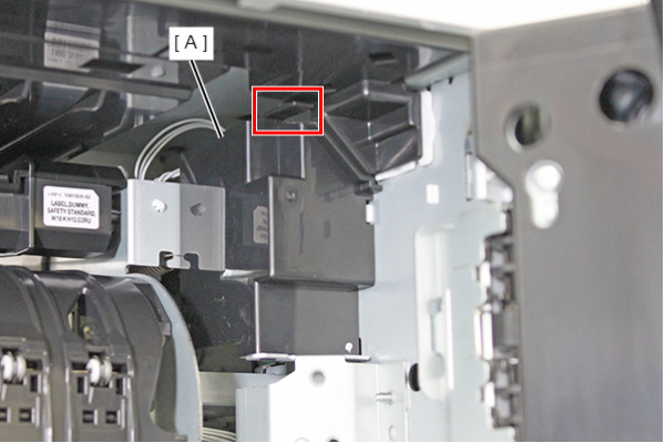
Make sure that the hook of the FB cable cover (A) is engaged.
- Confirm that the FB cable cover (A) is hooked under the FR holder (B).
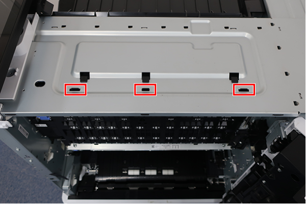
Remove the 3 hooks and remove the cable holder.
 Assembly / 組み立て
After fitting the 3 protrusions on the lower side into the 3 holes in the frame, fix the 3 claws on the upper side to the 3 holes in the rear of the frame.
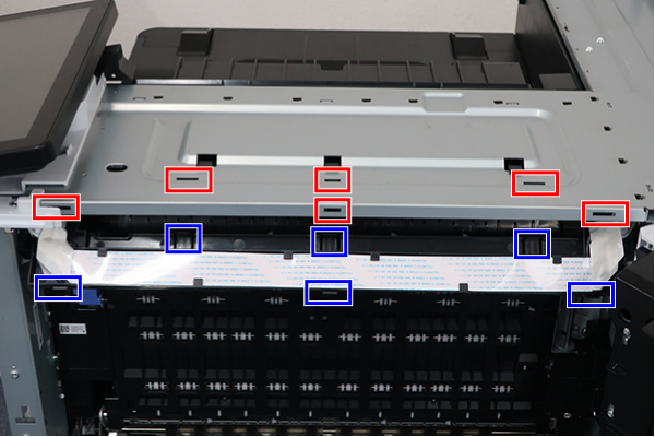
- Remove 2 pieces of tape.
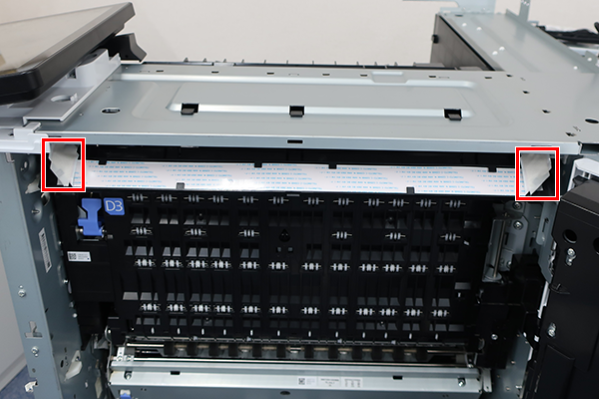 Assembly / 組み立て
After installing the FFC cable, secure in place with tape.
- Release the 10 hooks and remove the Panel FFC.