
Torque Limiter
 Check Point / チェックポイント Check Point / チェックポイント |
When replacing this part, you need to run the menu from the service support mode before replacing it. |
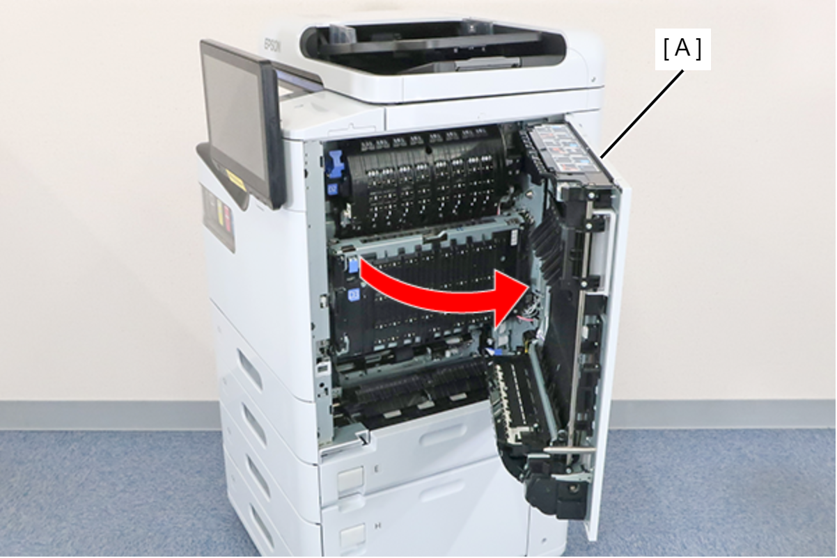
- Open the right door unit (A).
 Assembly / 組み立て
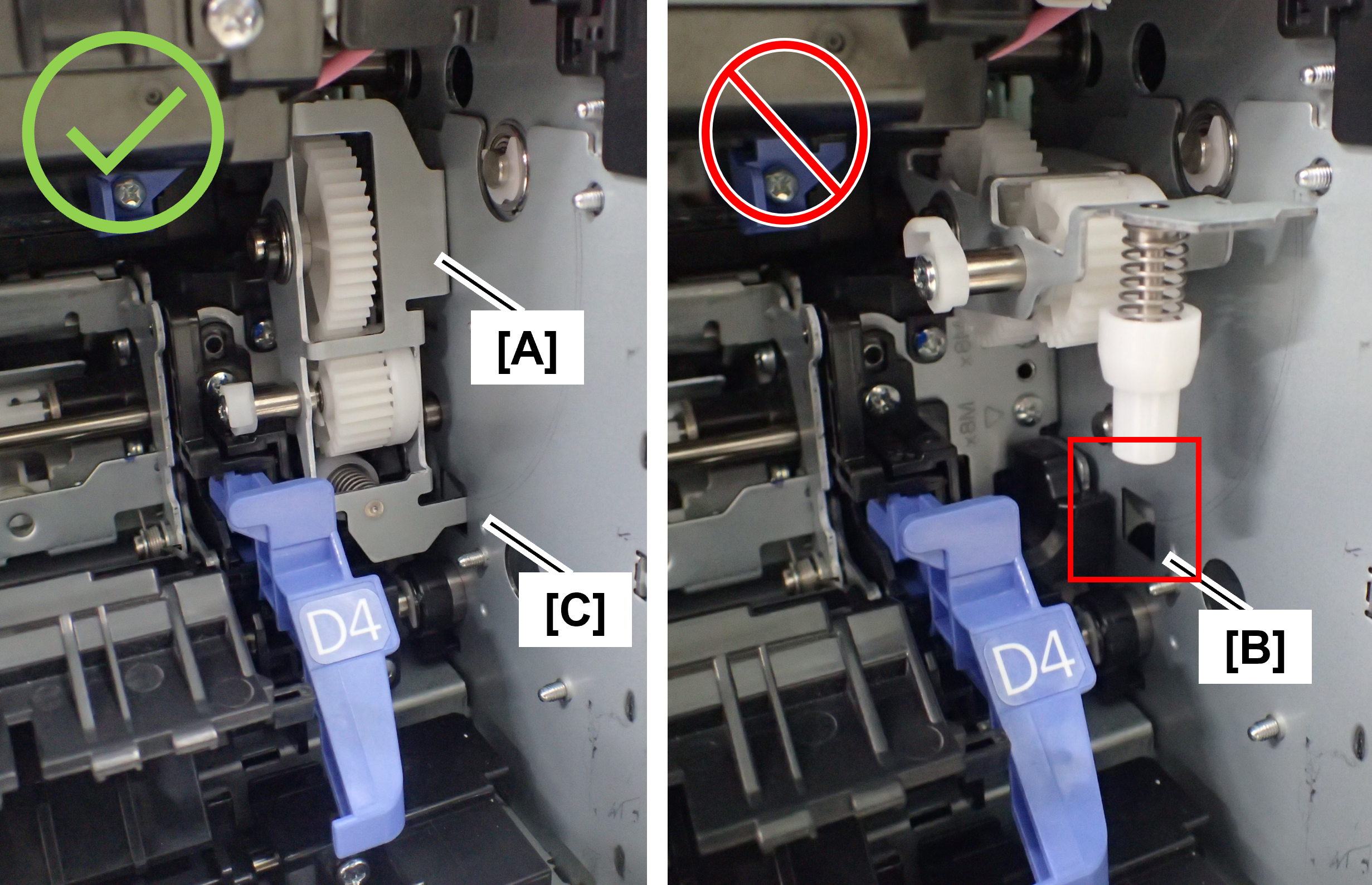
When closing the right door unit, it may not close due to interference with the tumbler (A) that was tilted toward the front when other parts were repaired.
If the right door unit does not close, check the position of the tumbler, and if it is protruding toward the front, fit the tip of the tumbler plate (C) into the hole (B) in the main unit.
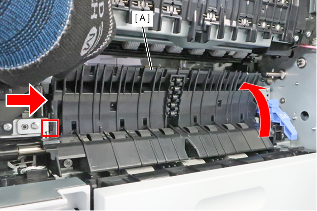
- Raise the Guide PF Inner (A) and push it in the direction of the arrow to release the dowel, then remove the Guide PF Inner.
 Assembly / 組み立て
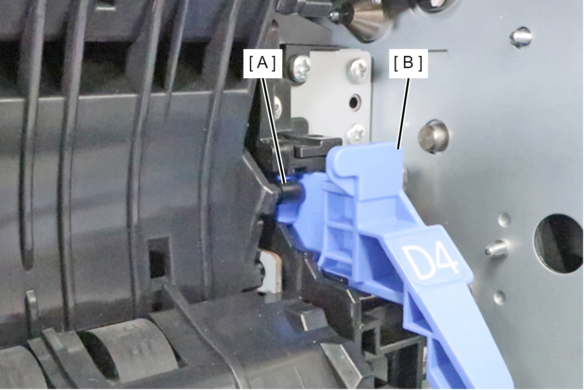
Put the shaft (A) on the inward side of the lever (B) and attach it.
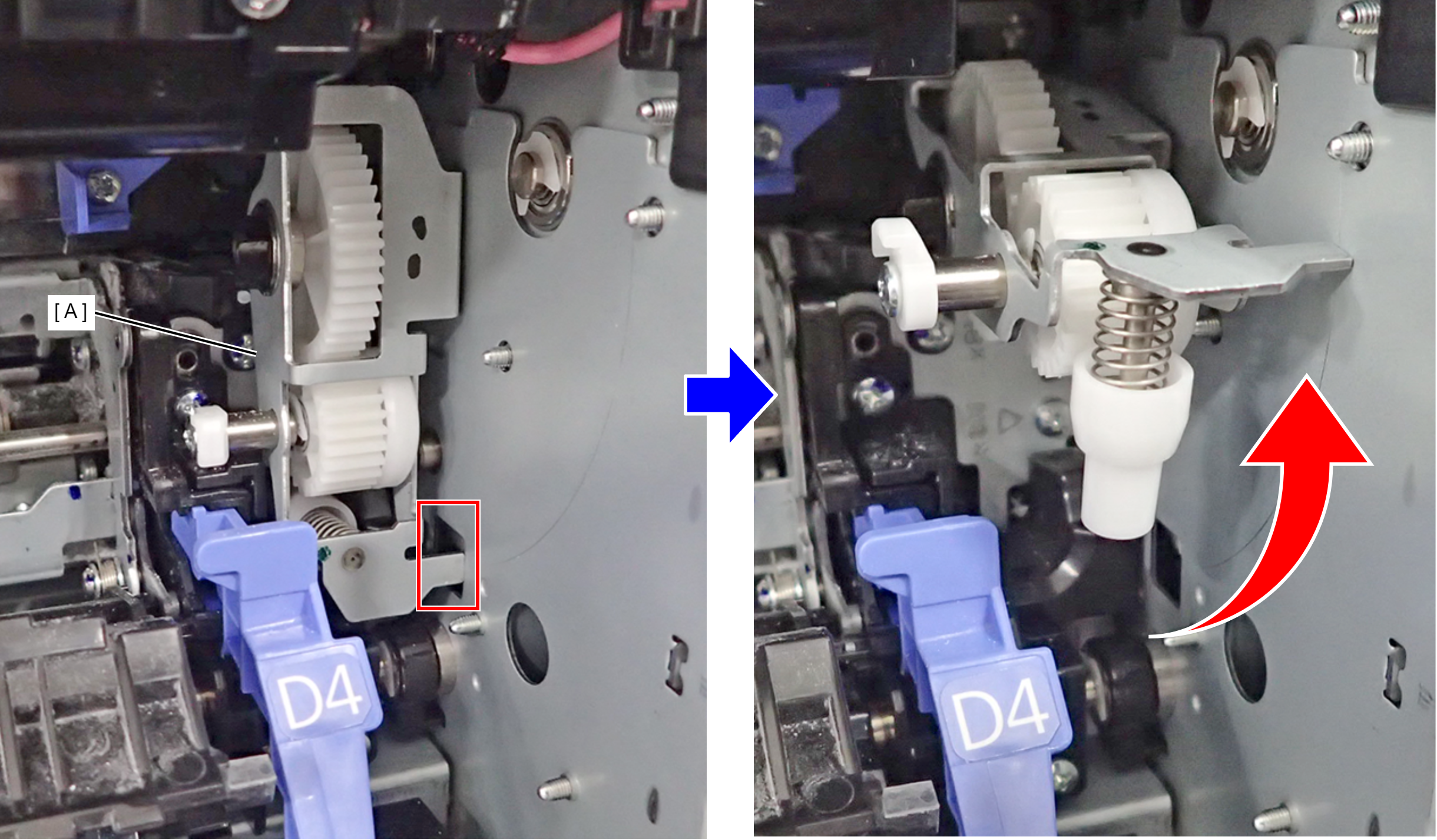
- Pull out the tab of the Tumbler (A) from the hole, then raise the Tumbler.
- Remove the 2 screws that secure the Guide PF Inner Lever Assy (A).
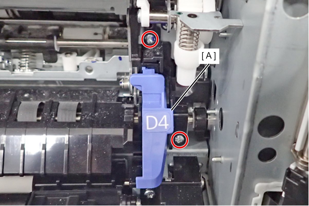
 : 3x8M
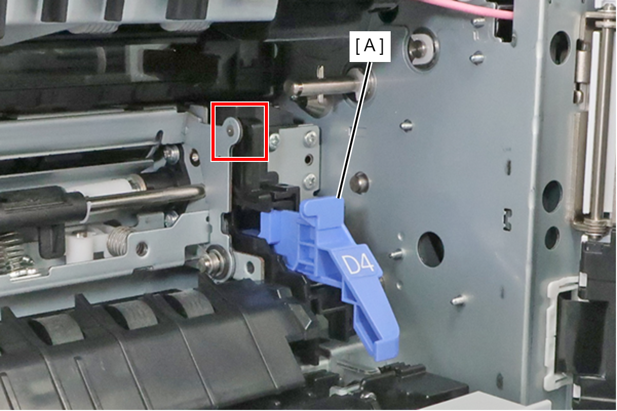
- Remove the dowel, and remove the Guide PF Inner Lever Assy (A).
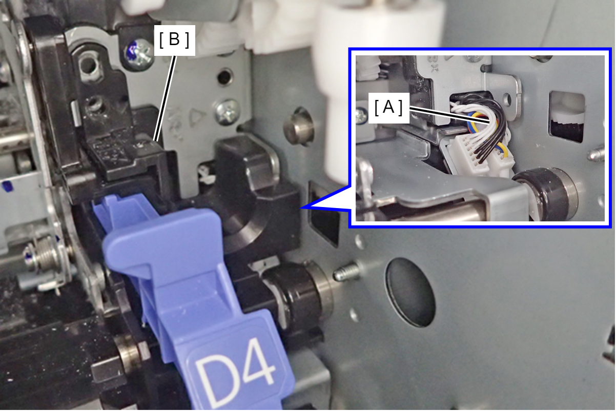
 Assembly / 組み立て
Be careful not to let the C1 Pickup Unit cable (A) get caught between components.
Before installing the Guide PF Inner Lever Assy (B), be sure to put protruding cables into the C1 Pickup Unit.
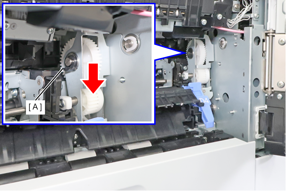
- Pinch the tab and pull it in the direction of the arrow to remove the C-ring (A).
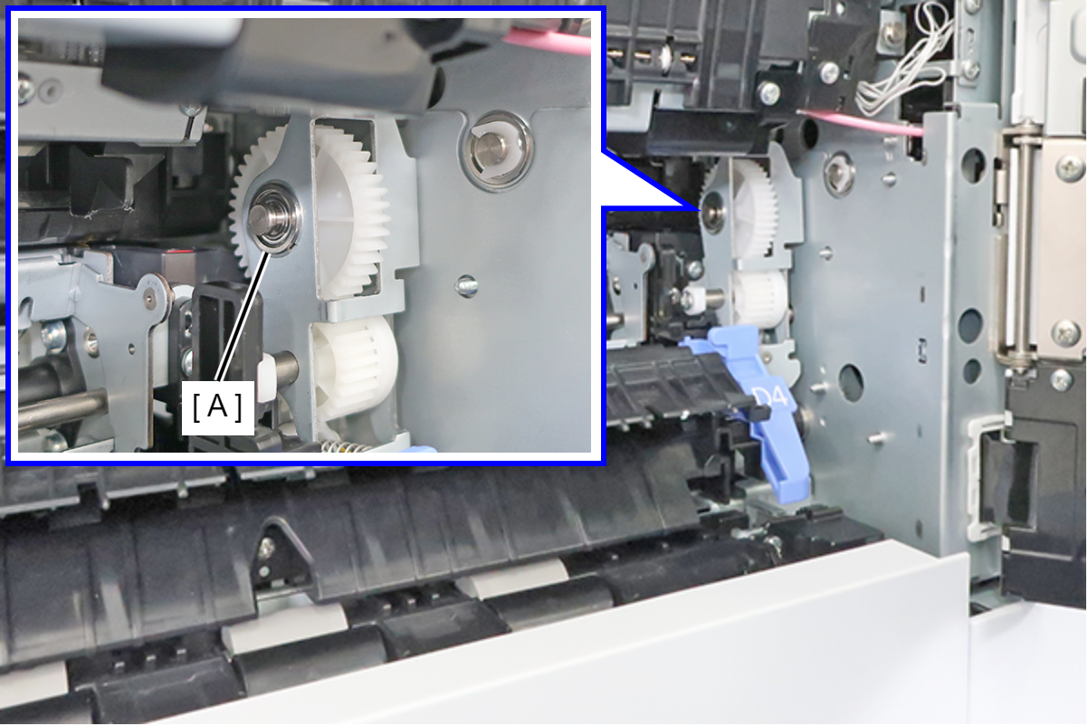
- Remove the bearing (A).
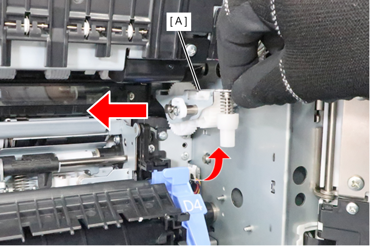
- Remove the Tumbler (A) in the direction of the arrow.
 Assembly / 組み立て
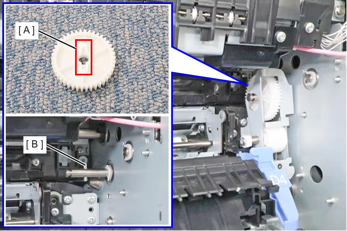
Align the pin (B) of the shaft with the groove (A) of the gear and install.
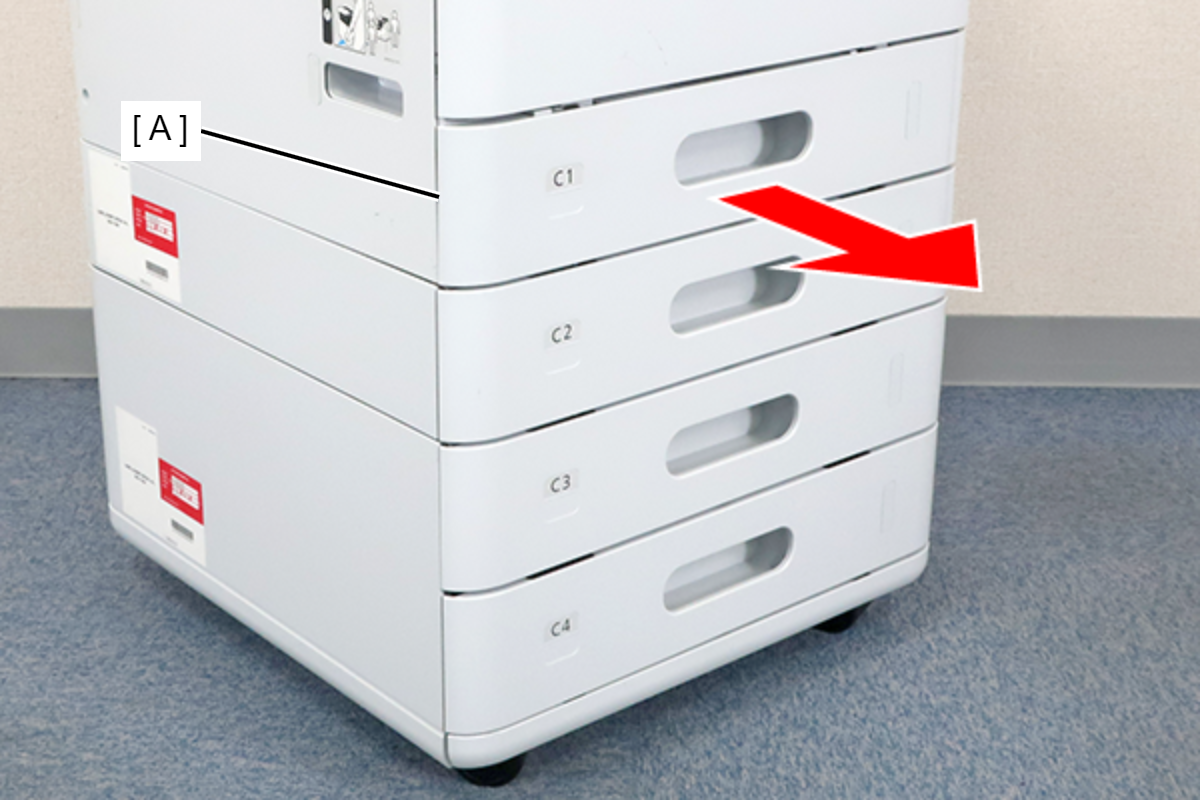
- Remove the C1 cassette (A).
- Remove the 3 screws and remove the Paper Guide Lower (A).
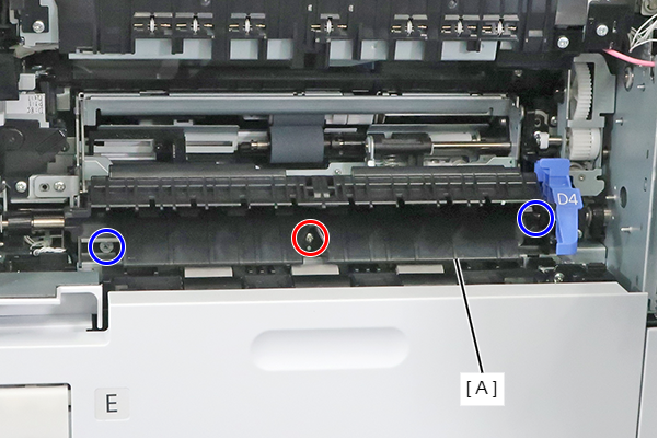
- : 3x8M
 : 3x5D
- Release the cable from the clamp (A) and disconnect the cable from the 2 relay connectors (B).
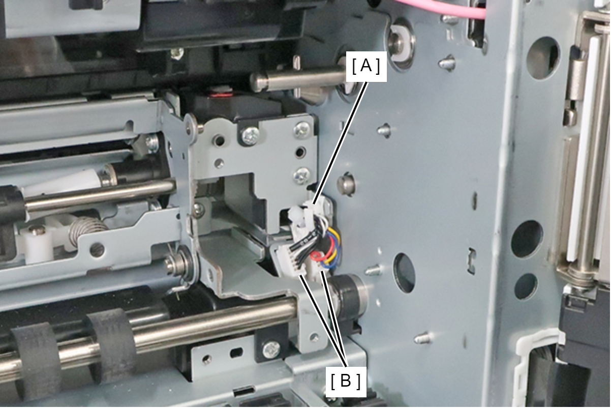 Assembly / 組み立て
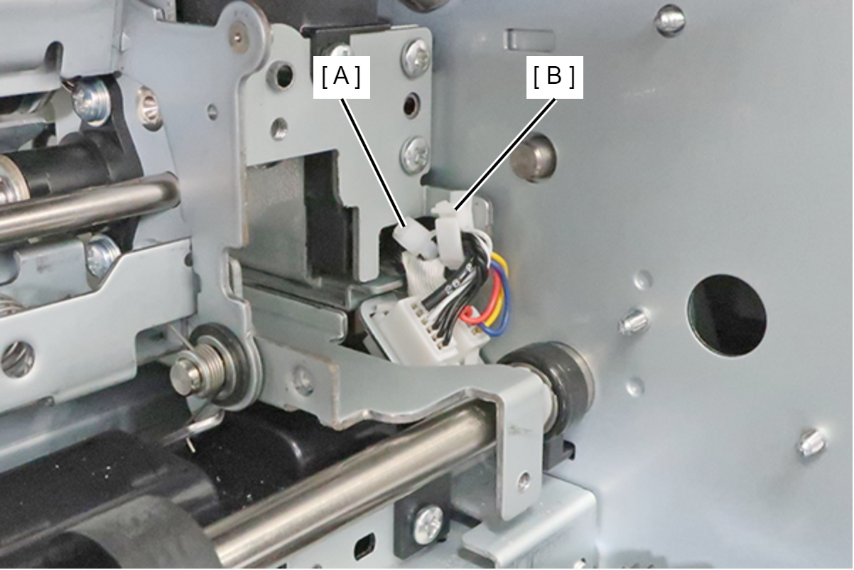
Attach the cable ties (A) so that it is disposed toward the back side of the clamp (B).
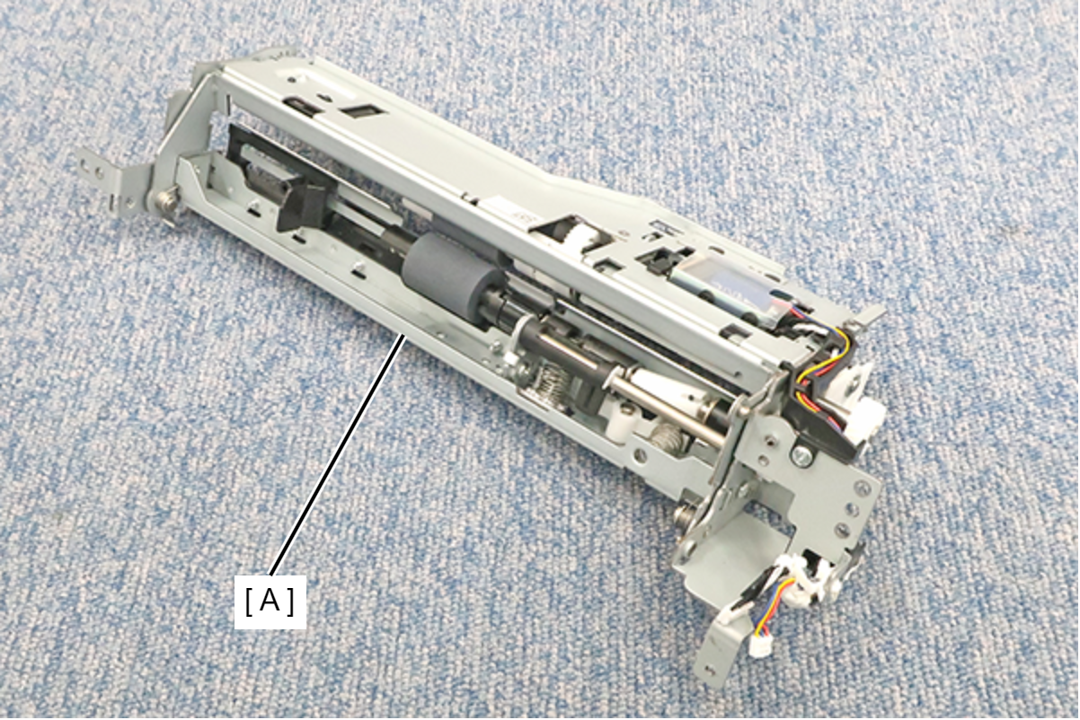
- Remove the 5 screws, and remove the C1 Pickup Unit (A).
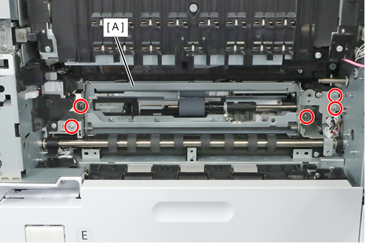
- : 3x8M
- Remove the 3 screws and remove the Right Cover (A).
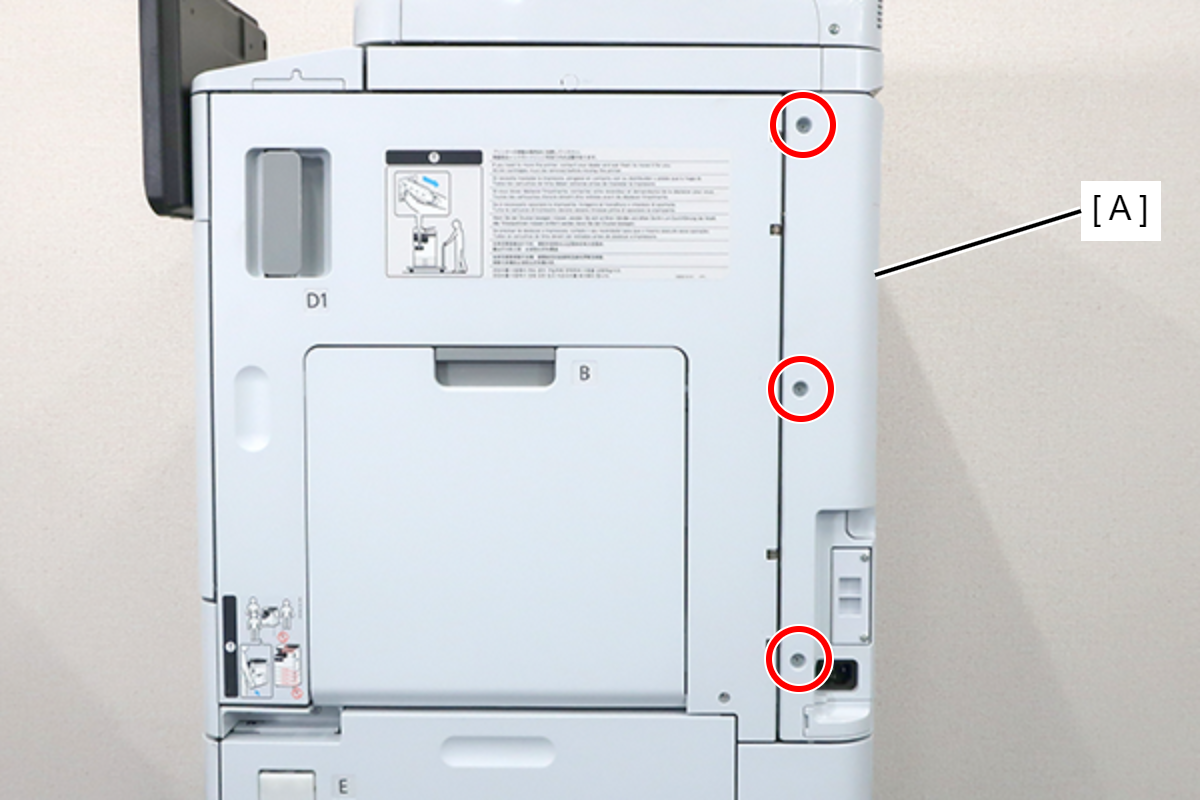
- : 3x8D
- Remove the 5 screws and pull the rear cover (A) toward to remove it.
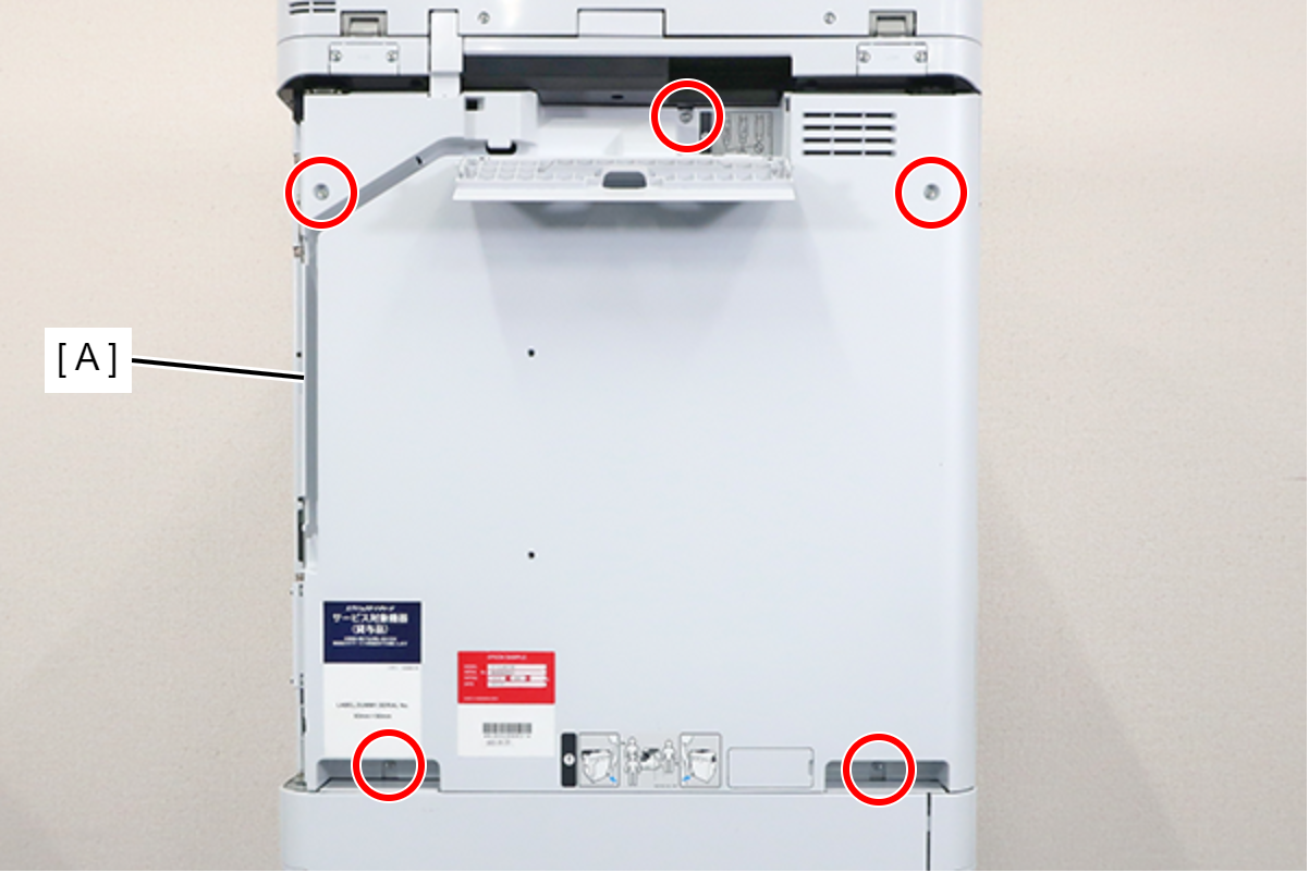
 : 3x8D
Assembly / 組み立てConfirm that the rear cover is not floating. The positioning pin (A) may not fit into the hole (B).
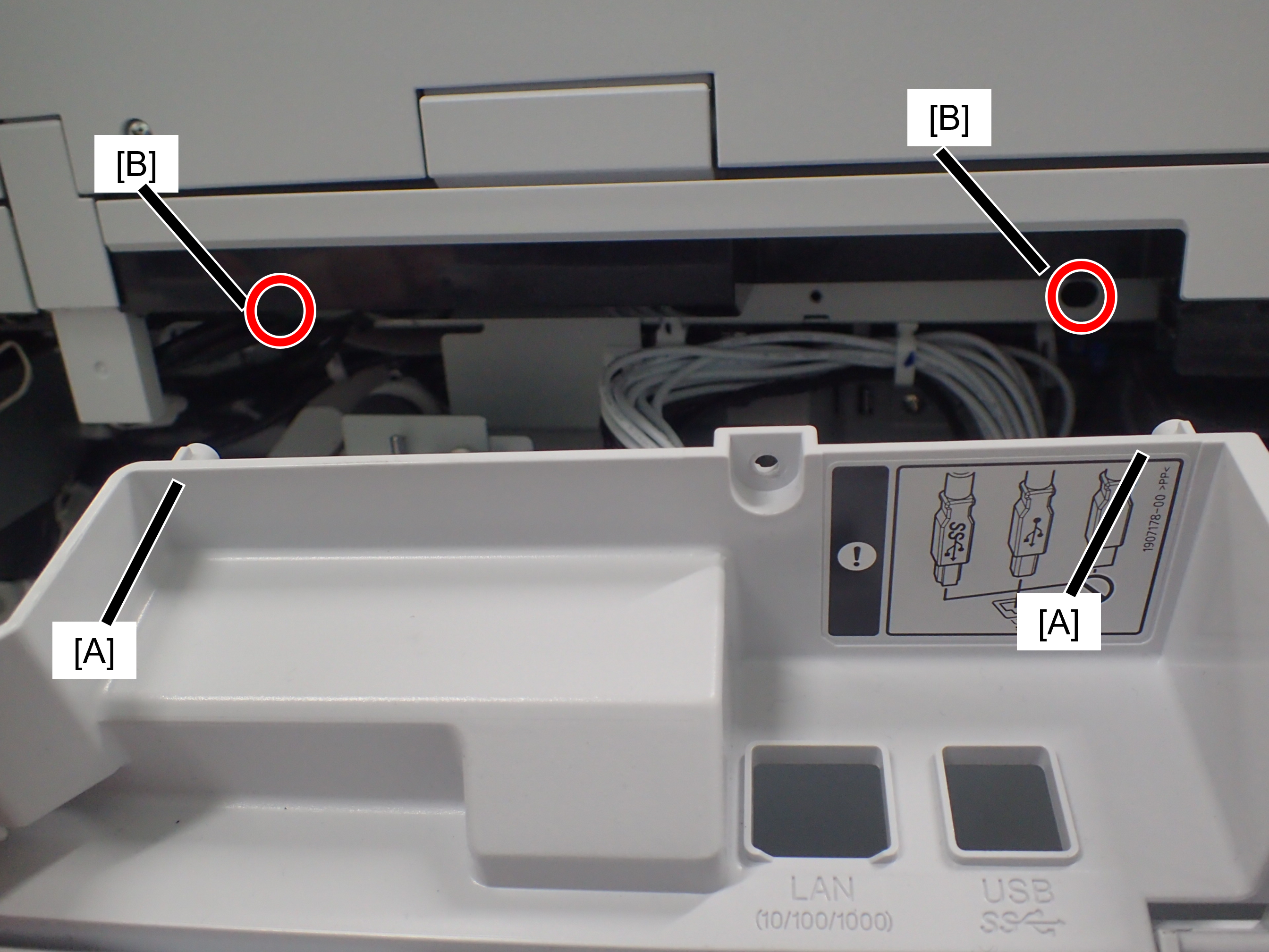
- Remove 3 screws and remove the I/F Slot Inlet Assy (A).
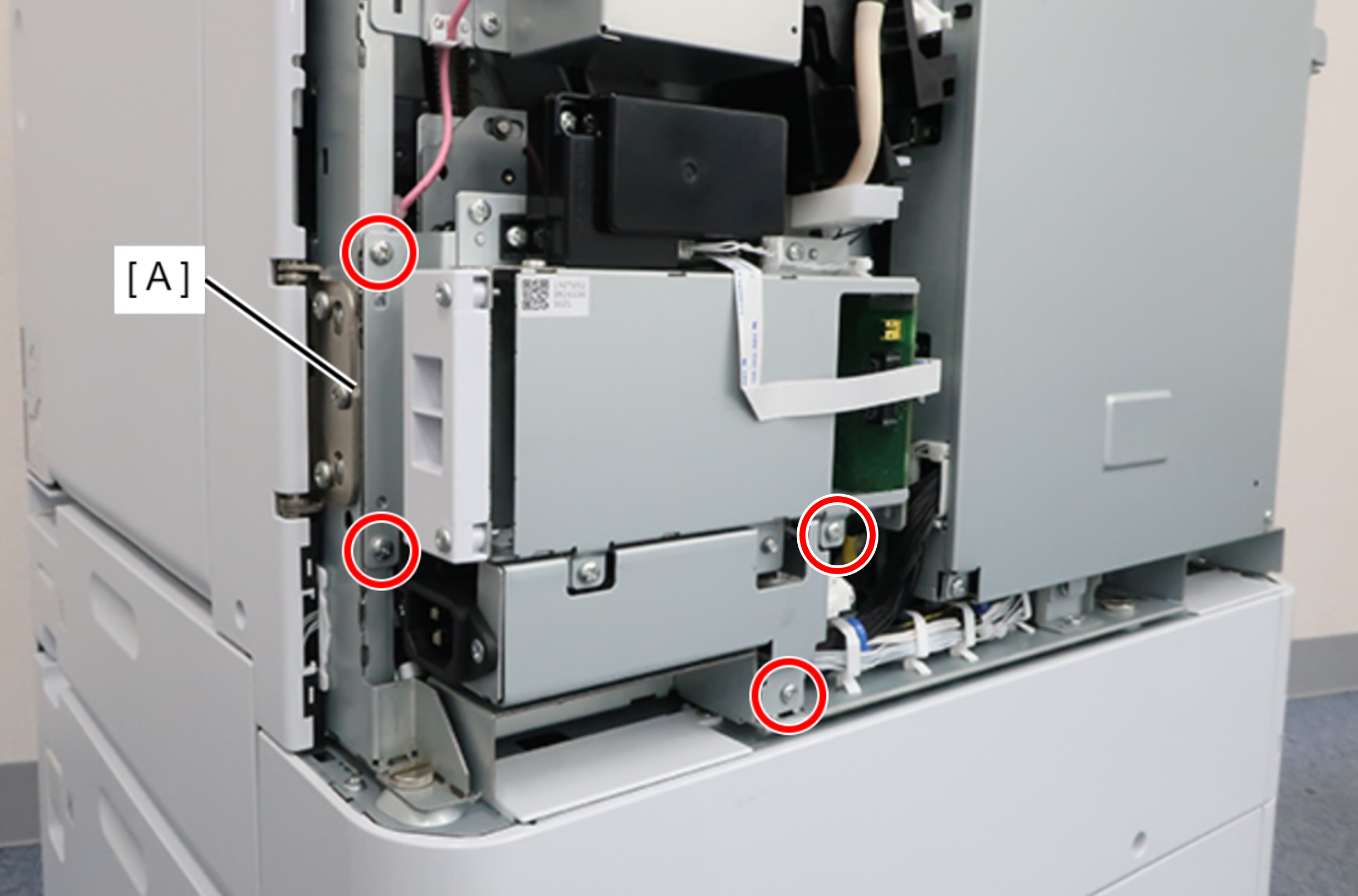
 : 3x8D
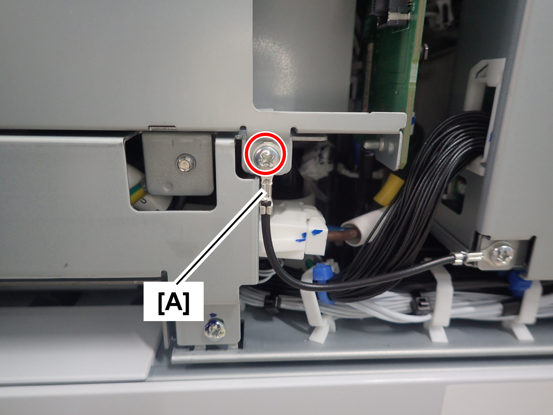
Assembly / 組み立てThe screw shown in the figure must be fastened together with the ground wire (A).
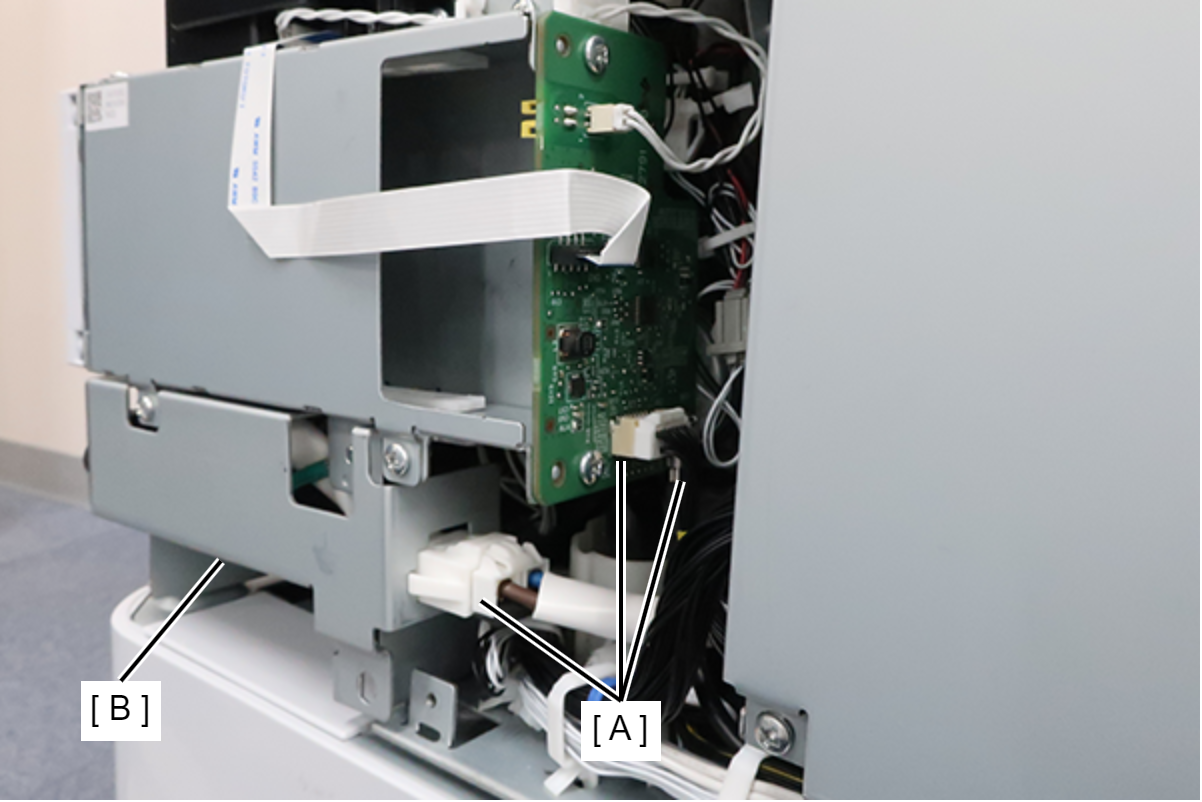
- Remove the cable from the connector (A) and remove the I/F Slot Inlet Assy (B).
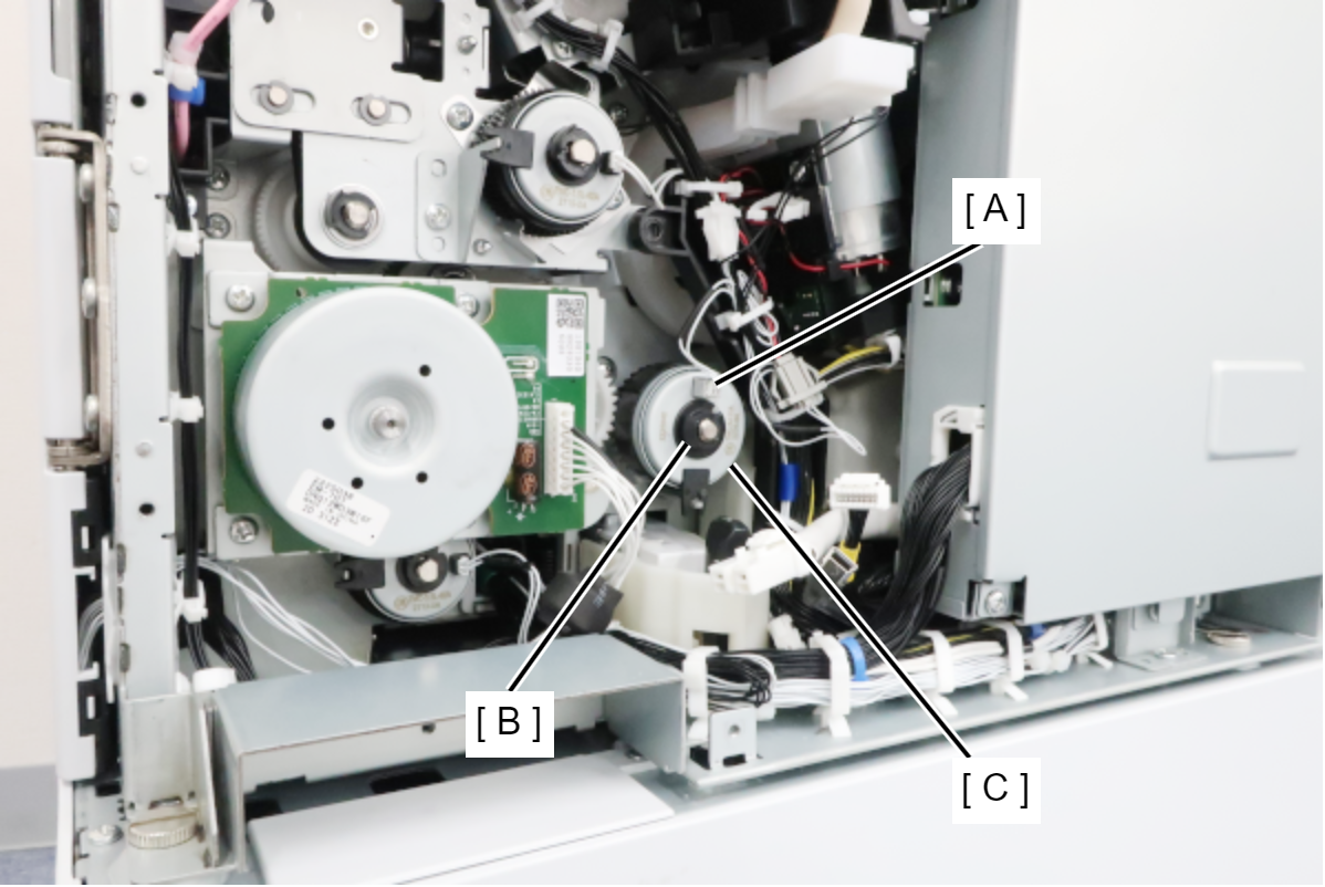
- Remove the cable from the connector (A), remove the C-ring (B), and the C1 Pickup Clutch (C).
- Remove the cable from the connector (A), remove the 3 screws, and remove the PF Motor Plate (B).
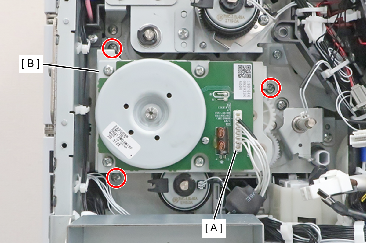
 : 3x8D
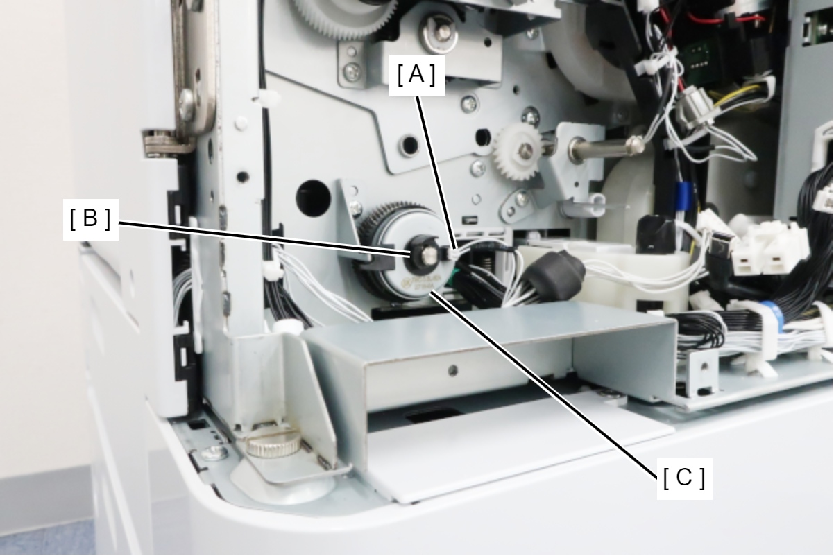
- Remove the cable from the connector (A), remove the C-ring (B), and remove the paper feed clutch (C).
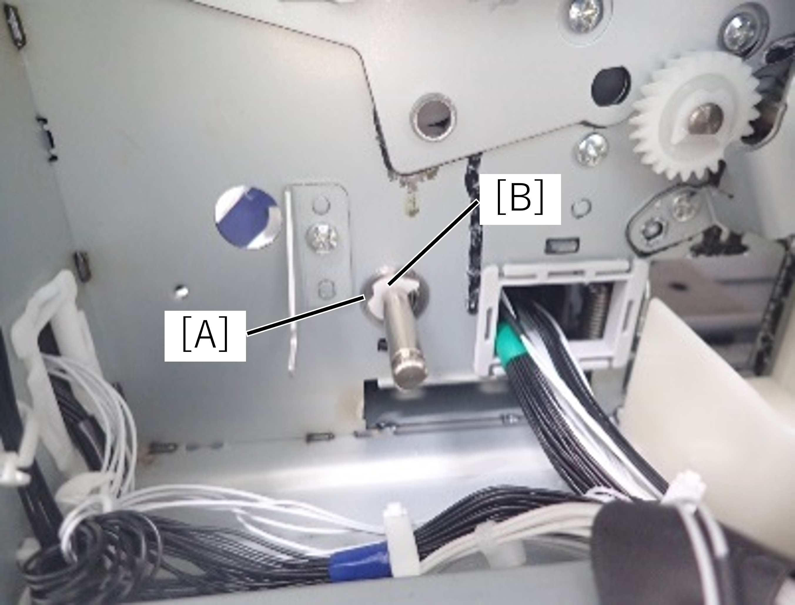
- Remove the paper feed roller retaining ring (A) and bearing (B) on the rear side of the main unit.
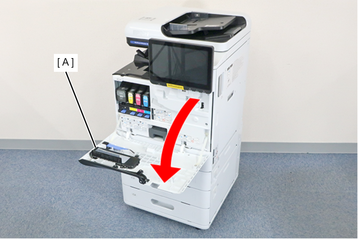
- Open the Front Cover (A).
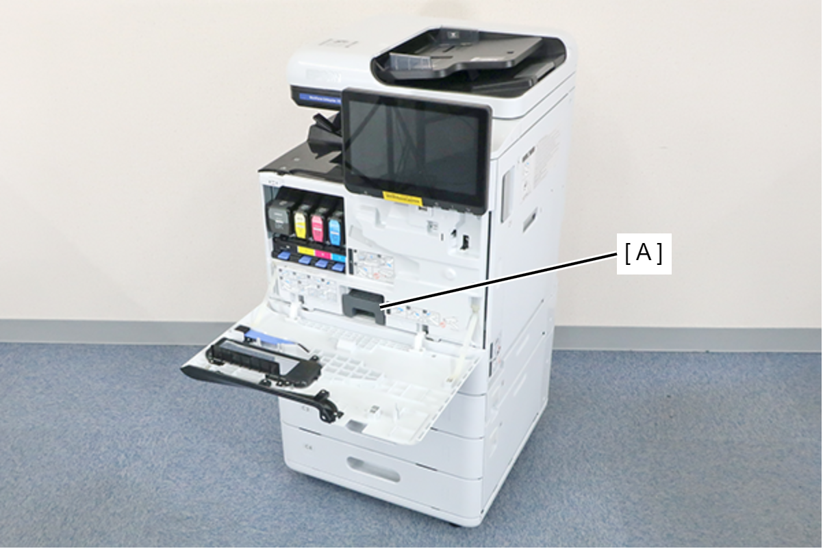
- Remove the Maintenance Box (A).
- Remove the 7 screws and remove the Front Inner Cover (A).
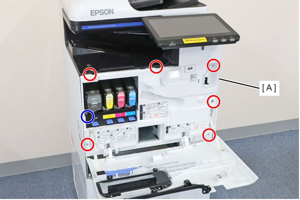
- : 3x8D
- : 3x8D/BK
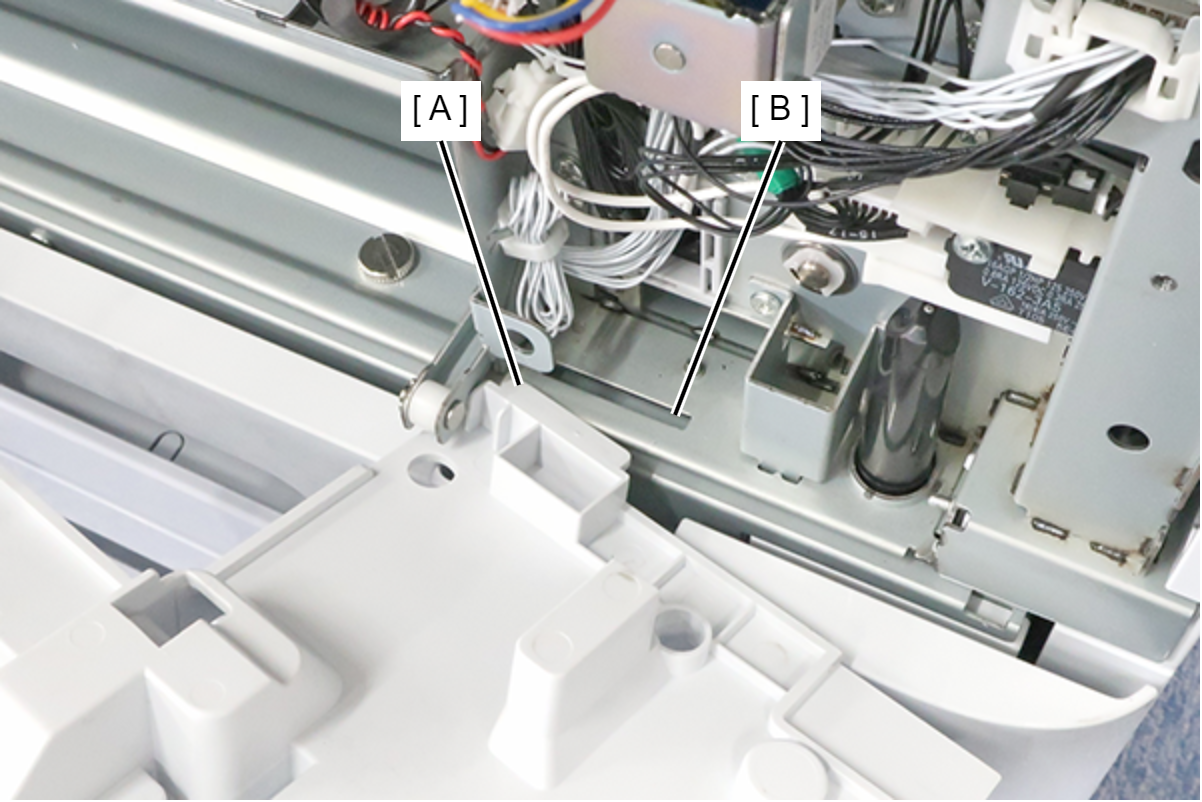
Assembly / 組み立てInsert the protrusion (A) of the Front Inner Cover into the hole (B) of the main unit and install.
 Note / 補足
If the wireless LAN unit (A) is installed, remove it.

- Remove the paper feed roller retaining ring (A) and bearing (B) on the front side of the main unit.
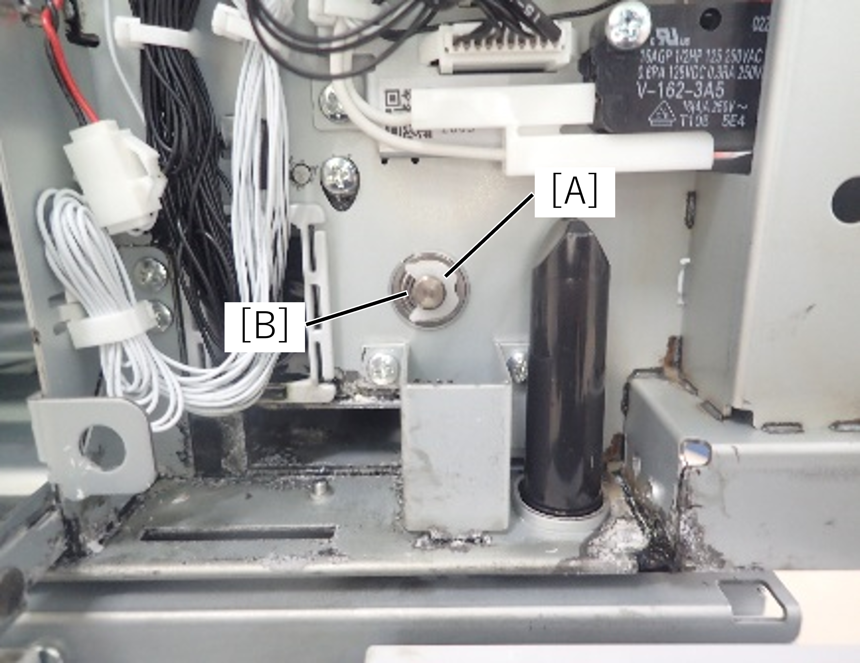
- Remove the retaining ring (A) of the paper feed roller inside the main unit.
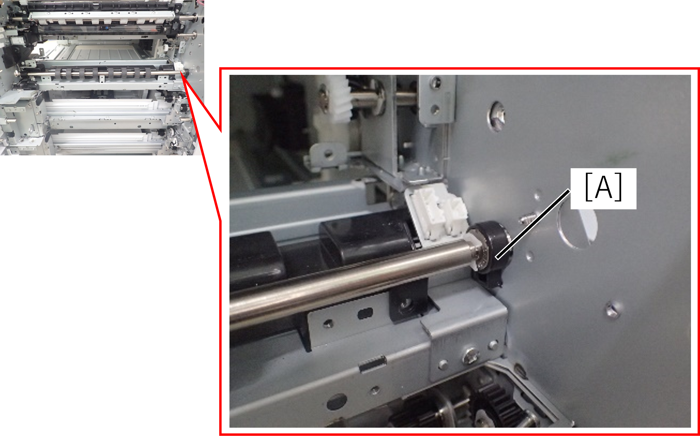
- Move the paper feed roller (A) to the rear side of the main unit.
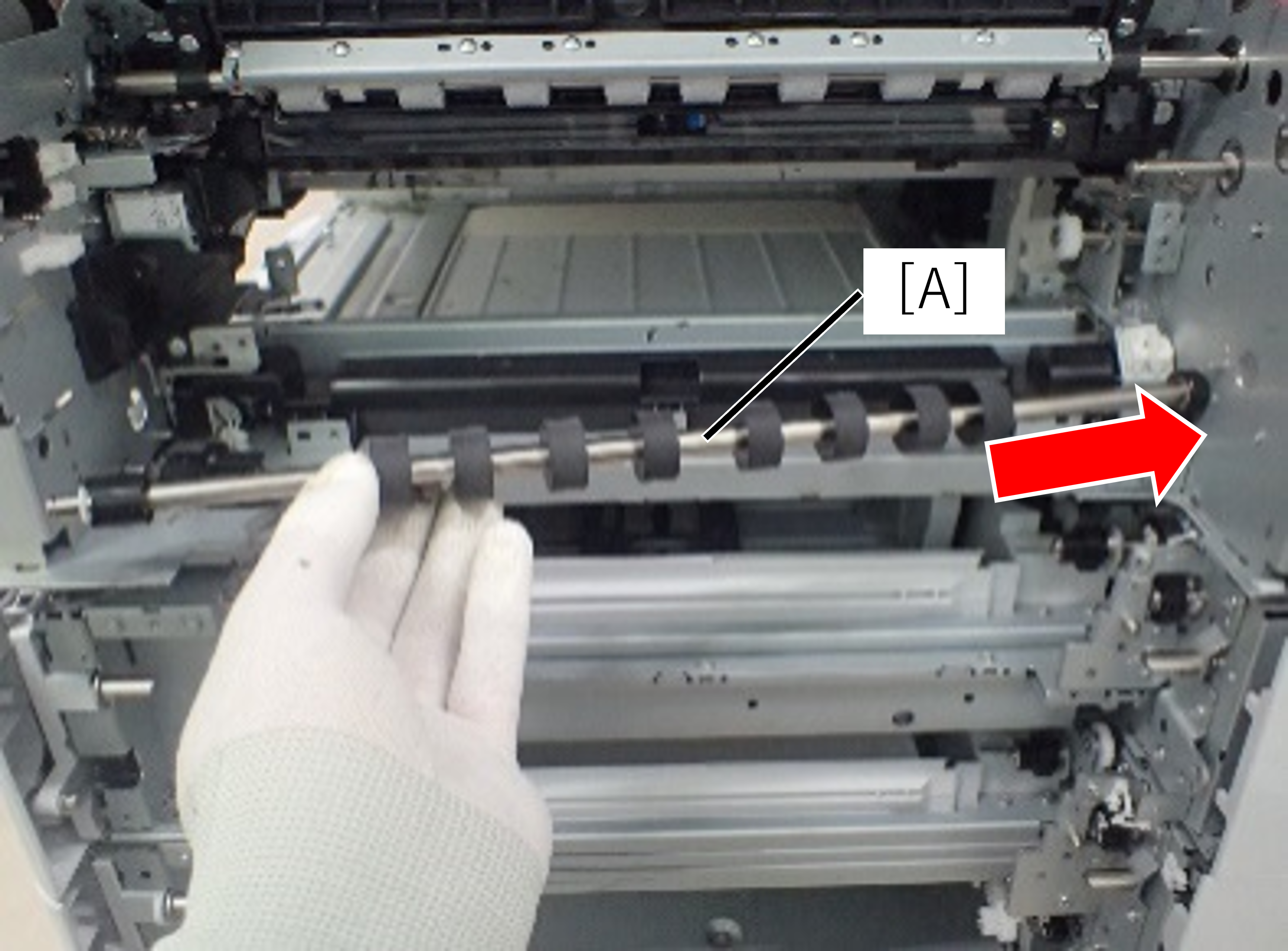
- Remove the paper feed roller (A) from the front side of the main unit.
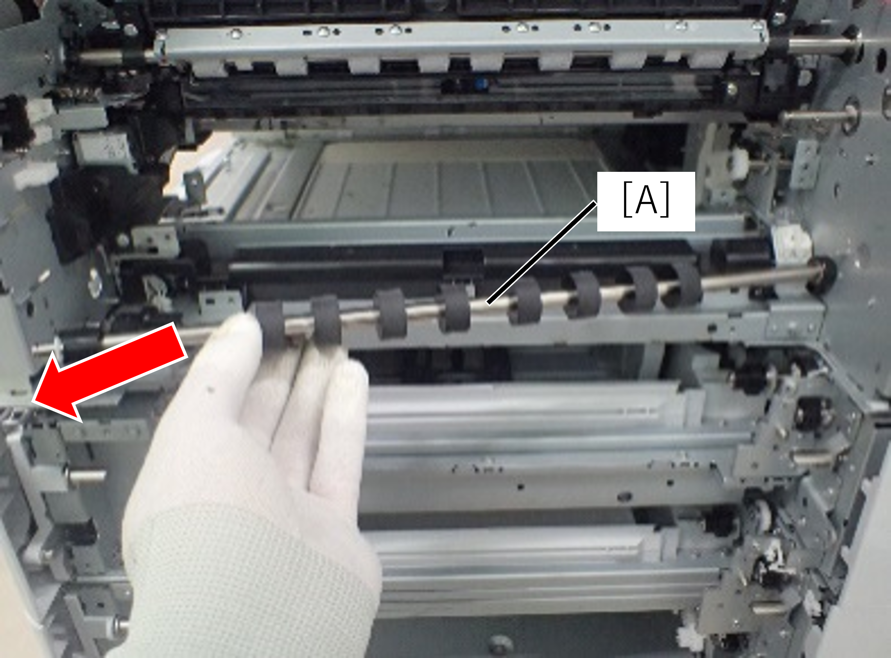
- Remove the retaining ring (A) and remove the torque limiter (B).
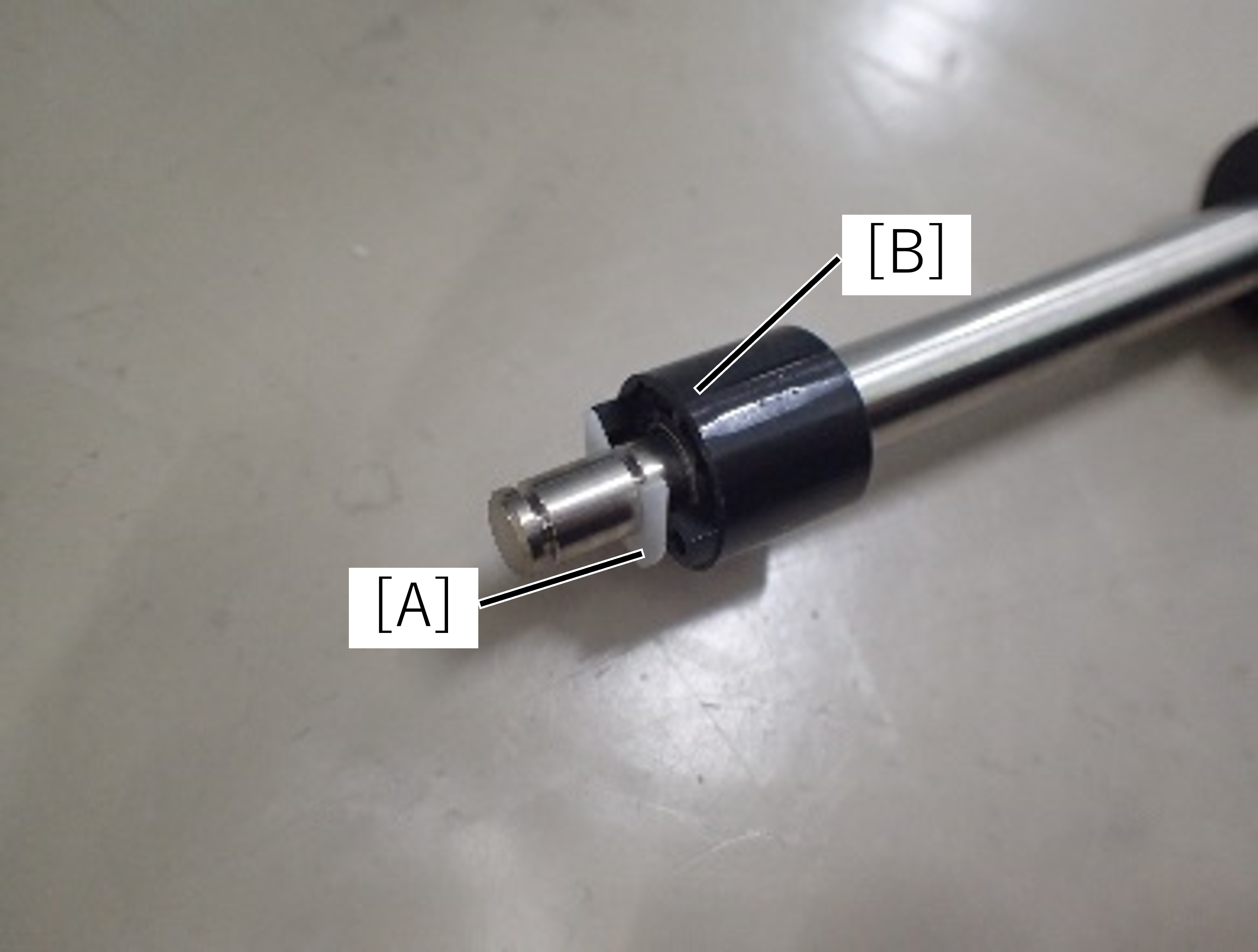
| Check Point / チェックポイント |
After replacing this part, you need to run the menu from the service support mode. (If you ran the Before-replacement menu before replacing the part, it will start automatically when you turn the power on.) |