
Inter-Lock Switch
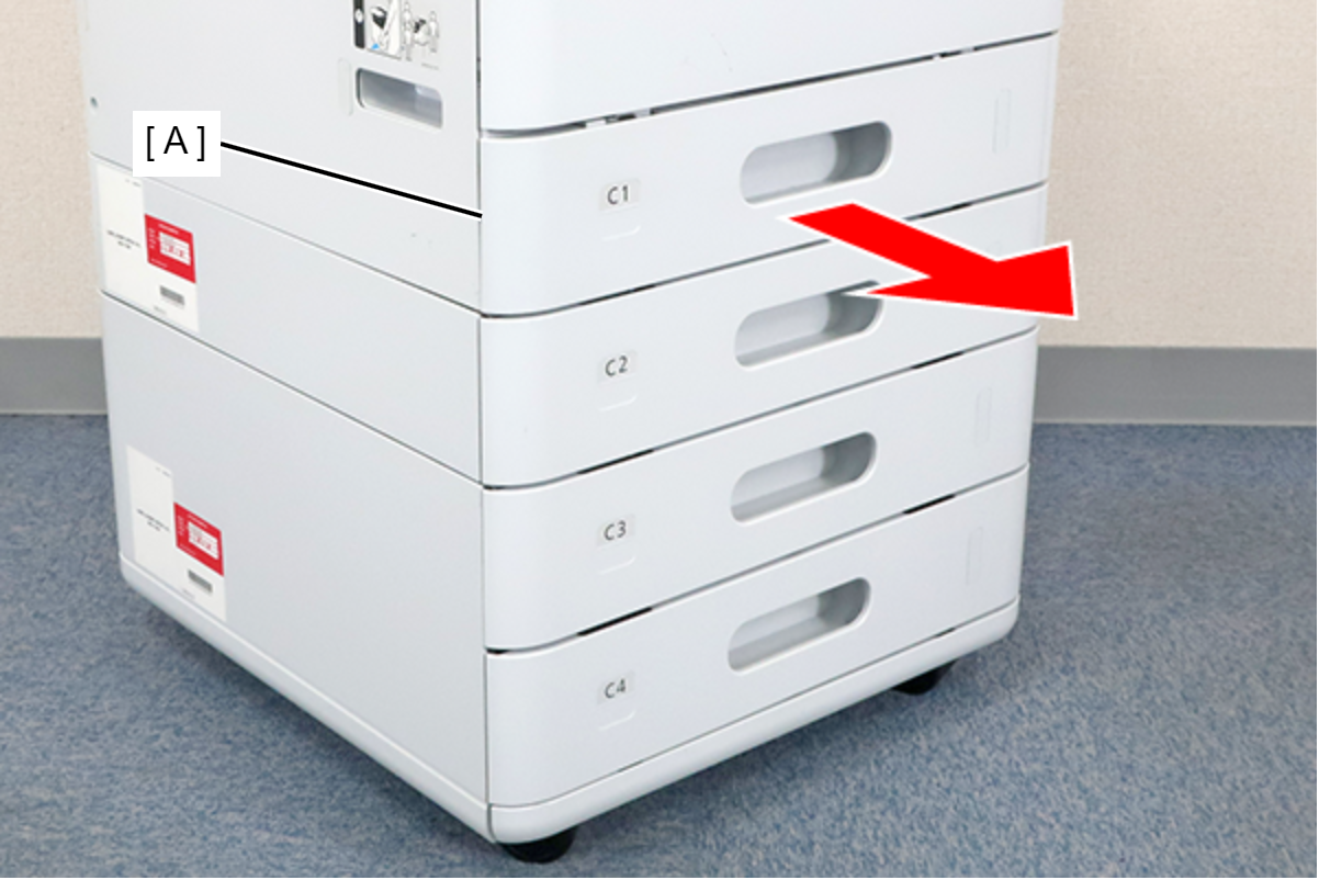
- Remove the C1 cassette (A).
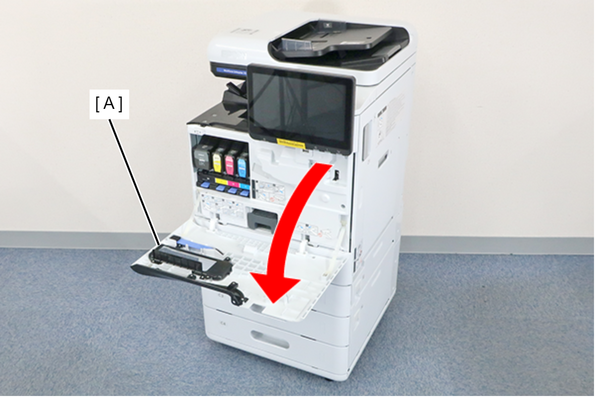
- Open the Front Cover (A).
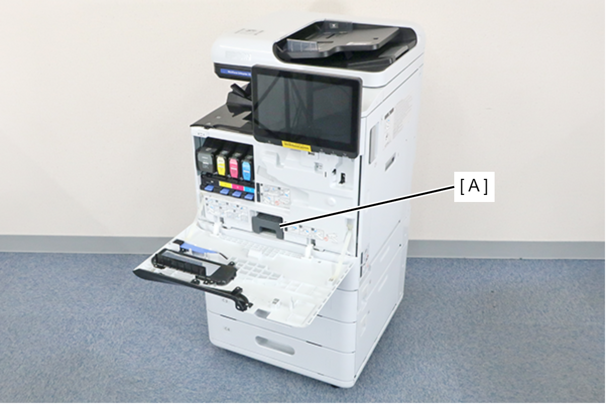
- Remove the Maintenance Box (A).
- Remove the 7 screws and remove the Front Inner Cover (A).
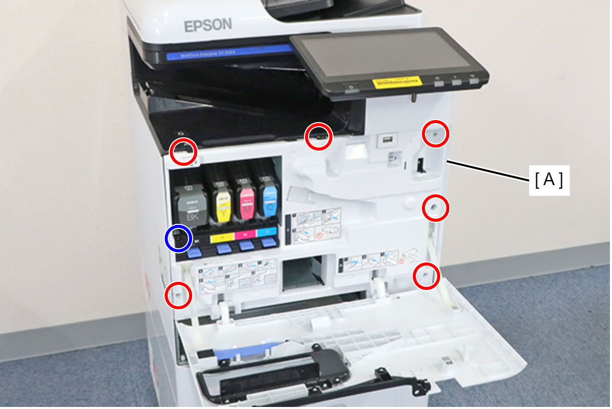
 : 3x8D
 : 3x8D/BK
 Assembly / 組み立て
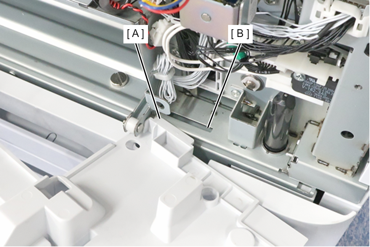
Insert the protrusion (A) of the Front Inner Cover into the hole (B) of the main unit and install.
 Note / 補足
If the wireless LAN unit (A) is installed, remove it.

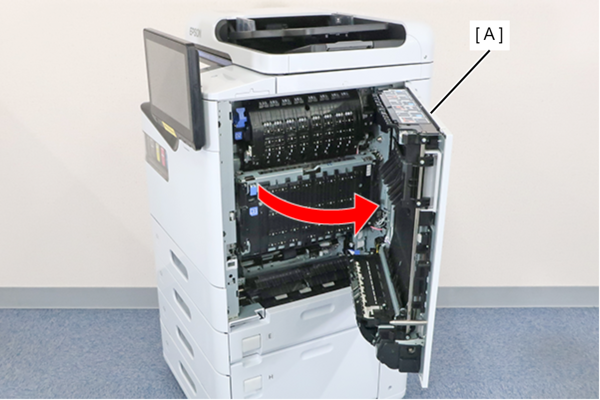
- Open the right door unit (A).
 Assembly / 組み立て
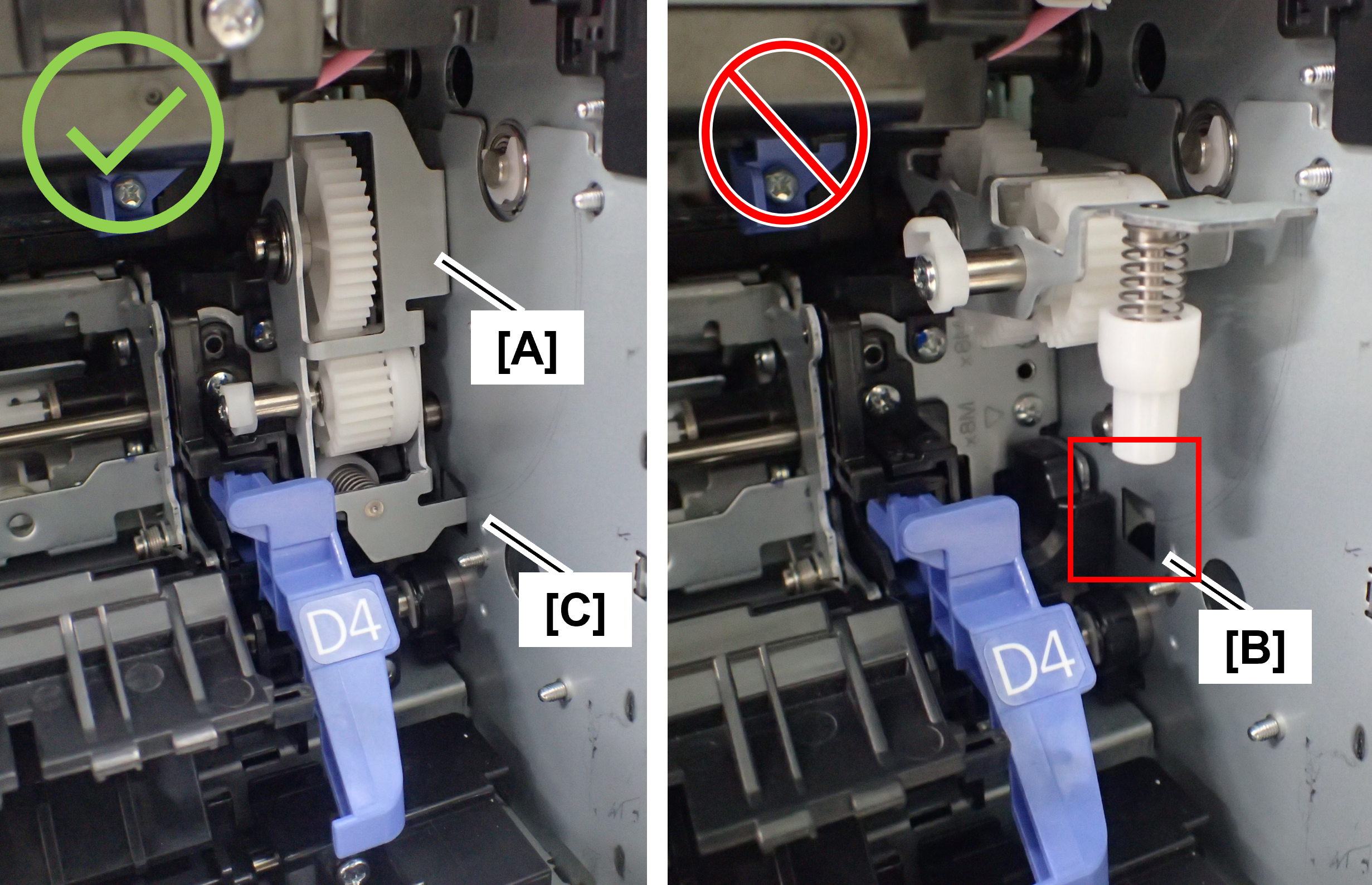
When closing the right door unit, it may not close due to interference with the tumbler (A) that was tilted toward the front when other parts were repaired.
If the right door unit does not close, check the position of the tumbler, and if it is protruding toward the front, fit the tip of the tumbler plate (C) into the hole (B) in the main unit.
- Remove the screw and remove the Connector Cover PW (A).
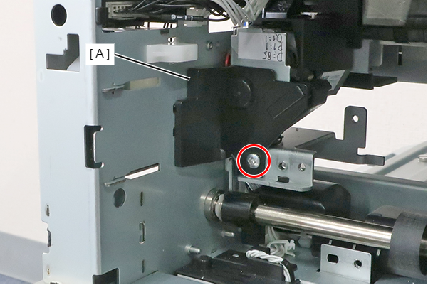
- : 3x8M
- Remove 1 screw and remove the Inter-Lock Switch (A) in the direction of the arrow.
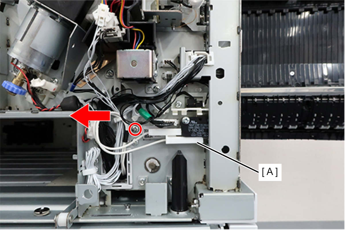
 : 3x6D
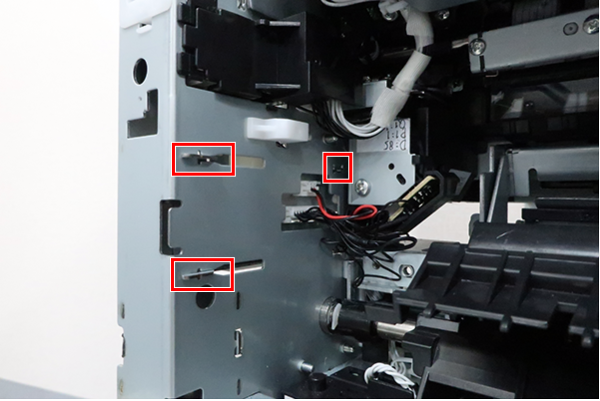
Assembly / 組み立てWhen installing the Right Door Inter-lock Assy, align the 3 hooks with the notches on the main unit side.
- Remove cable (A), remove 2 screws, then remove the Inter-Lock Switch (B).
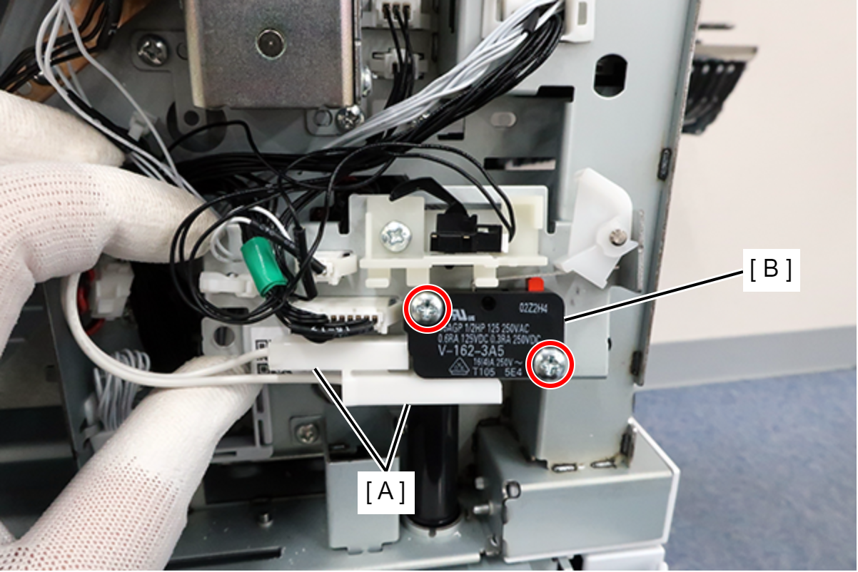
- : 3x15D