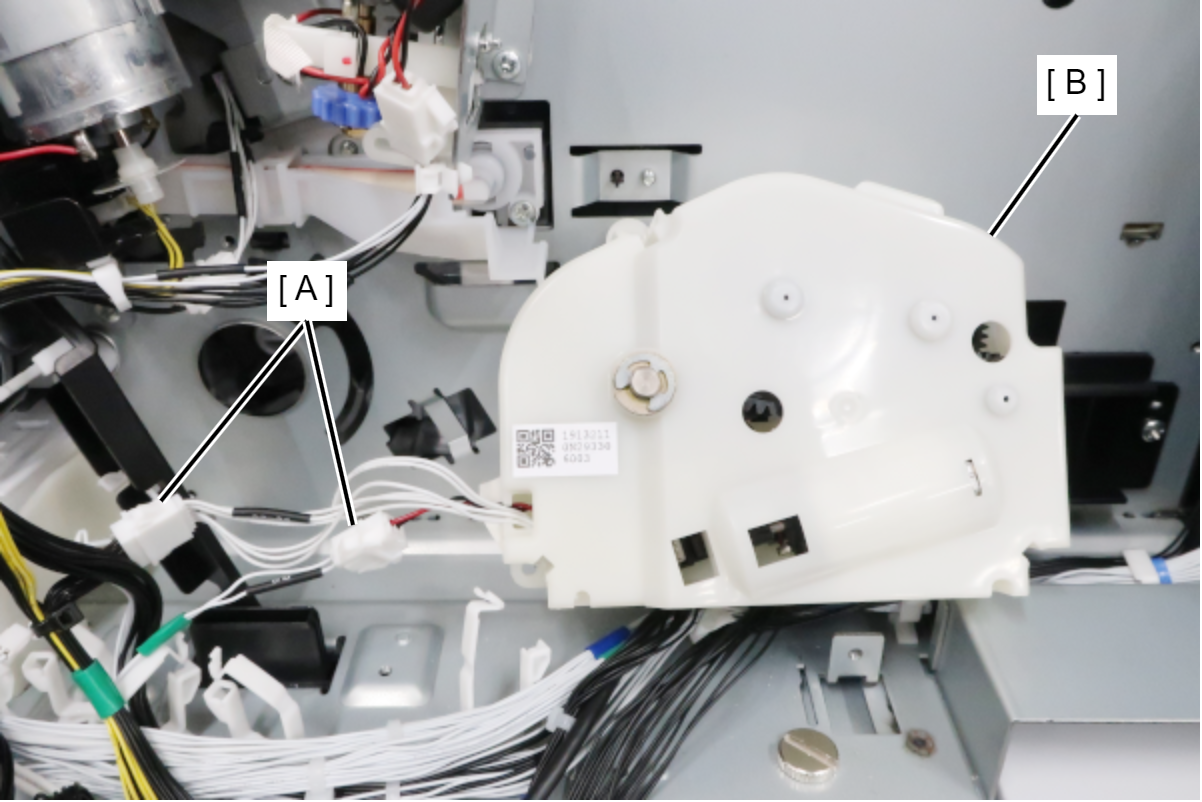
C1 Liftup Motor Assy
- Remove the 3 screws and remove the Right Cover (A).
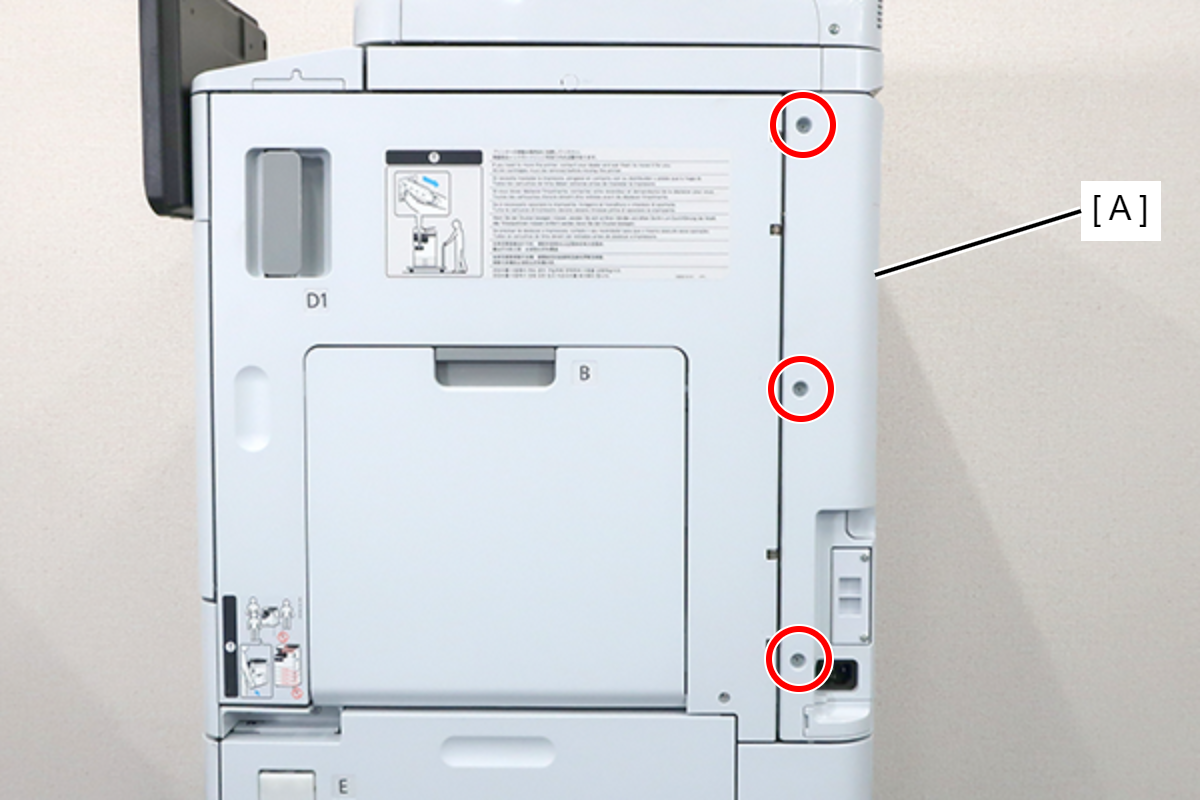
 : 3x8D
- Remove the 5 screws and pull the rear cover (A) toward to remove it.
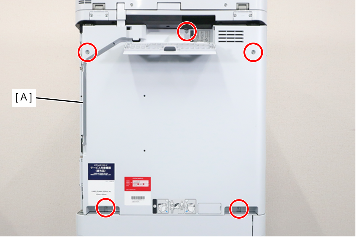
 : 3x8D
 Assembly / 組み立て
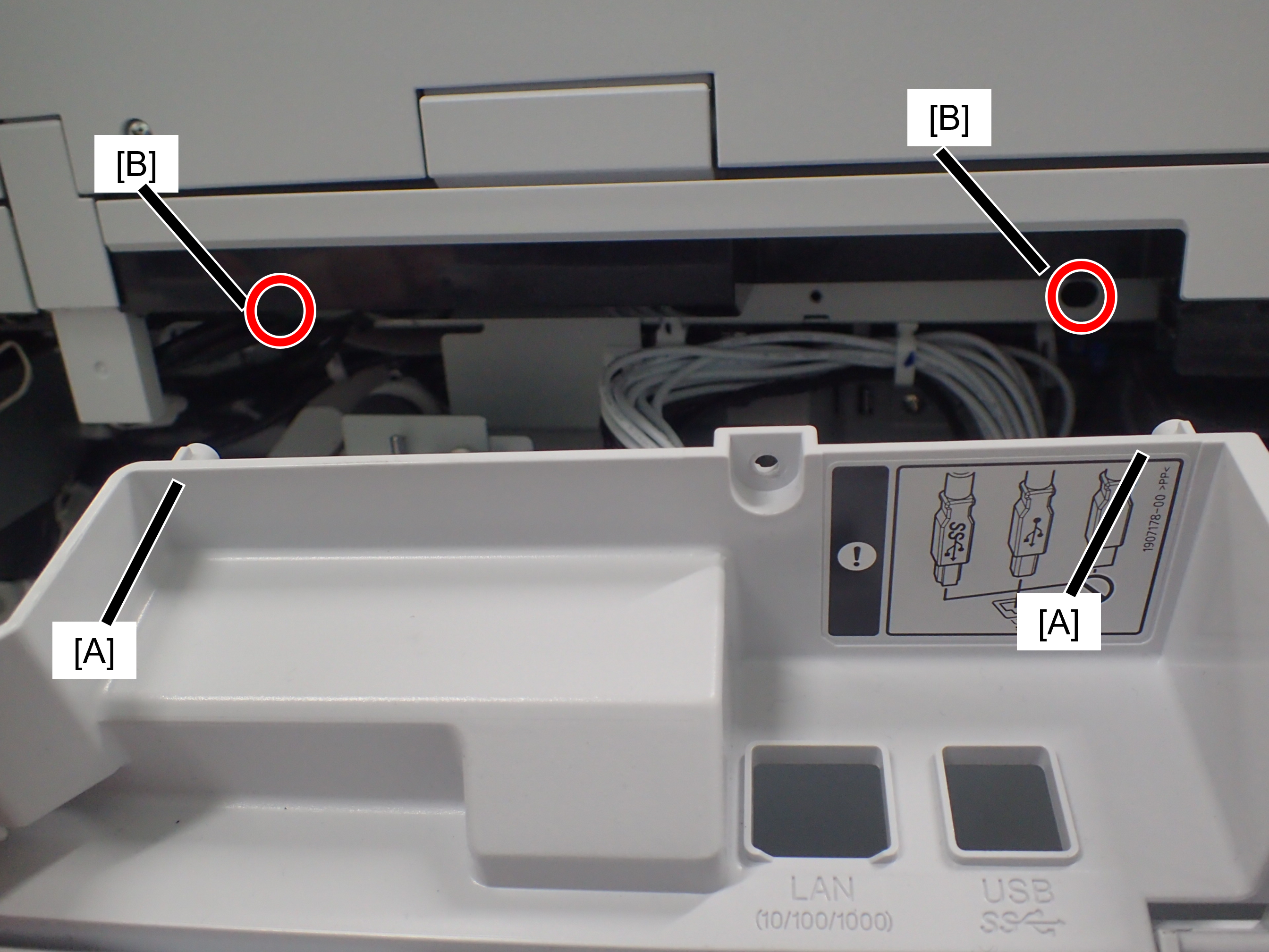
Confirm that the rear cover is not floating. The positioning pin (A) may not fit into the hole (B).
- Remove the 5 screws fixing the Main Board Cover (A).
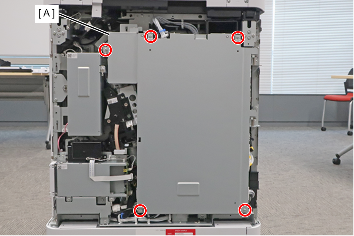
- : 3x8D
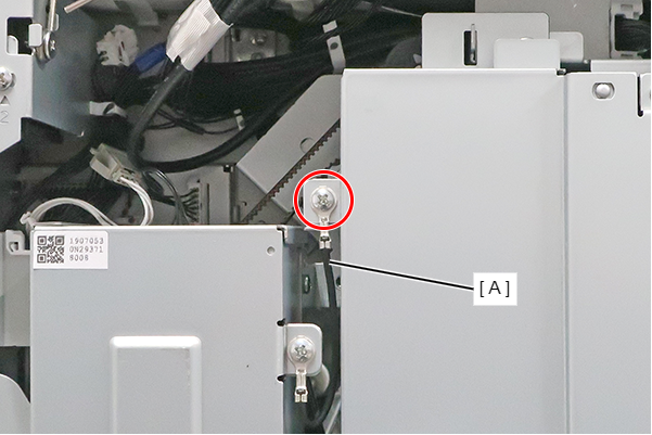
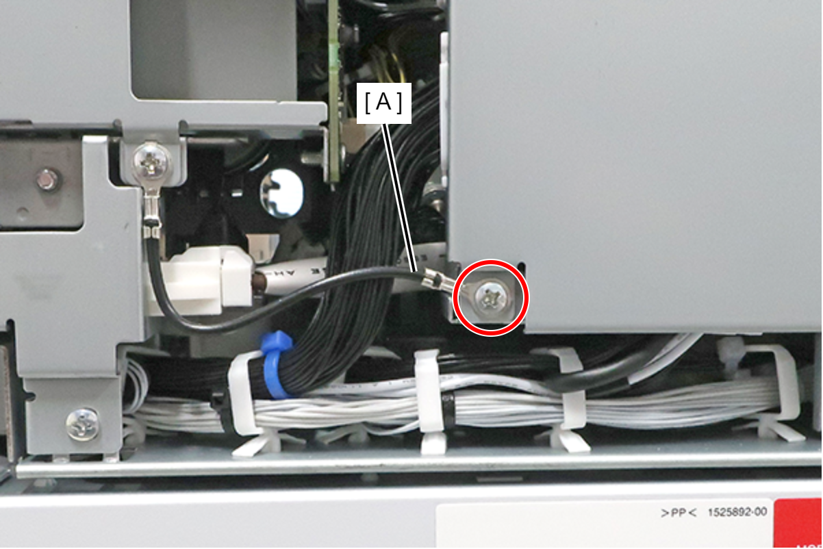
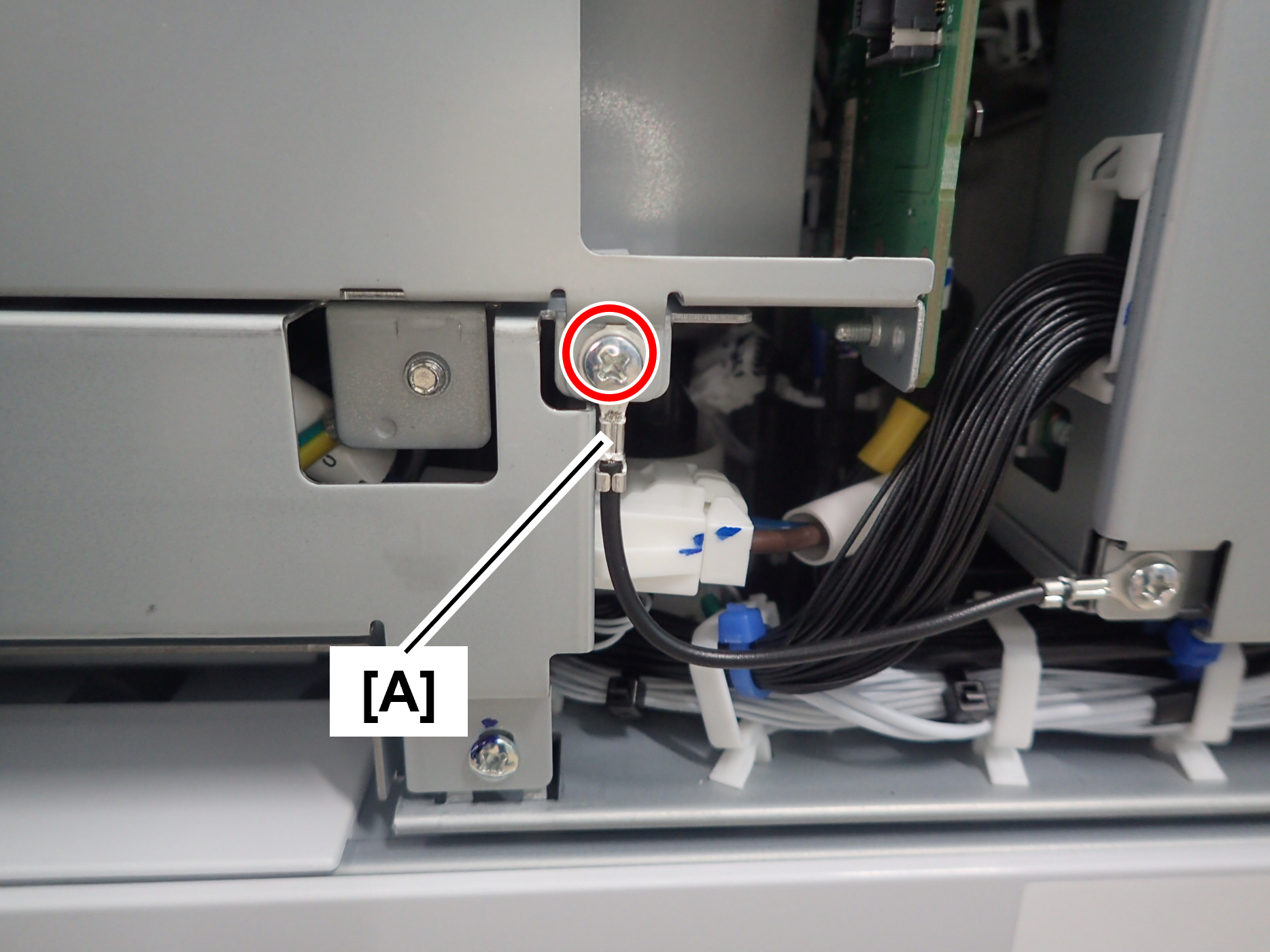
Assembly / 組み立てThe screw shown in the figure must be fastened together with the ground wire (A).
When installing the Main Board Cover, hold the center part with your hand while tightening the screws to prevent the cover from lifting.
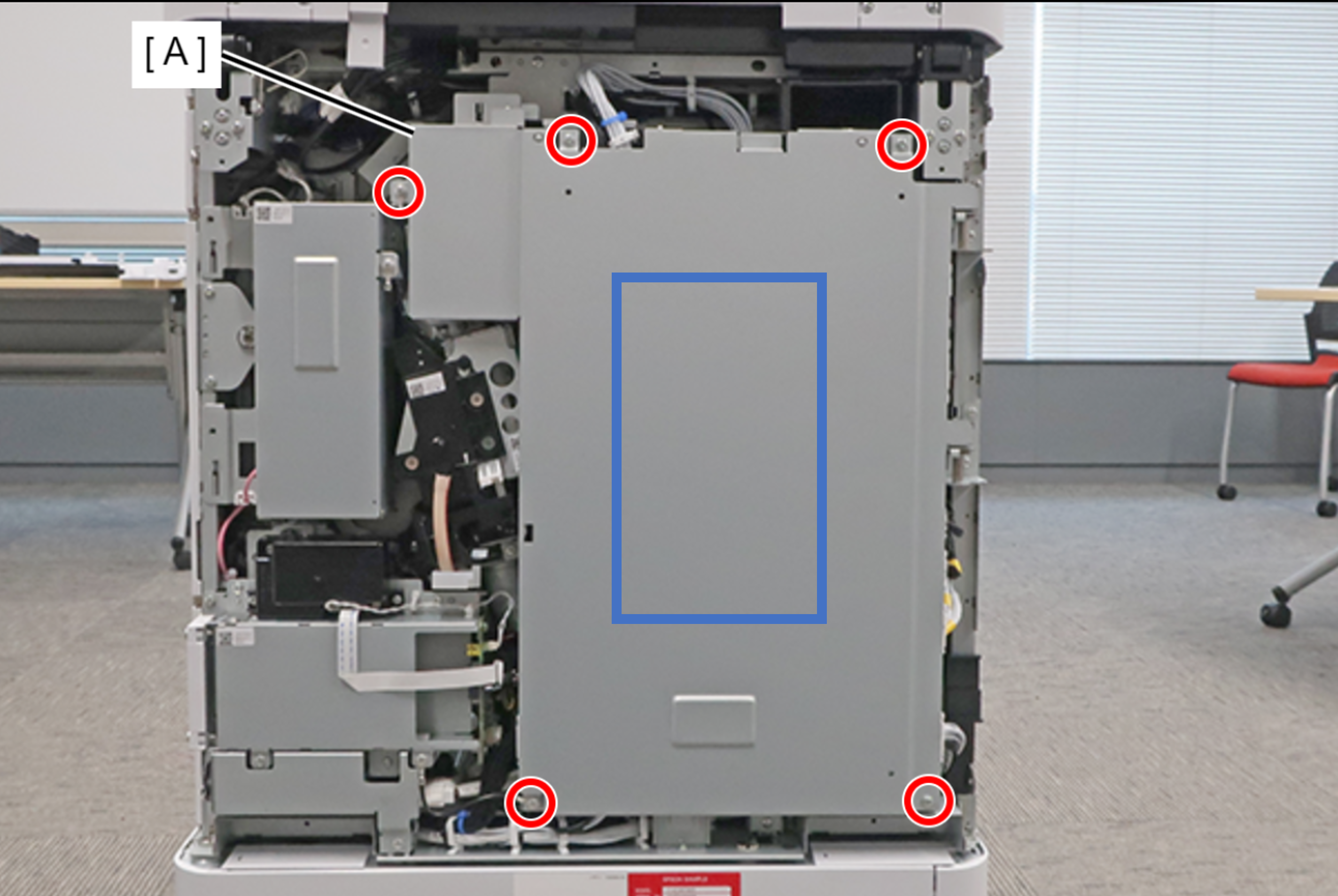
- Lift the main board cover (A) slightly to release the dowel (B) and open the main board cover (A).
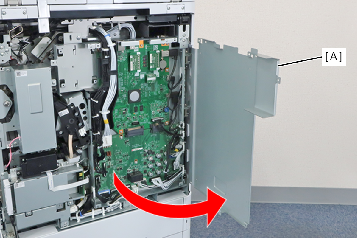
 Note / 補足
The Main Board Cover (A) can be completely removed by lifting it in the open position shown above.
- Disconnect the cables from the connectors (B) (CN3/CN4/CN6/CN13) of the MCU Board (A), and remove the screw. Remove the clamp (C).
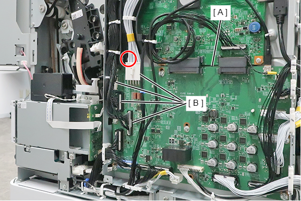
- : 3x8D
- Hang the protrusion of the MCU Wiring Rail (A) on the Wire Hook (B), and withdraw it.
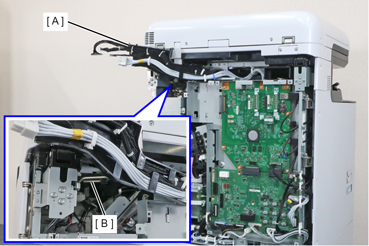 Assembly / 組み立て
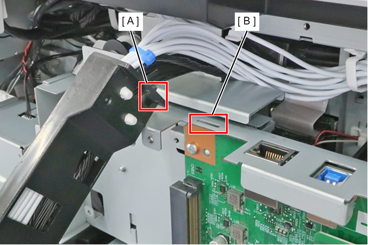
Engage the hook (A) of the MCU Wiring Rail in the hole (B) of the Board Box and install.
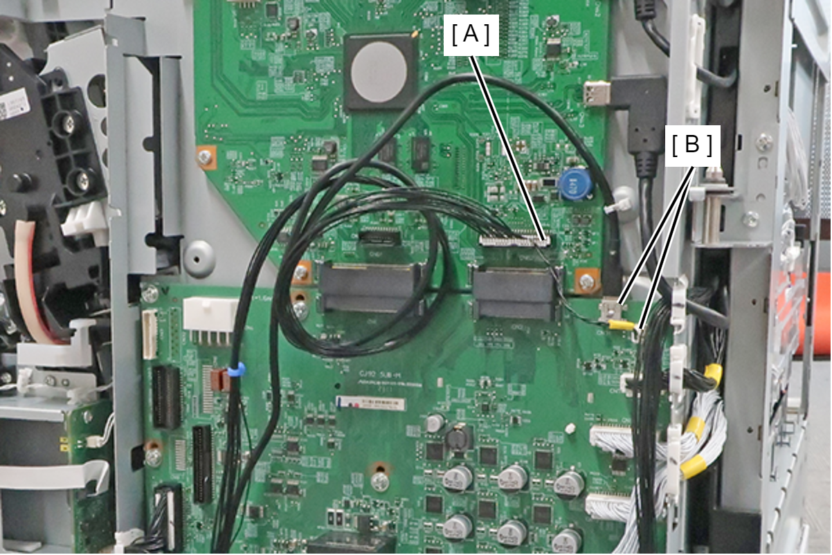
- Disconnect the cables from the main board connector (A), the MCU board connectors (B) and release from clamp (C).
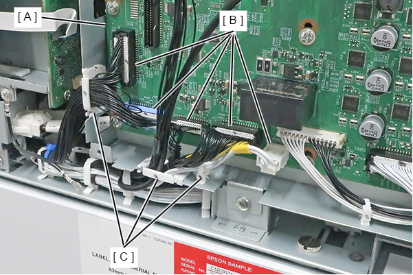
- Disconnect the cables (CN5/CN10/CN11/CN12/CN504) from the connector (B) of the MCU Board (A), and release the from the 3 clamps (C).
- Remove the 2 screws, slightly lift the board box (A) to release the hook.
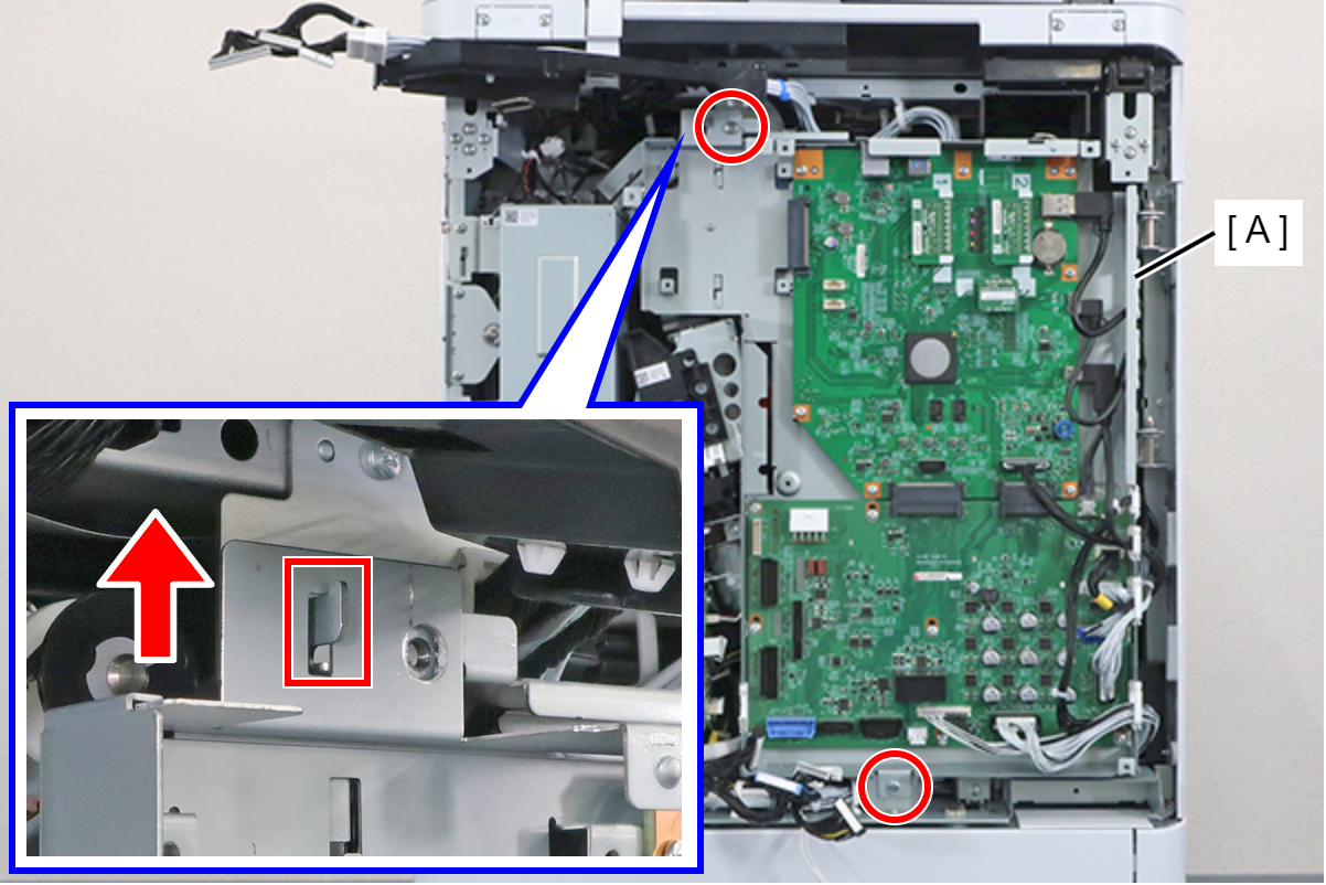
- : 4x8D
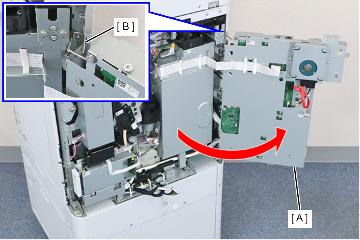
- Open the Board Box (A), and fix with the Wire Hook (B).
 Caution / 注意
Be careful not to close the Board Box with the Wire Hook fixed in place.
- Remove the screw and remove the Power Supply Box Support Frame (A).
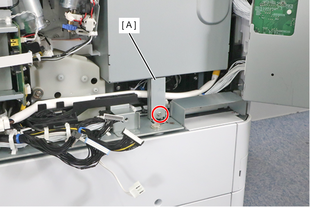
- : 3x8D
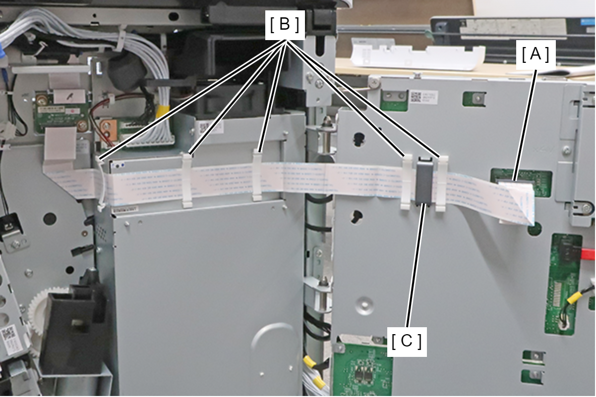
- After disconnecting the FFC from the connector on the main board, remove the 5 FFC clamps (B). Then, remove the panel relay FFC (A)
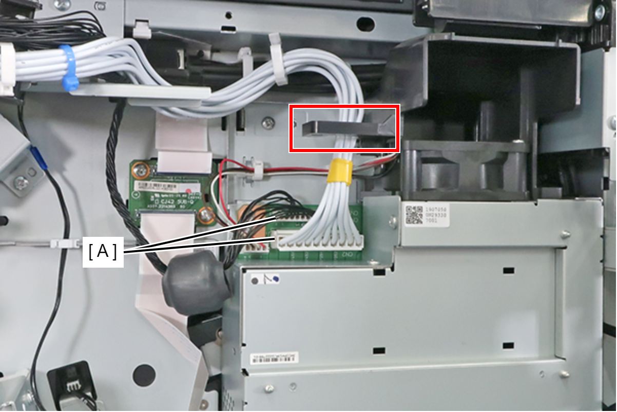
- Disconnect the cables from the 2 connectors (A) of the Power Supply Box, and disconnect the cables from the hook.
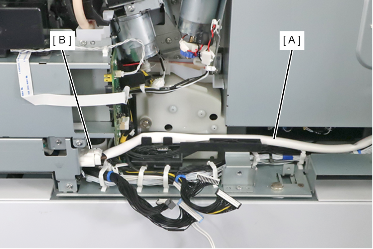
- Release the power cable (A) from the routing, and disconnect it from the connector (B).
- Remove the 3 screws fixing the Power Supply Box (A).
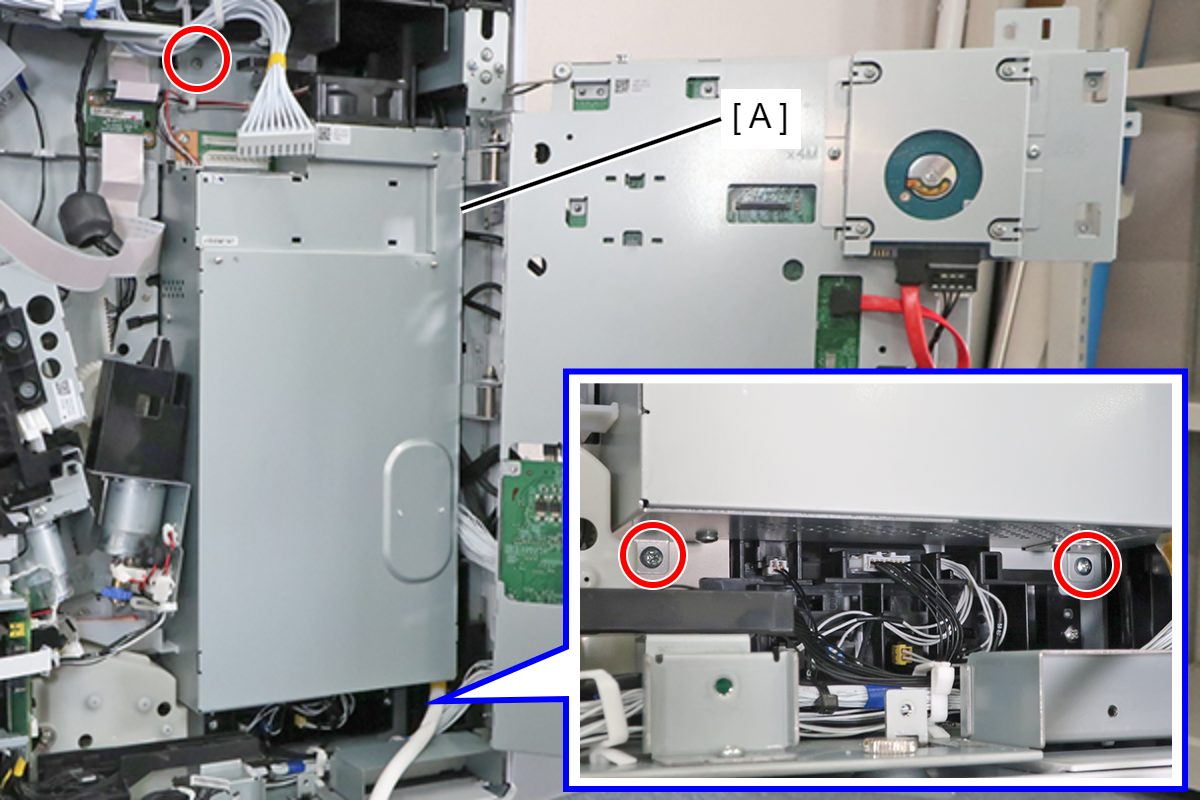
- : 3x8D
- Hold the lower side of the Power Supply Box (A) and lift it, then disengage it from the 2 hooks, and remove the Power Supply Box.
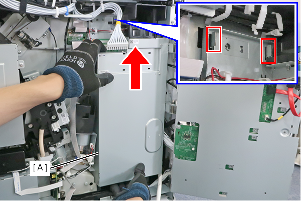 Assembly / 組み立て
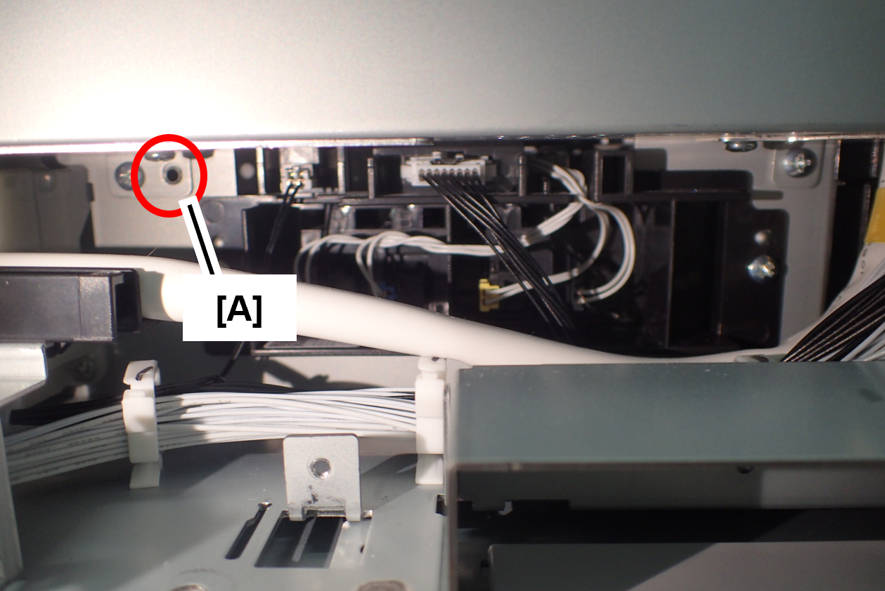
When installing, align it with the positioning hole (A).
Also, make sure the wiring is not pinched.
- Remove 3 screws and remove the I/F Slot Inlet Assy (A).
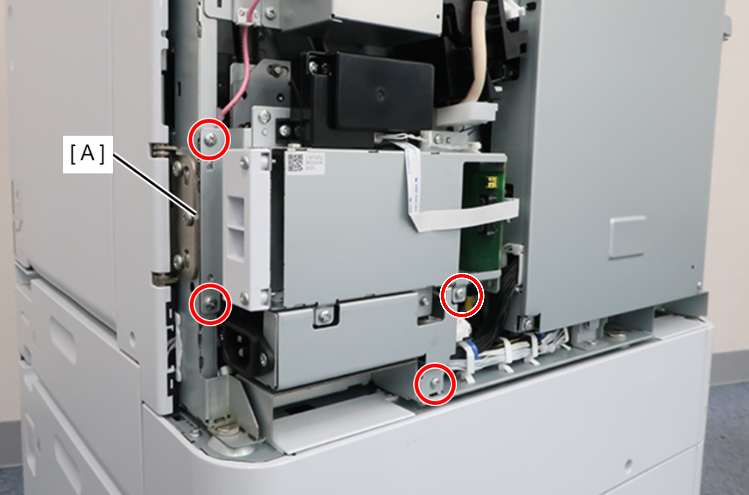
 : 3x8D
Assembly / 組み立てThe screw shown in the figure must be fastened together with the ground wire (A).
- Remove the cable from the connector (A) and remove the I/F Slot Inlet Assy (B).
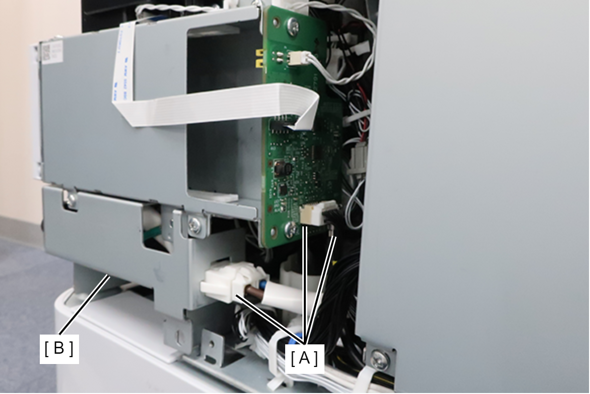
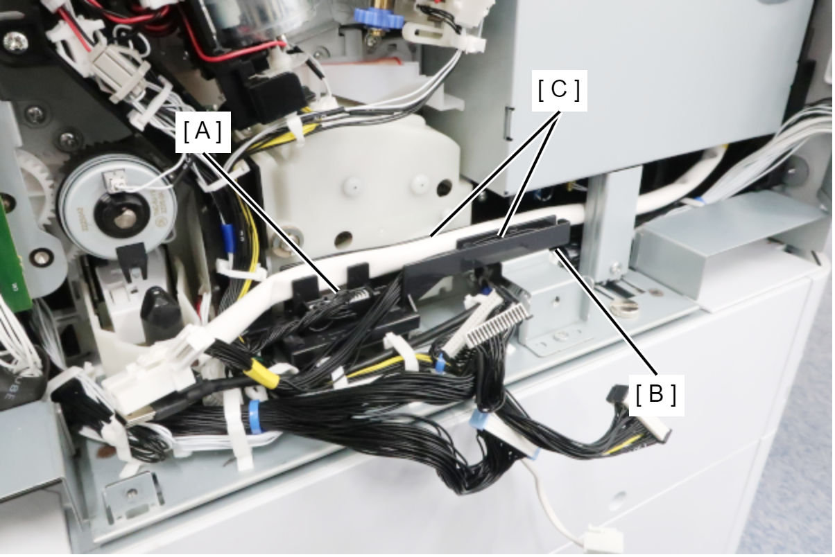
- Disconnect the cables from the connector (A) and release the 2 cables (C) from the Power Supply Cable Guide Rail (B).
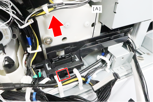
- Release the hook and remove the Power Supply Cable Guide Rail (A) in the direction of the arrow.
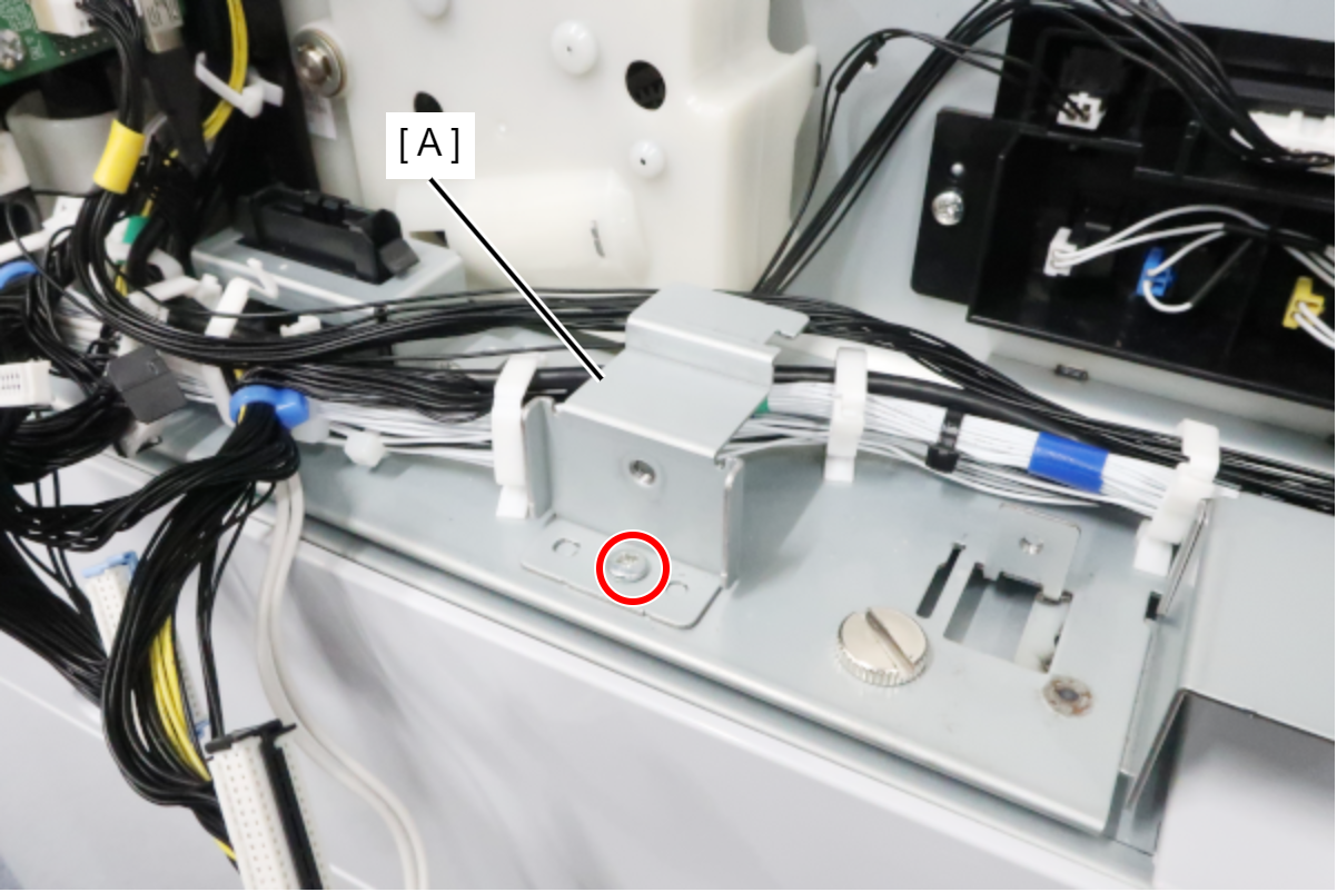
- Remove the screw and remove the Power Supply Cable Guide Rail Lower Plate (A).
- Remove the 2 screws, release the 2 hooks, and remove the Drawer Connector (A).
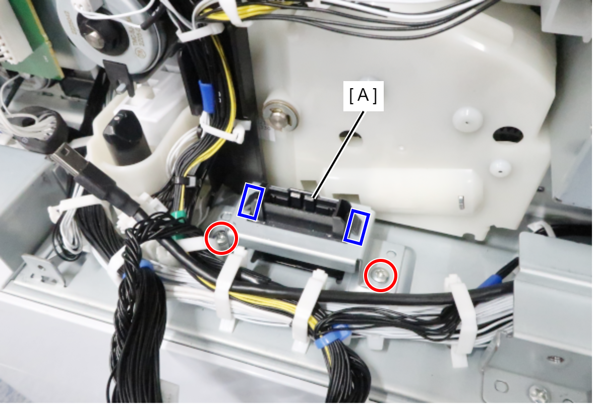
- : 3x8D
- Remove the cable from the connector (A) and release the cable from the 2 clamps (B).
- Remove the 1 screw and avoid the Wiring Rail (C).
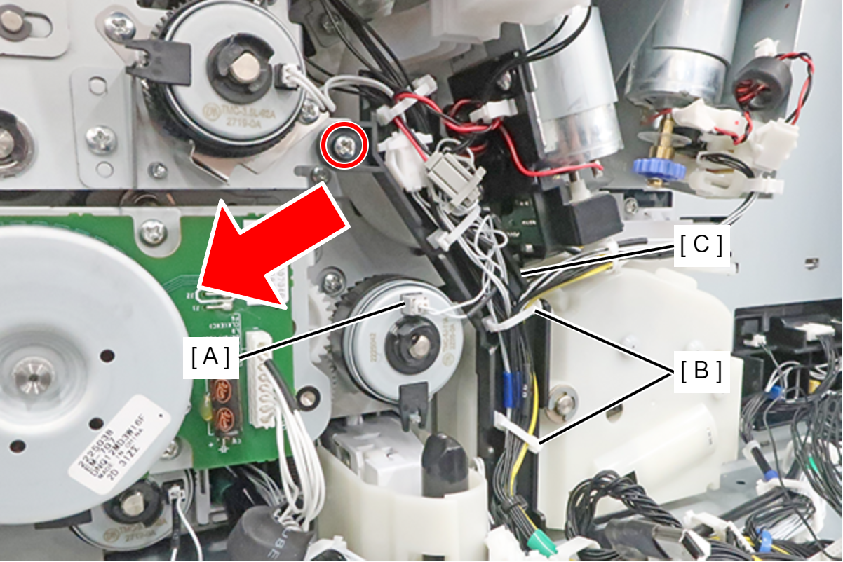
- : 3x8D
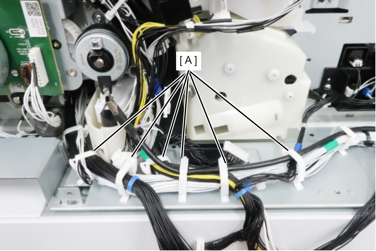
- Release the cable from 6 clamps (A).
- While avoiding the cable, remove 3 screws and remove the C1 Liftup Motor Assy (A).
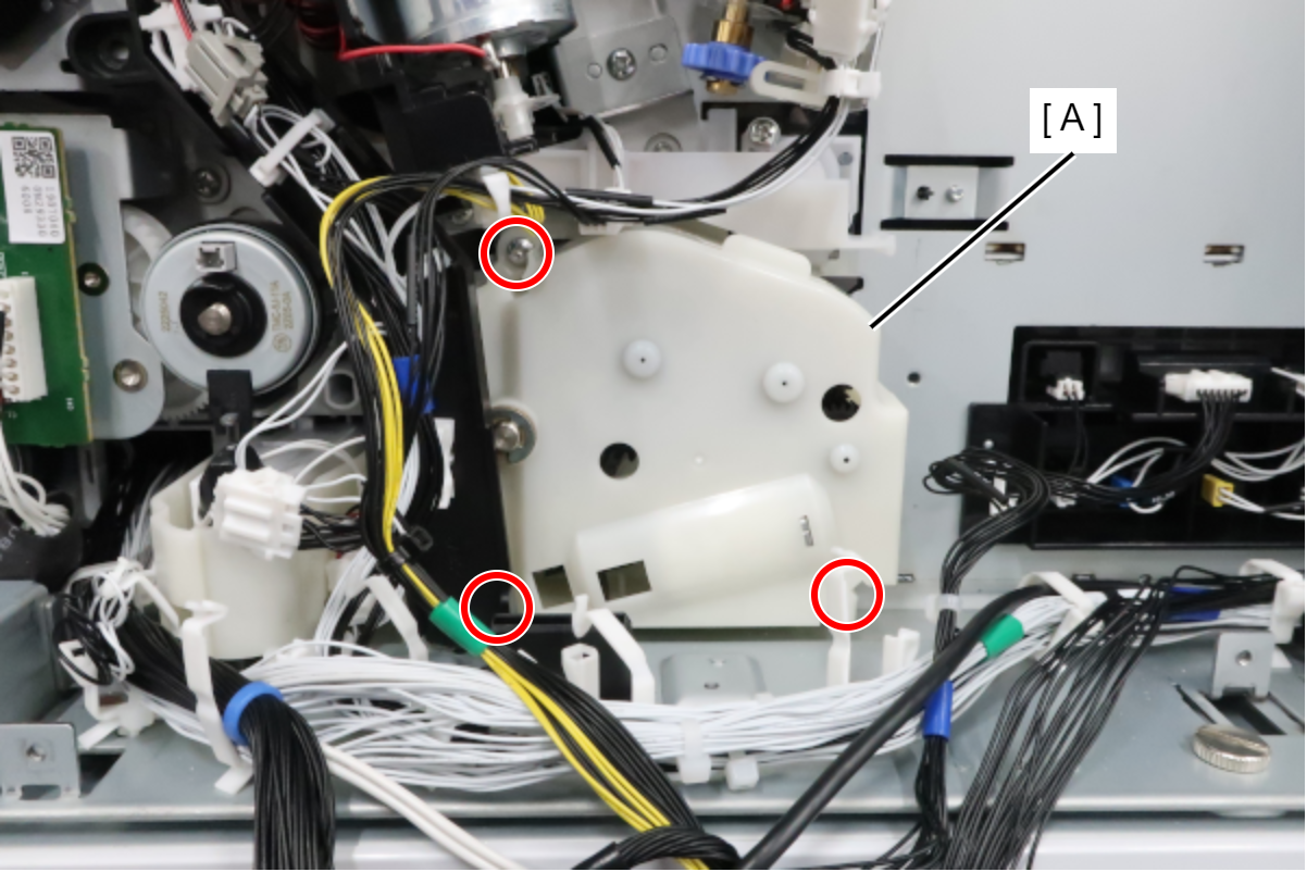
- : 3x8D
- Disconnect the cable from the 2 relay connectors (A) and remove the C1 Liftup Motor Assy (B).