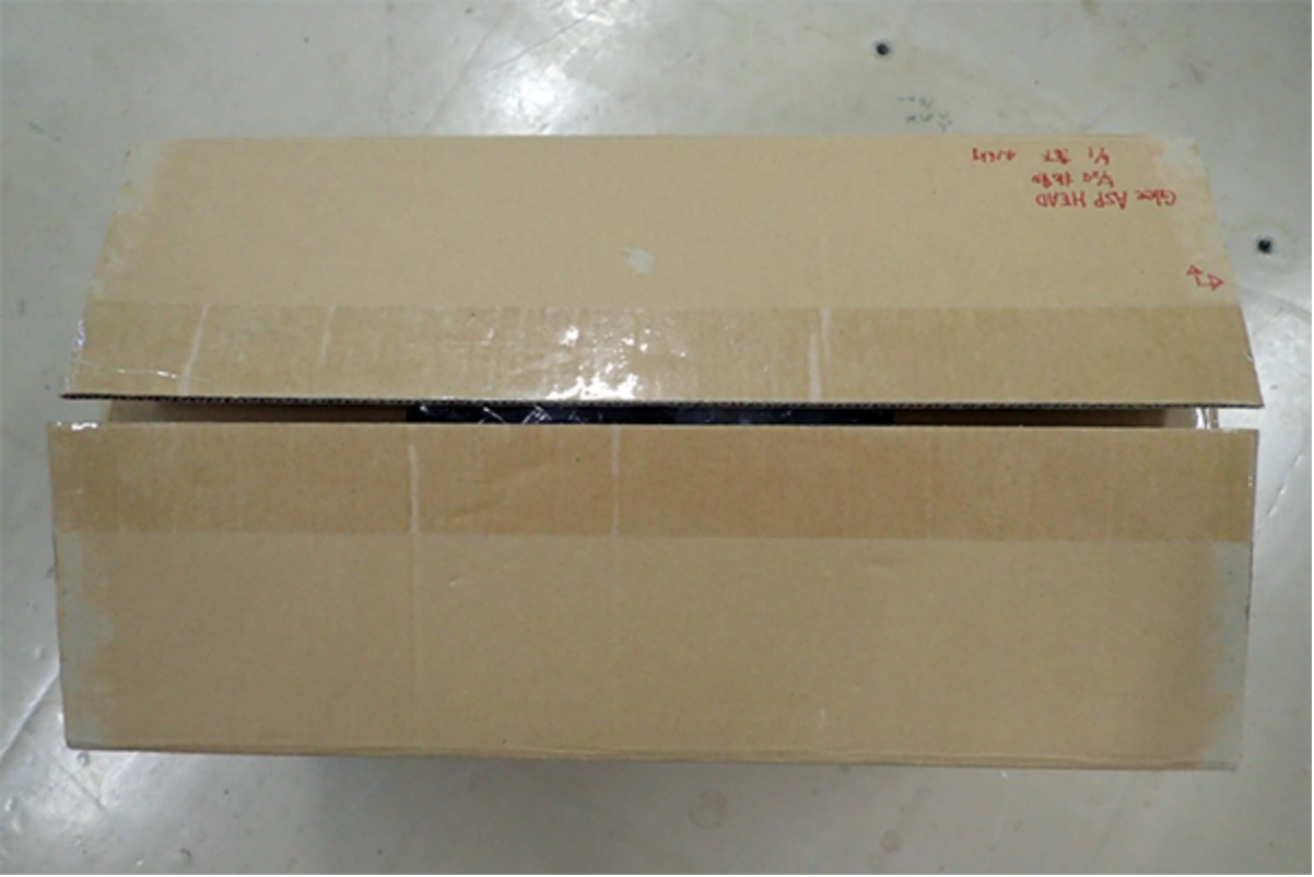
Head ASP Unpacking, Repacking, and Handling Jigs
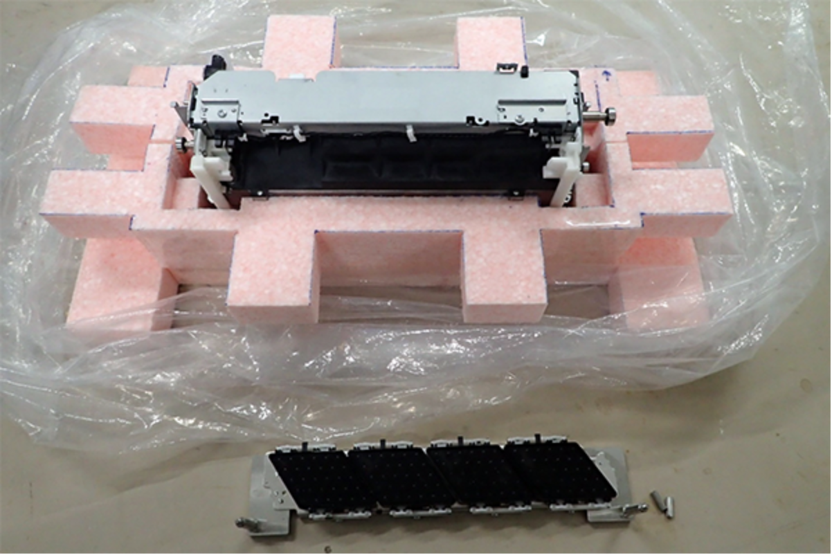
- Unpack the Head ASP box, and take out the upper and lower head pallets (1) and the head replacement kit (2) together with the bag.
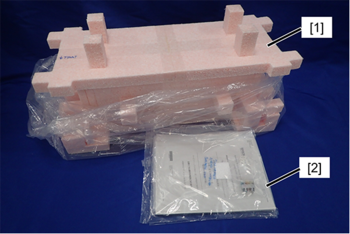
- Put head palette out.
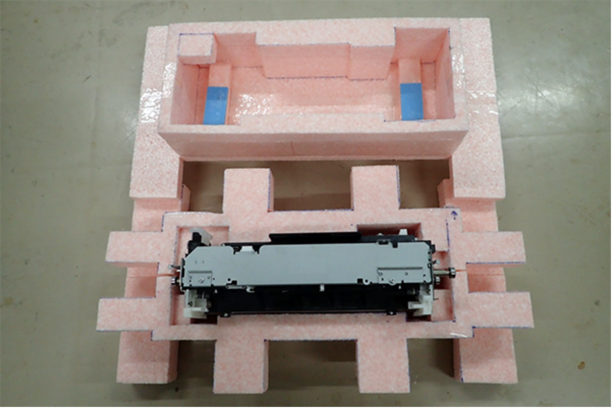
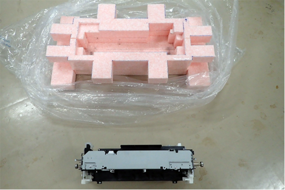
- Move the new head out from the bottom palette.
Start the service support mode and perform the before head unit replacement work.(5010101 Head)
Remove the defective Head Unit.(Head Unit)
Place the defective Head Unit (A) on the lower pallet (B) with the nozzle surface down.
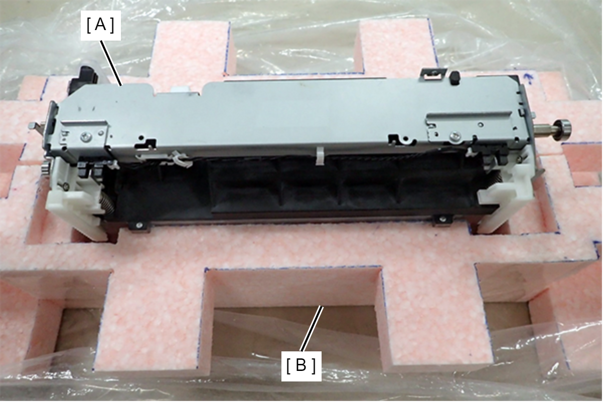
 Check Point / チェックポイント
When placing the head on the pallet, align the fixing plate and recess.
OK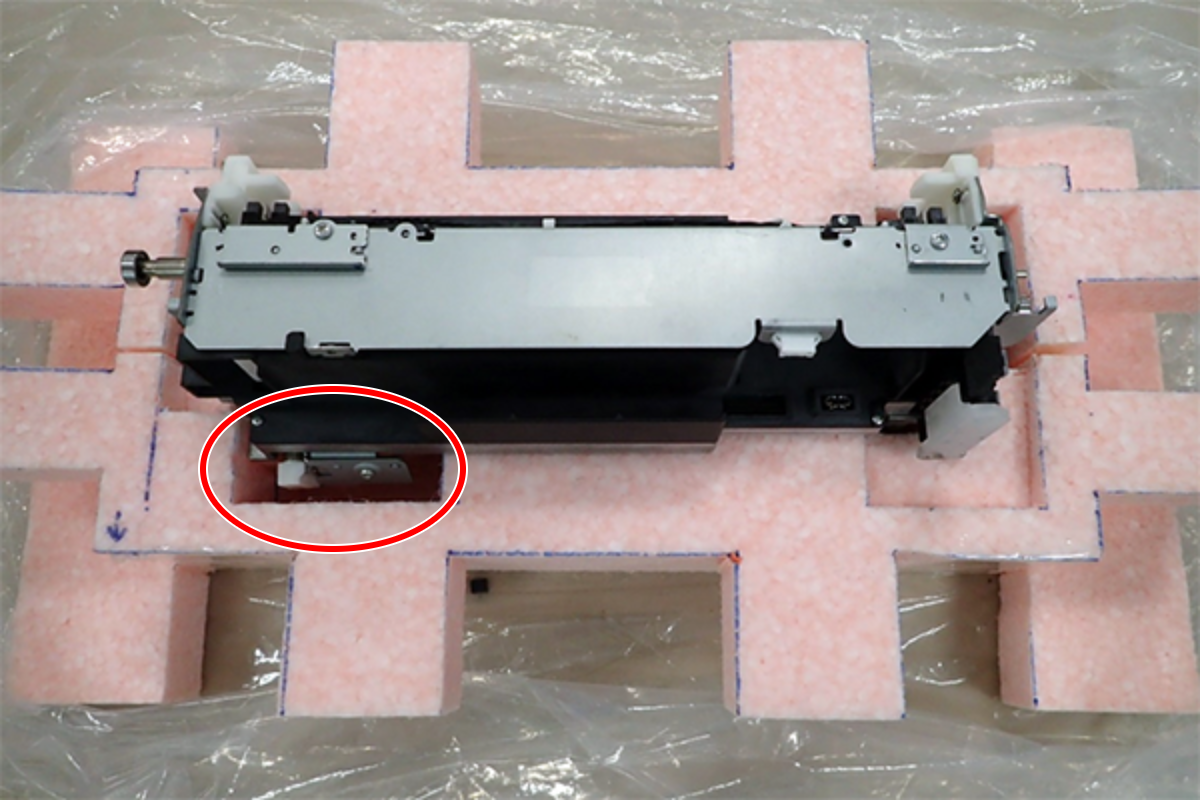
NG
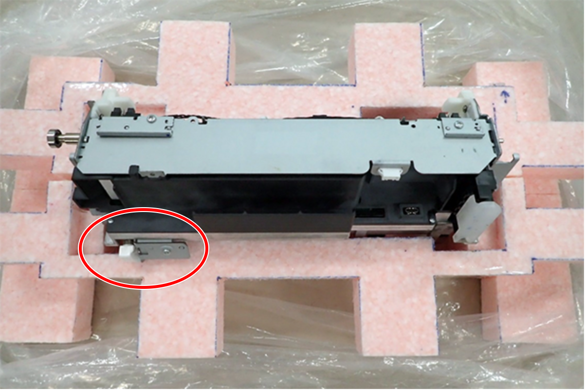
Mark the pusher (A) attached to the failed head with a pen, etc.
 Check Point / チェックポイント
It is necessary to transfer the pusher from the failed head to a new head.
Without transfer, there is a risk of errors or head rubbing.
Change the failed head placed on the pallet so that the nozzle side is toward you.

With the cap jig (A) installed, turn the new head sideways so that the pusher (B) is on top.

Remove 1 screw with the cap jig (A) still installed, and remove the pusher (B) from the new head.
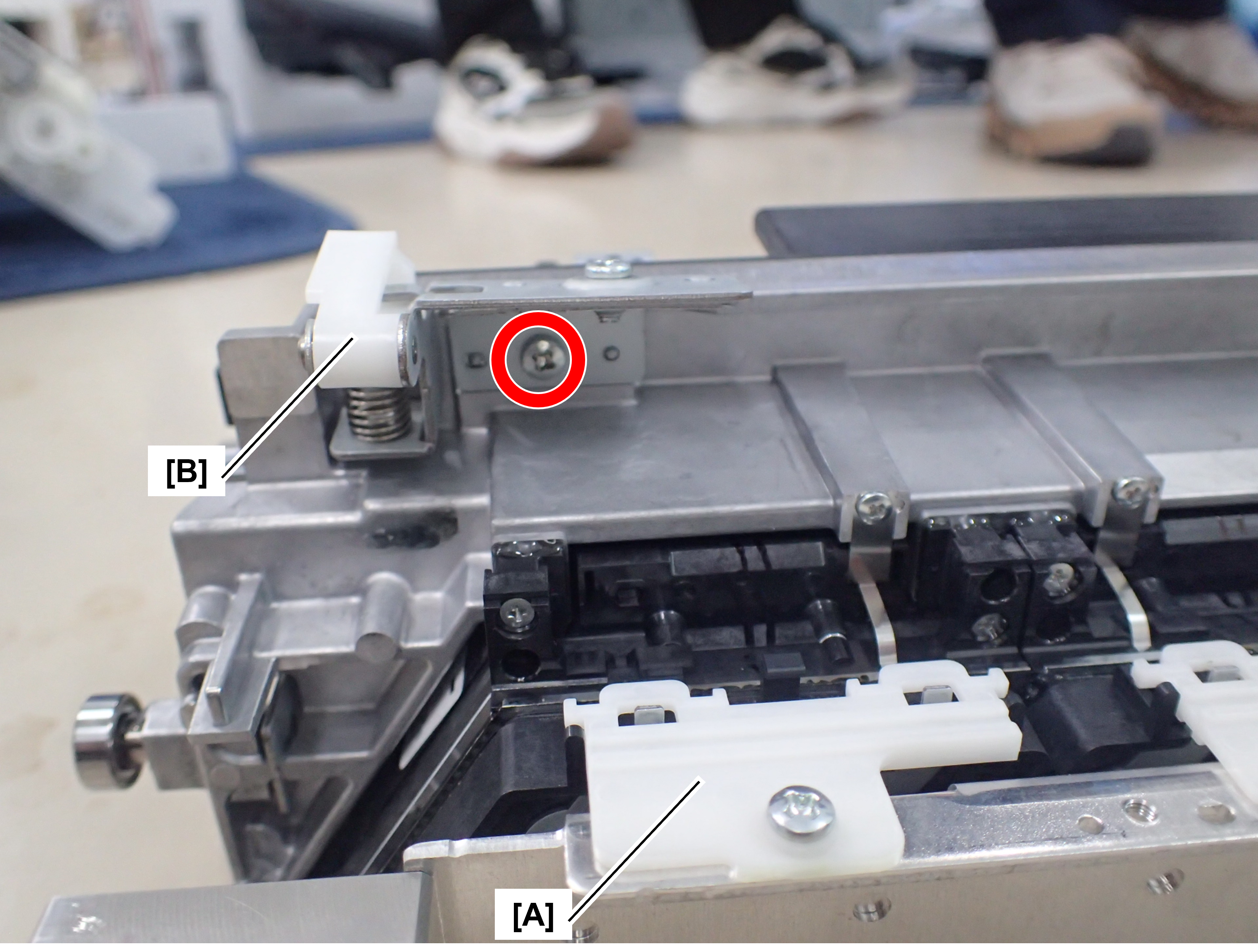
 : 3x6M
Check Point / チェックポイントThere are 2 screws on the pusher, so be sure to remove the wrong screw.
- Remove the pusher (A) (marked) of the failed head.
 : 3x6M
 - Install the pusher (marked) that was attached to the failed head that was removed in the previous step to the new head.
At this time, tighten the screws while applying light force in the direction of the arrow.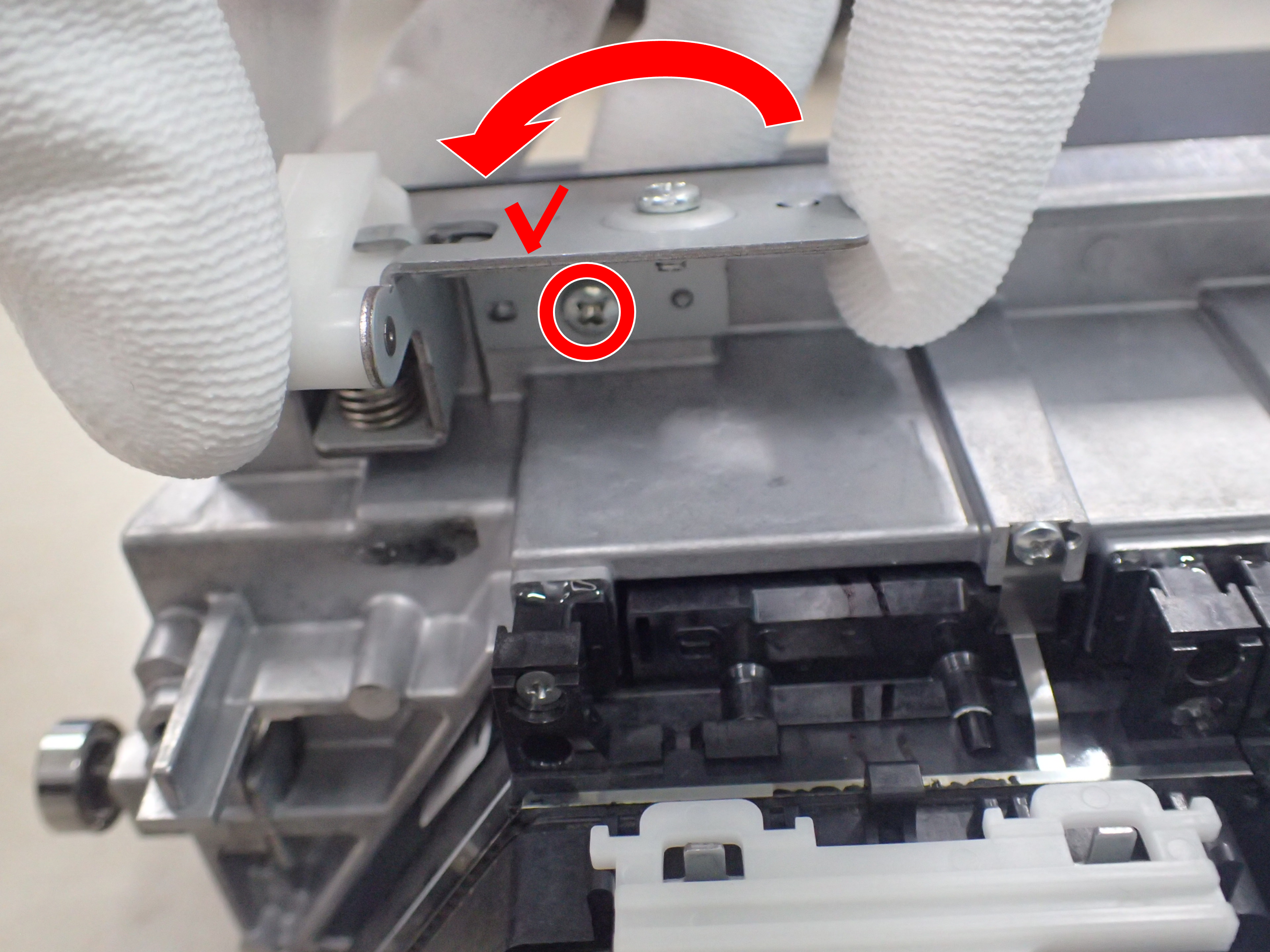
- : 3x6M
Check Point / チェックポイントWhen installing the pusher, make sure that the dowel is inserted into the alignment hole.
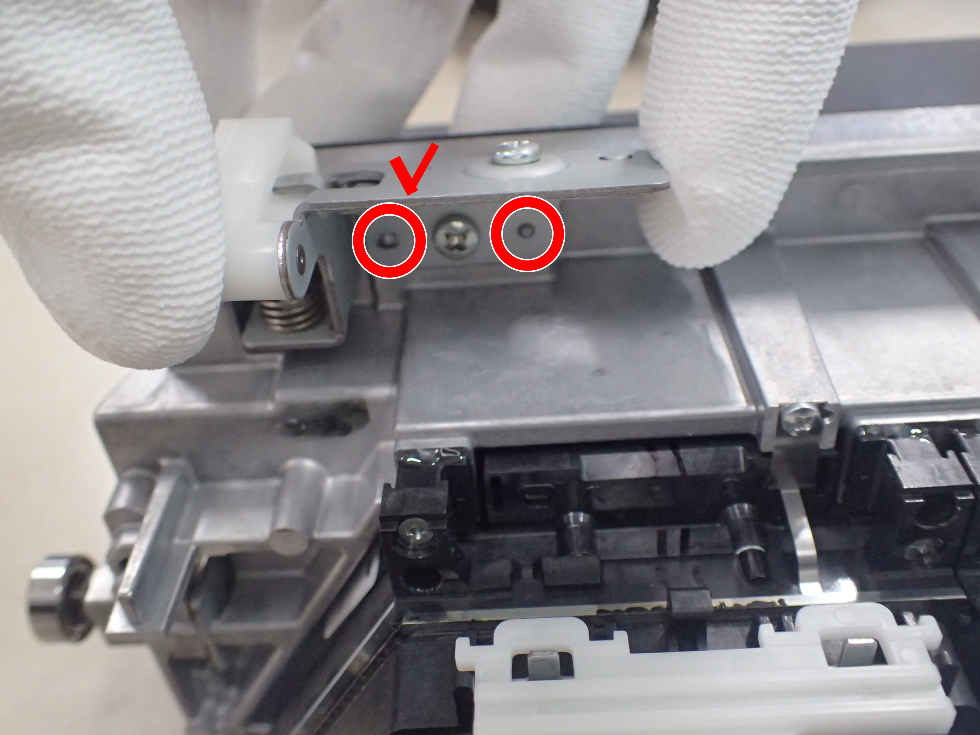
Similarly, attach the pusher removed from the ASP head to the failed head.
- Remove the two nuts (A) from the cap jig attached to the new Head Unit.
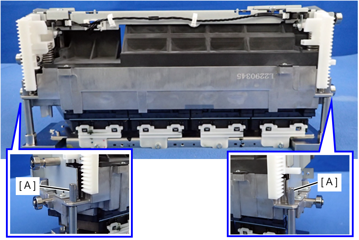
- Lift up the new head unit, remove it from the cap jig (A), and attach it to the main unit.
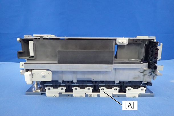
Reassemble the printer.(Head Unit)
 Caution / 注意
Be sure to attach the tubes to the defective Head Unit. Transporting the Head Unit without attaching the tubes may cause ink leakage.
Start up the service support mode and perform the menu before replacing the head unit (5010101 Head).
- Attach the cap jig to the defective Head Unit and secure it with the nuts.
 important / 重要
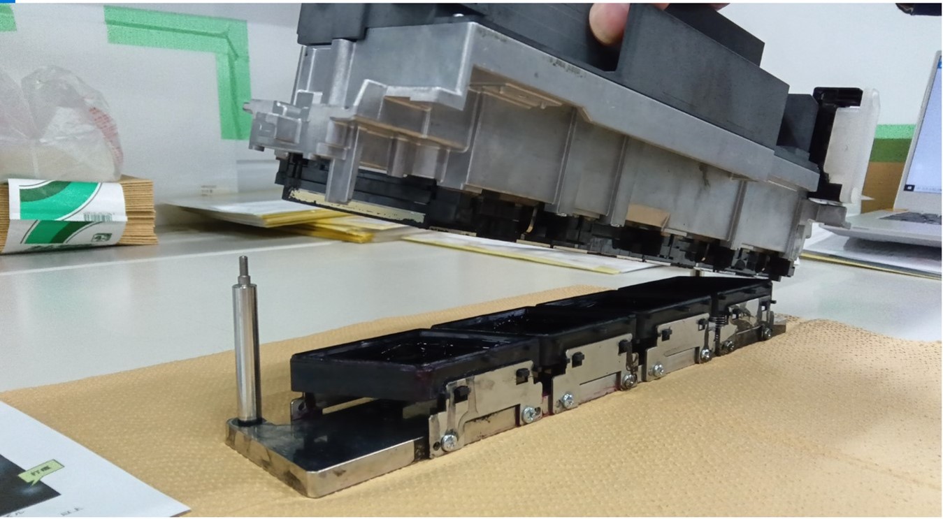
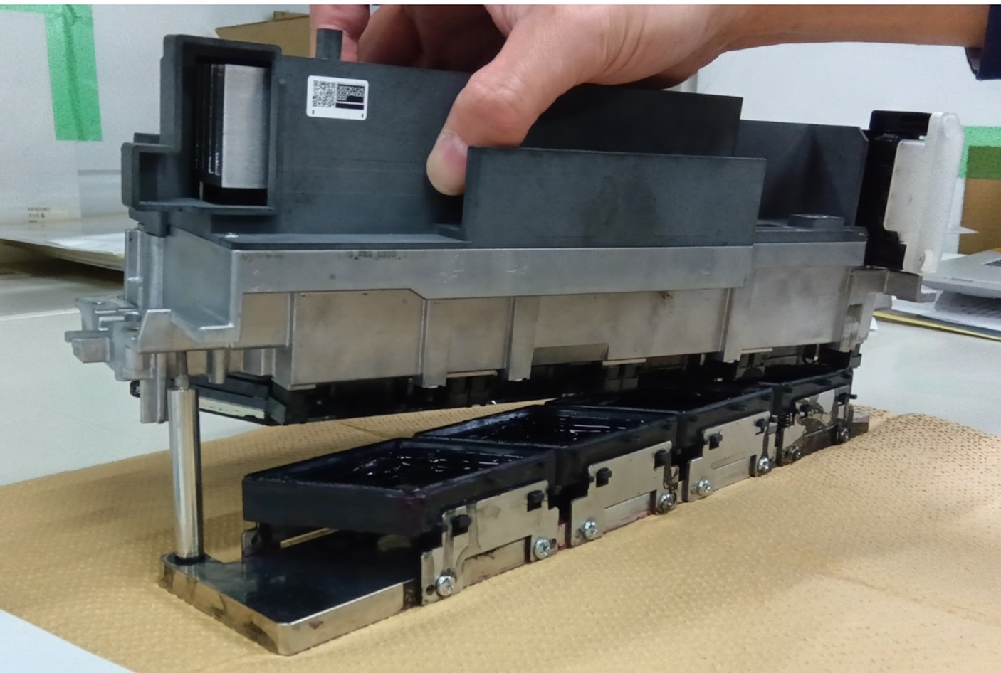
- When installing the head unit to the cap jig, the cap jig support may hit the nozzle surface.
Therefore, when installing the cap jig, follow the steps below.
install the head unit diagonally to the cap jig and insert the cap jig support of one.
Then, insert the other cap jig support.
- If the nuts are not tightened enough, ink leakage may occur. Make sure the nuts are tightened securely.
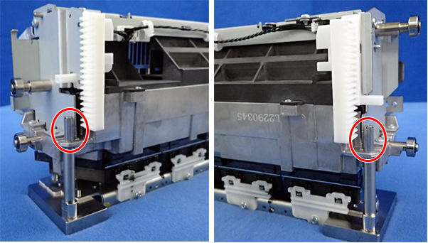
- The Head Unit has four holes through which the cap jig can be inserted, but two are not used.
Make sure that the ink supply tube (A) and the pins (B) of the cap jig are facing toward you, and the nuts are inserted in the correct holes (C).
If the Head Unit or jig is oriented incorrectly, the screw heads interfere with the Head Unit and the nuts cannot be tightened.
- When installing the head unit to the cap jig, the cap jig support may hit the nozzle surface.
- Place the defective Head Unit onto the lower head palette with the nozzle side down.
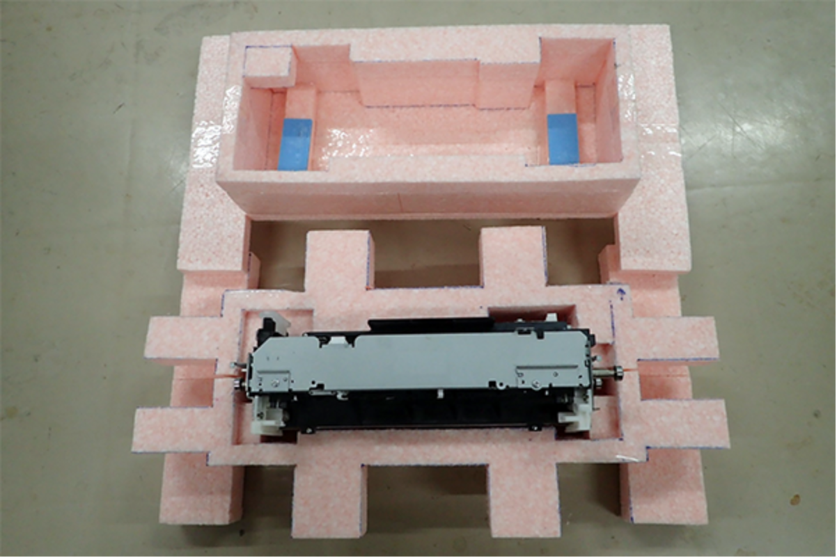
Attach the upper head pallet, and put the defective Head Unit set into the head packing bag in which the new Head Unit was placed. If the plastic bag is torn, use the spare head packing bag.
Check Point / チェックポイントThe head packing bag does not have a zipper.
Fold or roll the opening of the bag several times to prevent the bag from opening. If possible, tape the opening of the bag.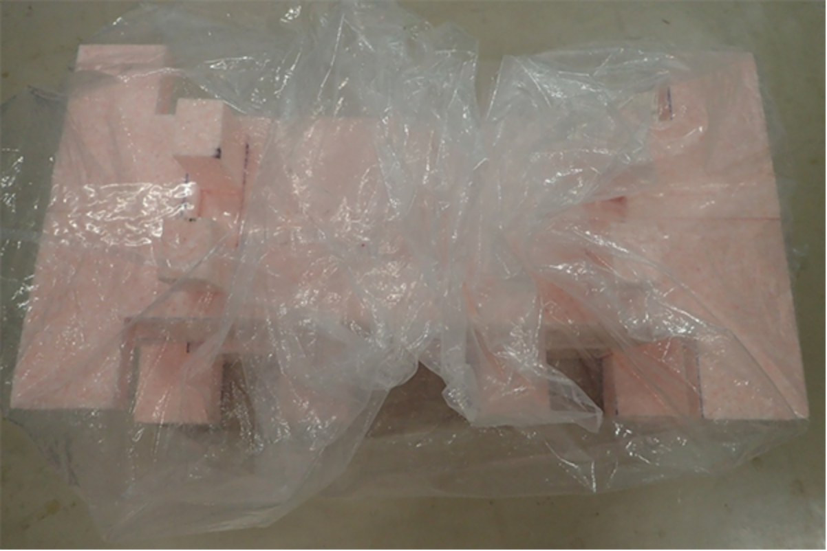
- Put the bagged Head Unit set into the plastic bag used for the new Head Unit set, and then put it in the box.
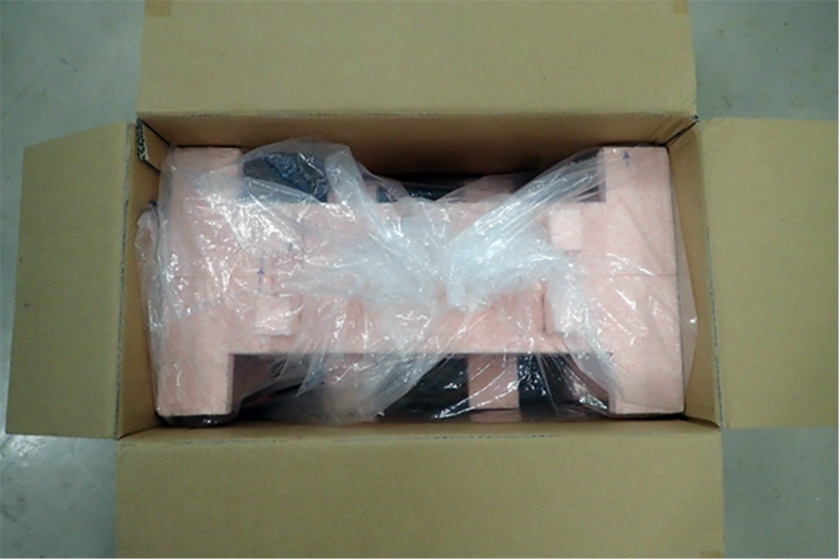
- Close the box and tape it securely.