
Ink System Unit
 Check Point / チェックポイント Check Point / チェックポイント |
When replacing this part, you need to run the menu from the service support mode before replacing it. |
- Remove the screw and remove the Left Cover Upper (A) in the direction of the arrow.
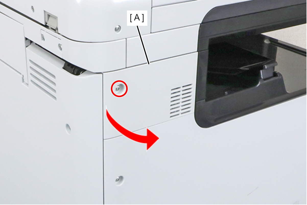
 : 3x8D
- Remove the 4 screws and remove the SCN Fixing Plate (A).
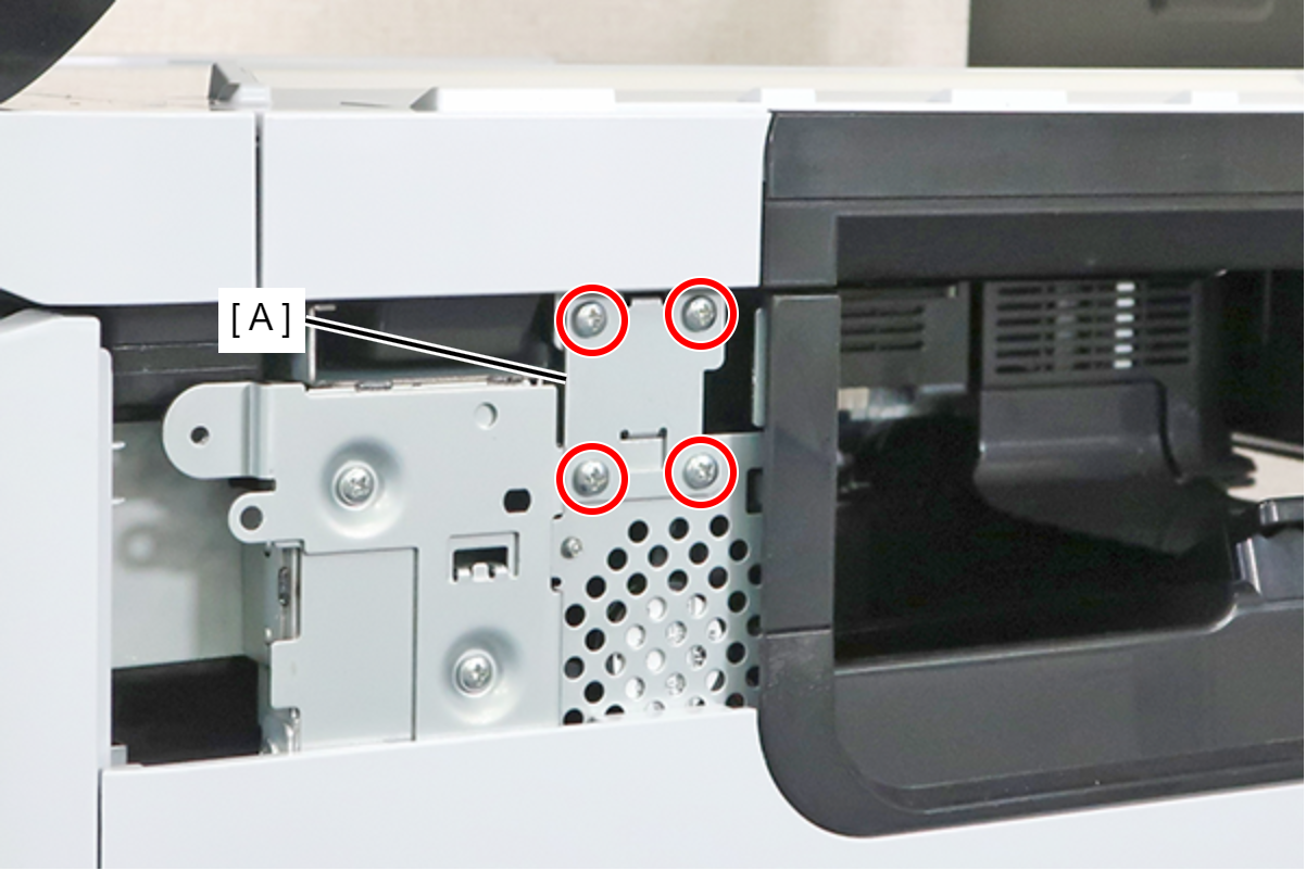
- : 3x8M
 Caution / 注意
Be sure to completely remove the SCN Fixing Plate.
If you attempt to carry out the operation without completely removing the screws and leaving the lower 2 screws removed, there is a risk of an accident, such as pinching your finger, when opening or closing the SCN.
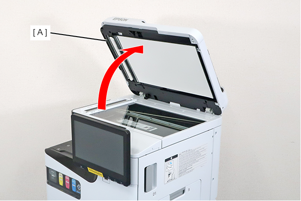
- Open the ADF (A).
- Remove the screw and slide the Panel Upper Cover (A) in the direction of the arrow to remove it.
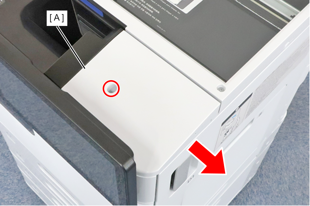
- : 3x8D
- Remove the 2 screws and the spacer.
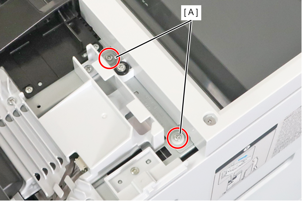
- : 3x8D
- Remove the screw and remove the spacer (A).
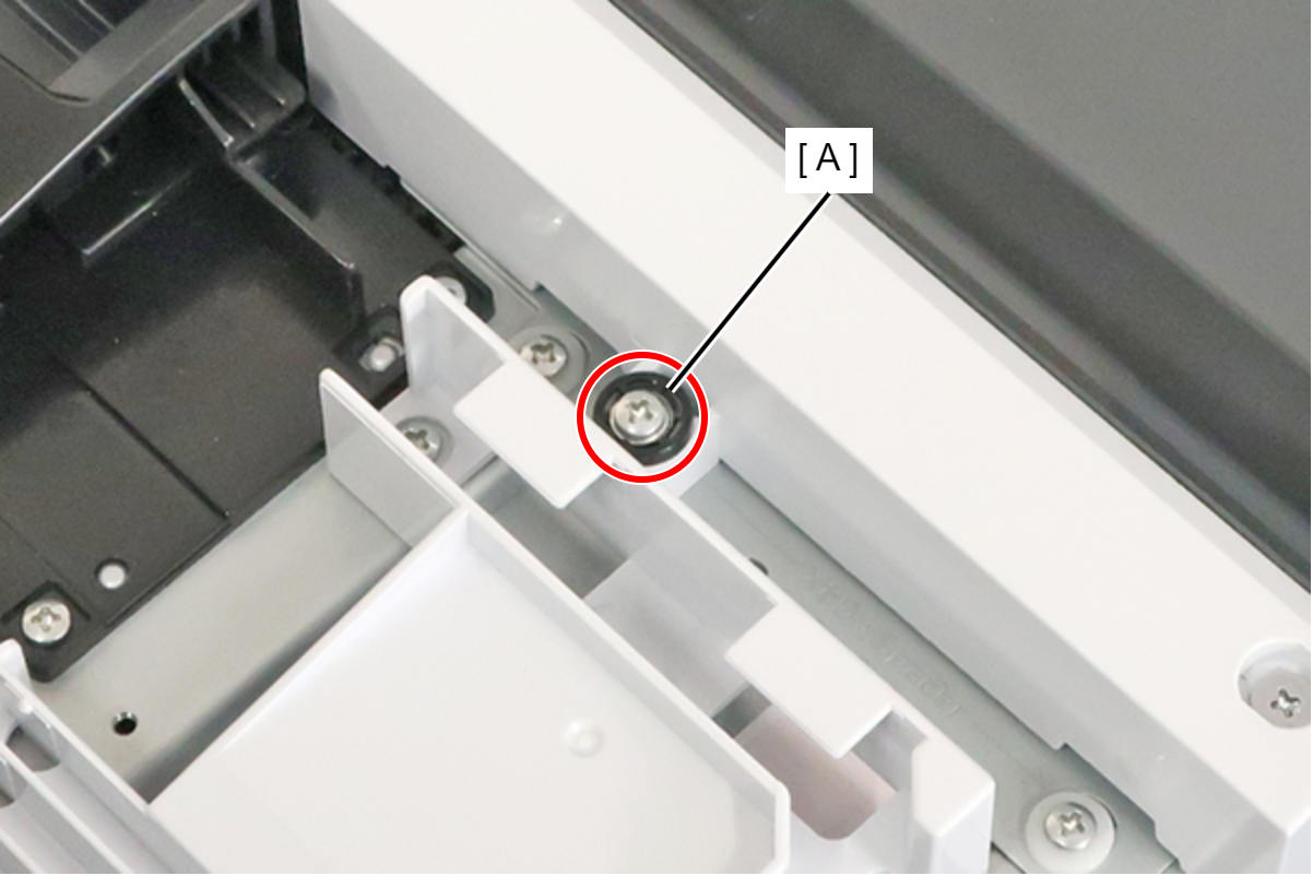
 : 3x18MW
- Remove the screw, and attach the spacer (A) removed in the preceding step.
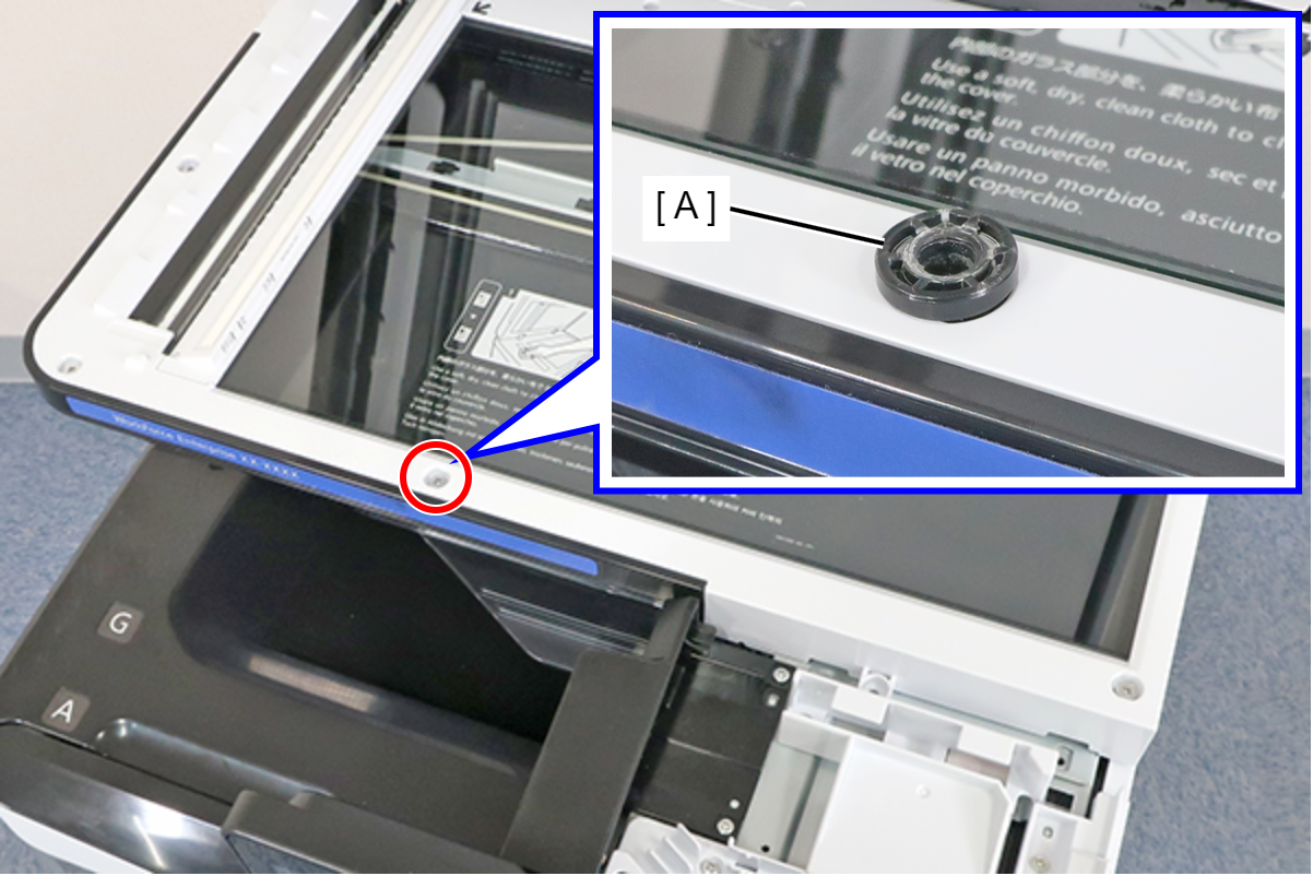
- : 3x5D
- Close the ADF (A), and fix the ADF and SCN Unit (B) with the screw that had been fixing the spacer in place.
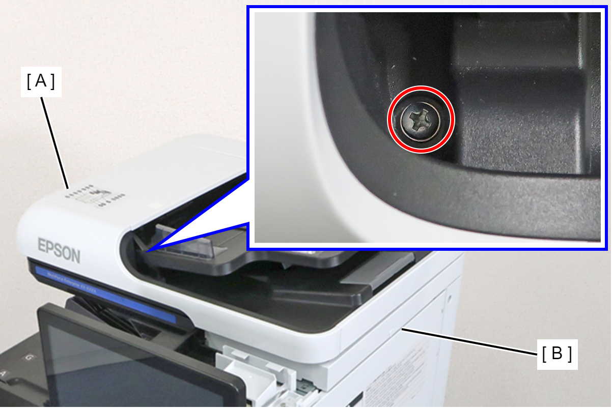
- : 3x18MW
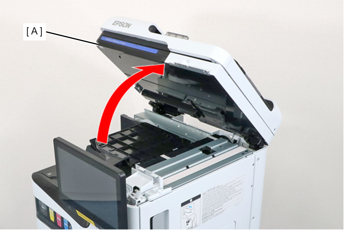
- Raise the ADF/SCN Unit (A).
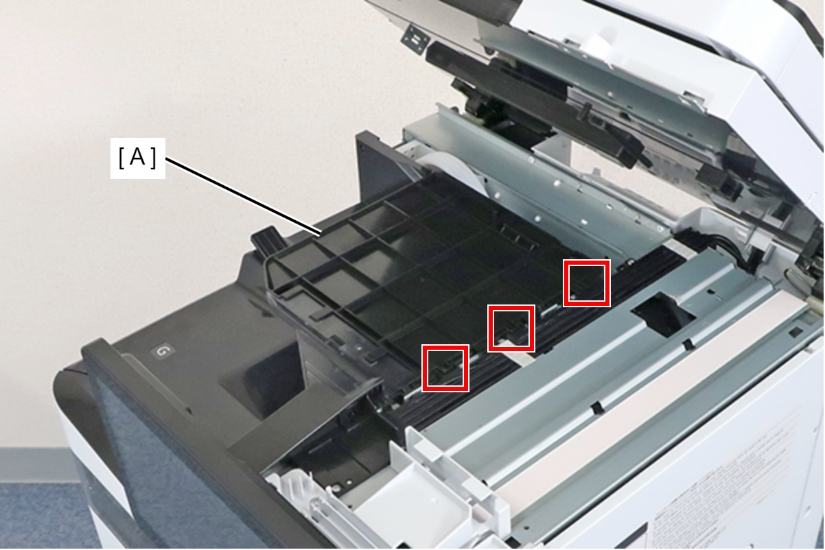
- Lift the duplex tray Assy (A), remove the 3 hooks, and remove the duplex tray Assy (A).
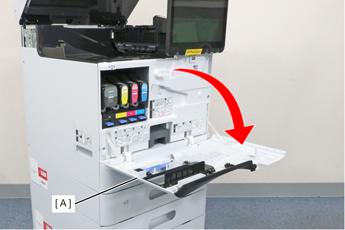
- Open the Front cover (A).
- Remove 4 screws and remove the FD Stacker Assy (A).
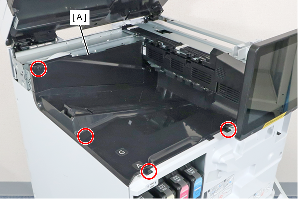
- : 3x8D/BK
- Remove the 2 screws and remove the IC Guide (A).
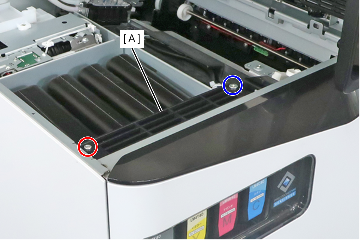
- : 3x8D
 : 3x5D
- Remove the 2 screws and remove the Head Joint (A).
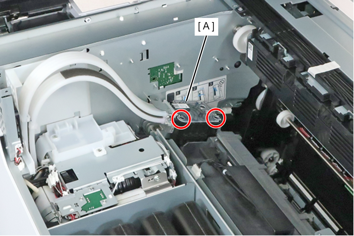
- : 3x20M
Check Point / チェックポイントThe screws are provided with a stopper, so they cannot be completely removed.
 Note / 補足
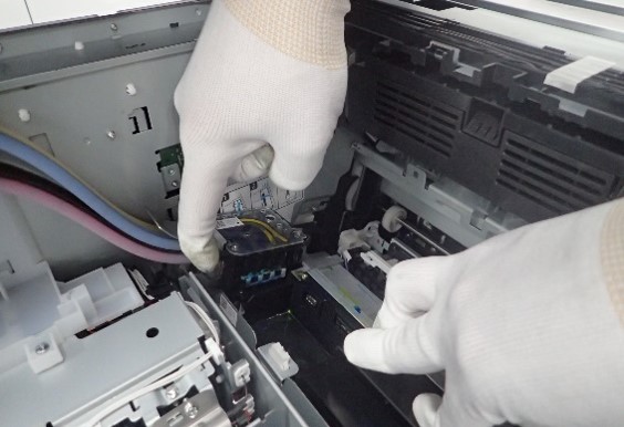
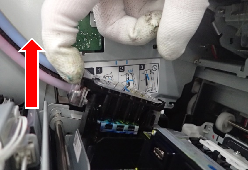
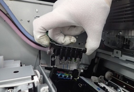
To remove the head joint, follow the procedure below.
1. Place your hand on the head and place your finger on the edge of the joint
2. Lift upwards with your hooked fingers, lift one side and then lift the whole thing upwards.
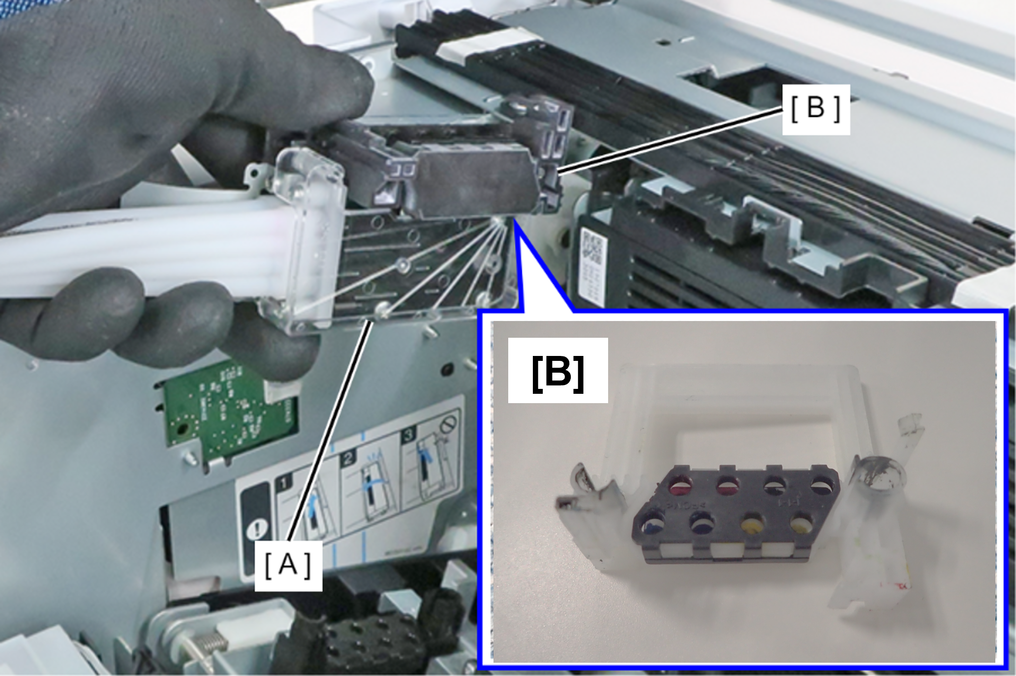
- Attach the protective cap (B) to the connector of the Head Joint (A).
 Caution / 注意
There is a risk that ink will drip, so do not shake the Head Joint strongly before attaching the protective cap.
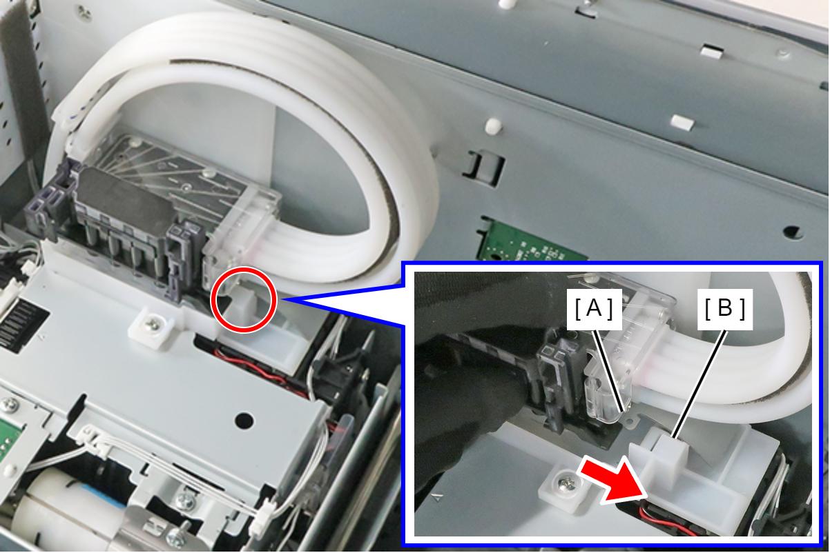
- Fix the Head Joint by engaging the frame protrusion (A) of the Head Joint with the Ink System Unit hook (B).
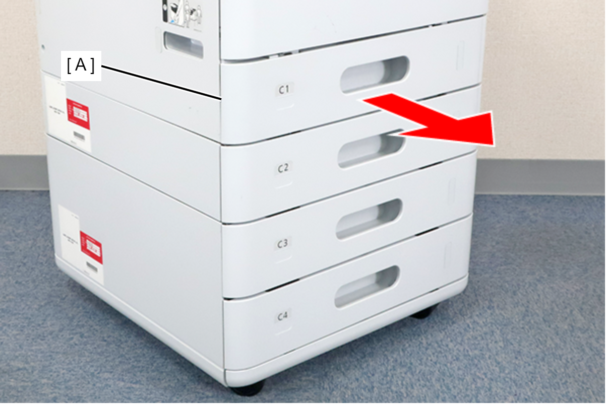
- Remove the C1 cassette (A).
- Remove the Ink cartridges (A).
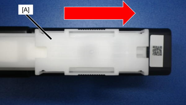
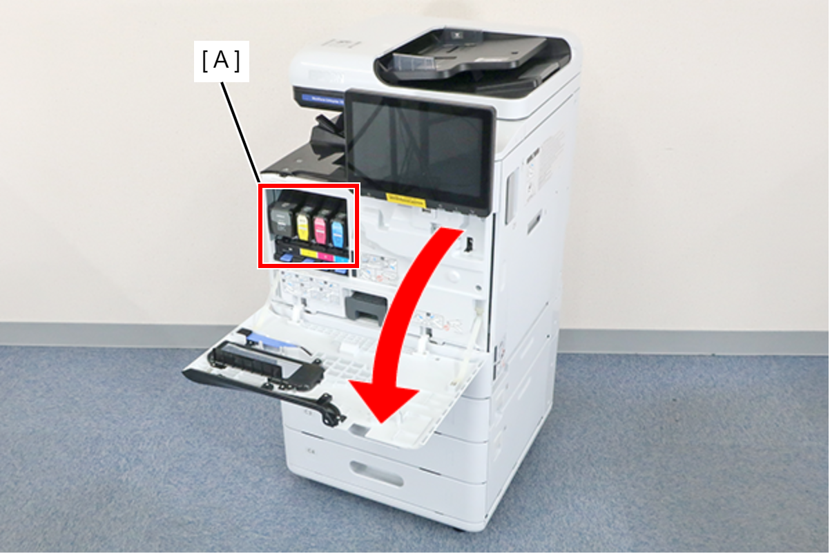 Note / 補足
Be sure to attach the ink supply port cap (A) to prevent ink dripping from the ink cartridge supply port.
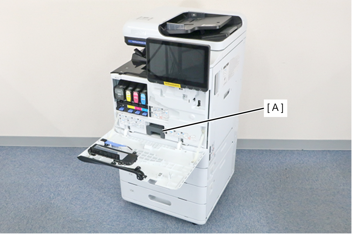
- Remove the Maintenance Box (A).
- Remove the 7 screws and remove the Front Inner Cover (A).
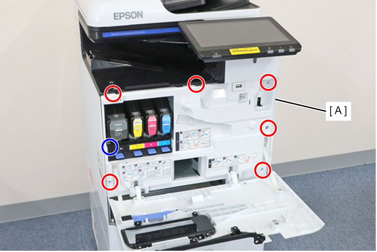
- : 3x8D
- : 3x8D/BK
 Assembly / 組み立て
Insert the protrusion (A) of the Front Inner Cover into the hole (B) of the main unit and install.
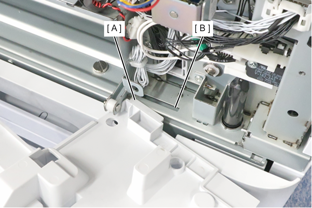 Note / 補足
If the wireless LAN unit (A) is installed, remove it.

- Remove the 3 screws and remove the left cover lower (A) in the direction of the arrow.
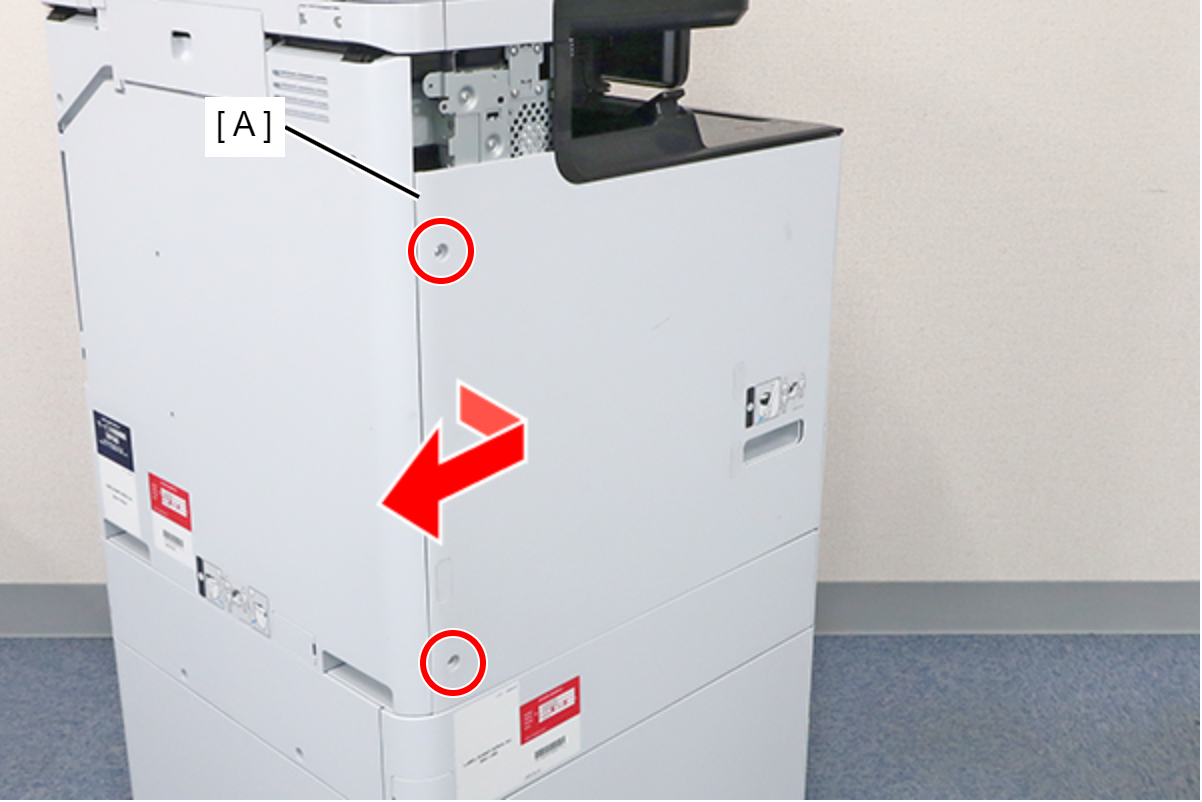
- : 3x8D
Assembly / 組み立てAlign the 6 hooks on the Left Cover Lower with the holes on the main unit and attach it.
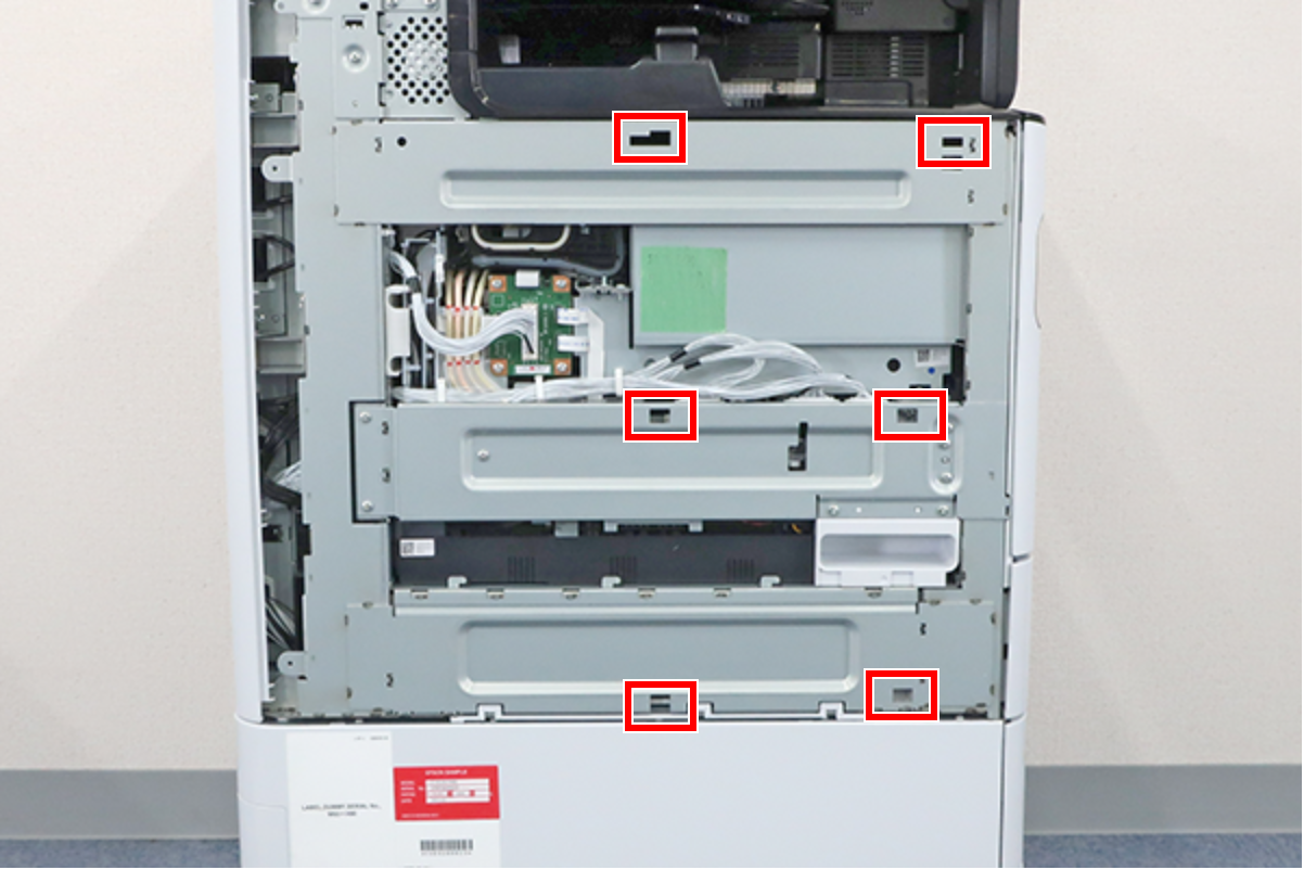
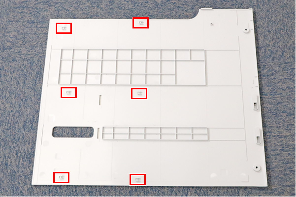
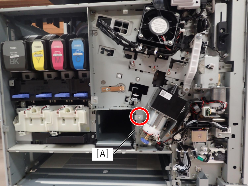
- Remove 1 fixing screw from the motion cover plate (A).
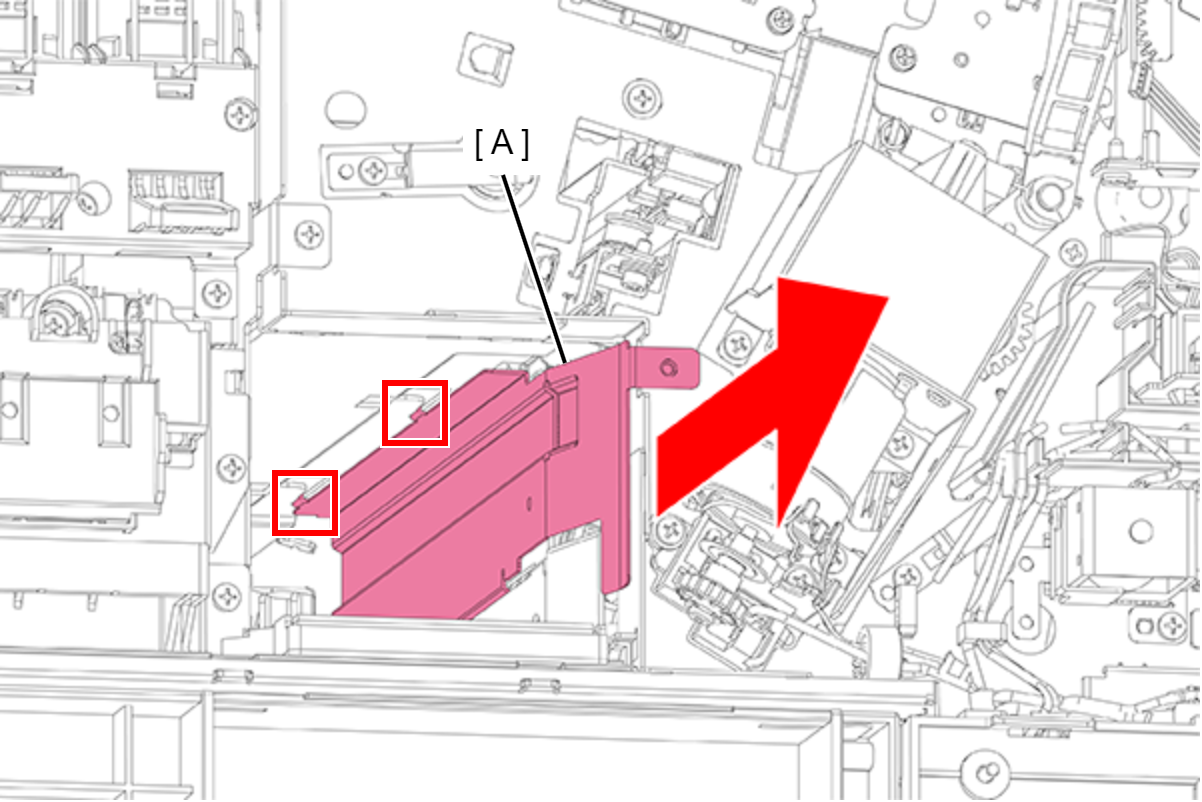
- Slightly pull out the motion cover plate (A) to disengage the two hooks.
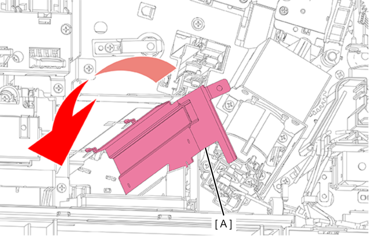
- Tilt the motion cover plate (A) to avoid hitting against other components and remove it.
- Remove the 6 screws and remove the Handle Frame (A).

- : 3x8D
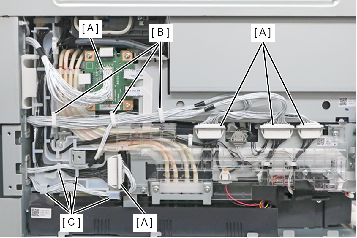
- Remove the cables (white) from the 5 connectors (A), and release the cables from the 3 clamps (B) and the 5 guides (C).
- Remove the screw, and pull out the Ink System Unit (A) until the position where it stops.
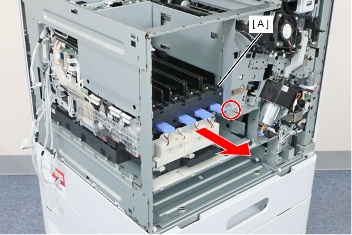
- : 3x8D
- Remove the 2 screws and remove the waste ink joint (A).
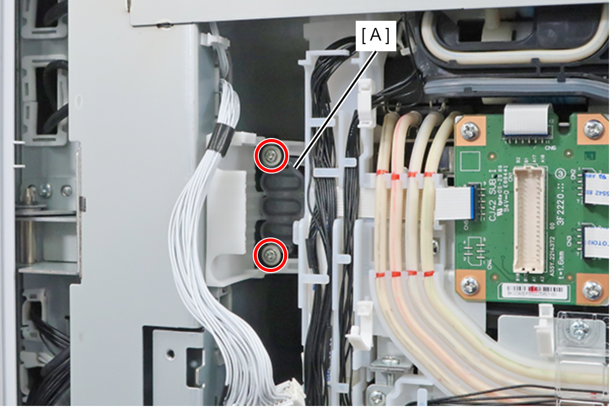
- : 3x16DC
Check Point / チェックポイントThe screws are provided with a stopper, so they cannot be completely removed.
- Lift the front side of the Ink System unit (A), and pull it out until the positions of the 2 triangular marks (B) are aligned.
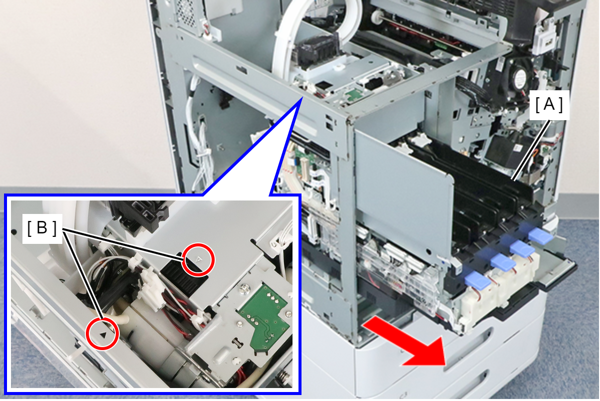
- Insert the waste liquid fitting jig (A) into the waste liquid fitting (B) of the ink system unit.
 Note / 補足
- The waste liquid joint jig is used to prevent ink leakage when removing the ink system unit.
- Remove the Head Joint (A), remove the 2 screws, and remove the IS Tube Guide (B).
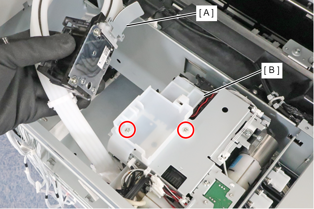
- : 3x10M
Check Point / チェックポイントThe screws are provided with a stopper, so they cannot be completely removed.
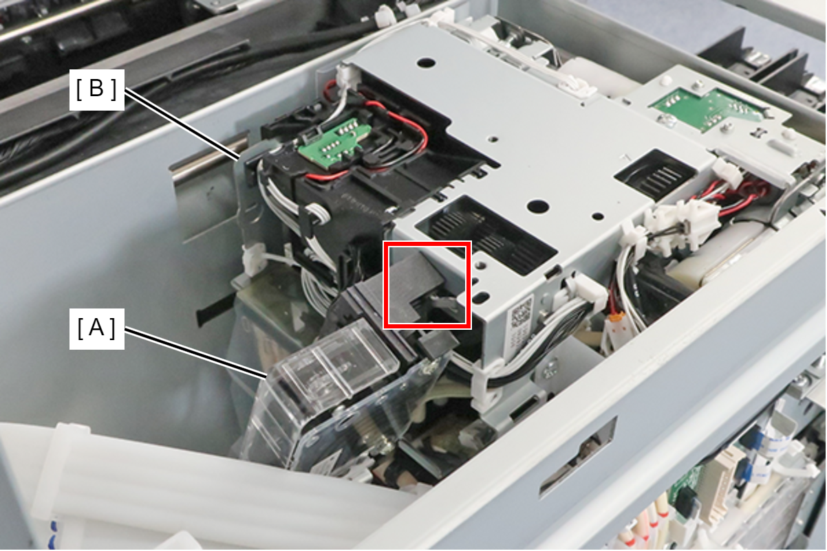
- Engage the hook, and fix the Head Joint (A) to the rear side of the Ink System Unit (B).
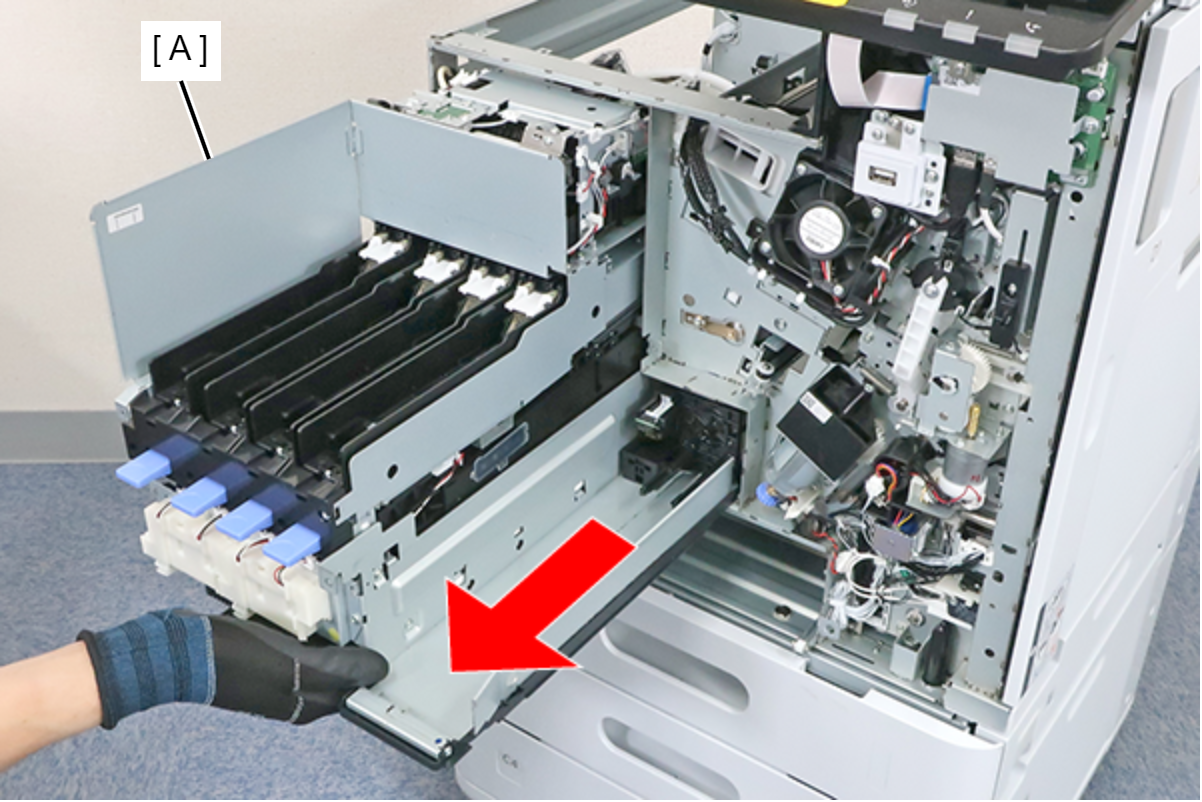
- Hold the front side, and pull out the Ink System Unit (A) until the position where it stops.
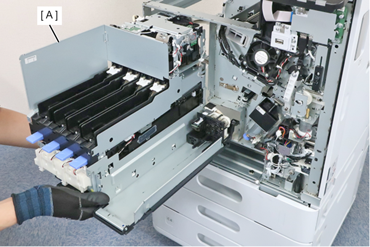
- Support the rear side of the Ink System Unit (A) from below, and remove the Ink System Unit.
 Caution / 注意
- Before installing a new Ink System Unit, disconnect one of its tubes (A) that has a red line marking. Do not disconnect the other tubes that do not have the red line marking.
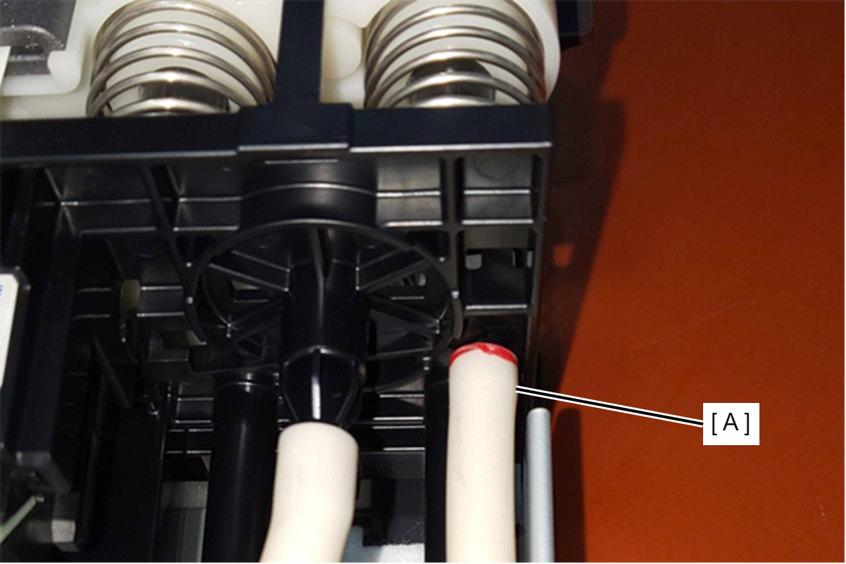
- Be sure to first attach the motion cover plate as described in step 23, then insert your hand through the a rectangular hole for maintenance box and remove the tubes.
Attaching the motion cover plate described in step 23 after removing the tubes may damage the needles for installing the maintenance box.
Assembly / 組み立てIf there is ink on the product during assembly, wipe it off with cloth etc.
- Before installing a new Ink System Unit, disconnect one of its tubes (A) that has a red line marking. Do not disconnect the other tubes that do not have the red line marking.
| Check Point / チェックポイント |
After replacing this part, you need to run the menu from the service support mode. (If you ran the Before-replacement menu before replacing the part, it will start automatically when you turn the power on.) |