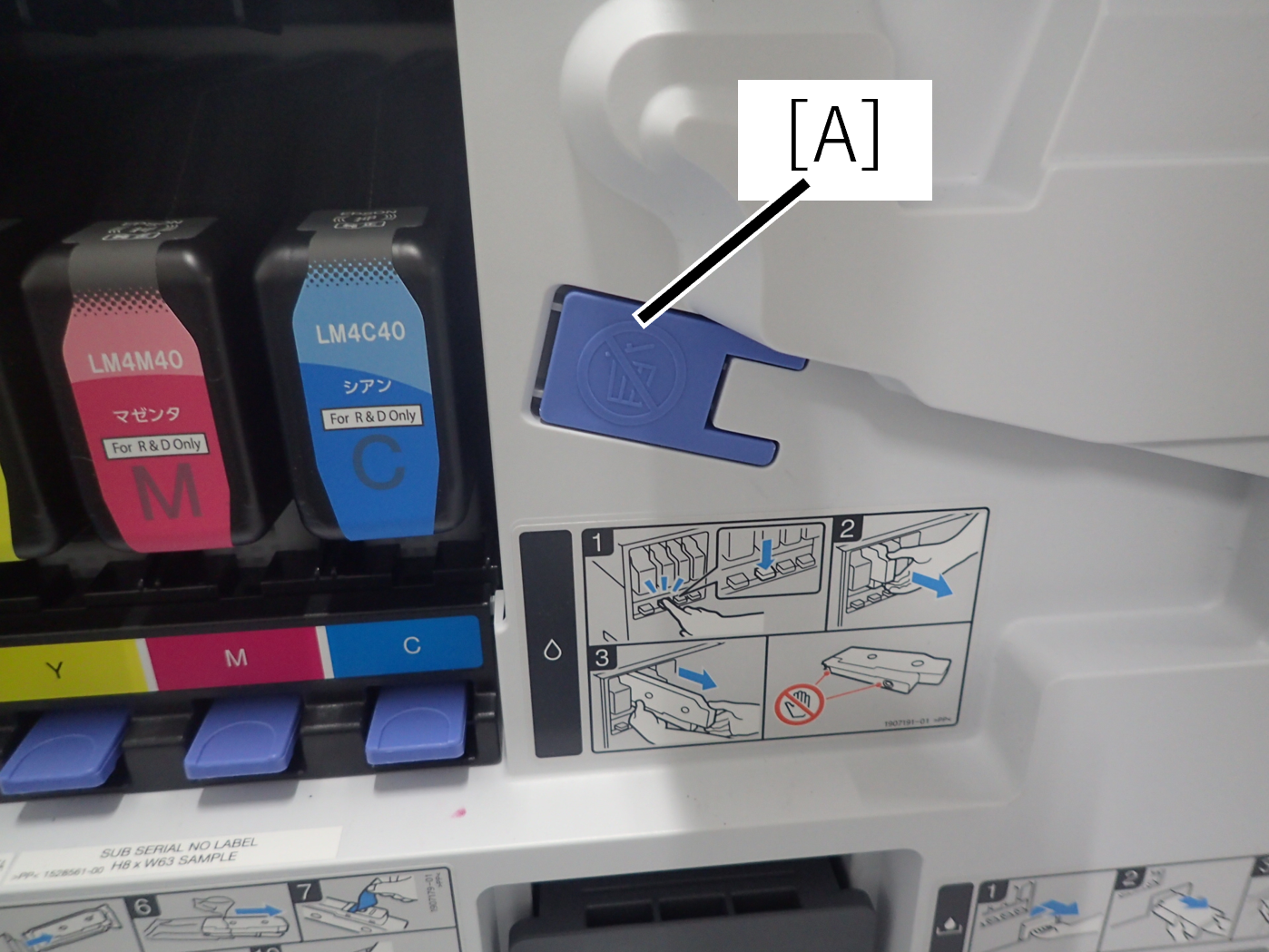
Transport Preparation menu of Service support mode cannot be executed
If you cannot turn on the power of the main unit due to a failure or other reason, and you cannot execute pre-transport preparations from the service support mode, you need to manually close the 2 valves (selector valve and flow path valve 1) according to the following procedure.
* Tube clips supplied as ASP are required. Please purchase them.
- Remove the 3 screws and remove the left cover lower (A) in the direction of the arrow.
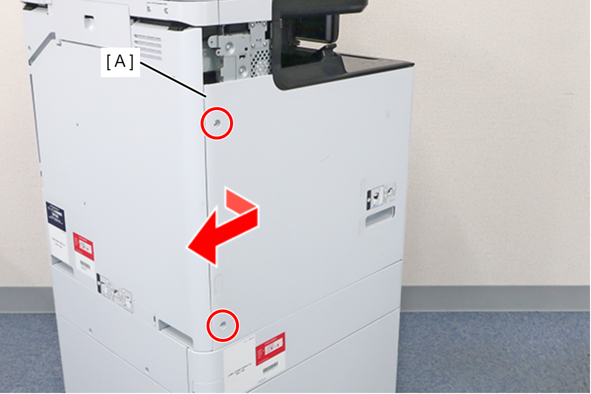
 : 3x8D
 Assembly / 組み立て
Align the 6 hooks on the Left Cover Lower with the holes on the main unit and attach it.
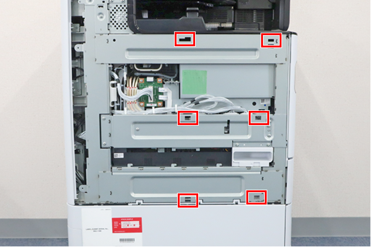
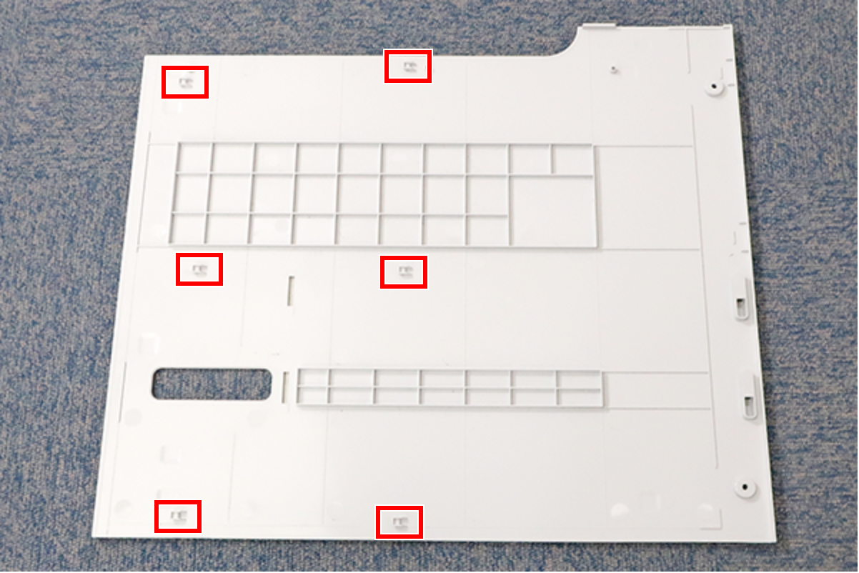
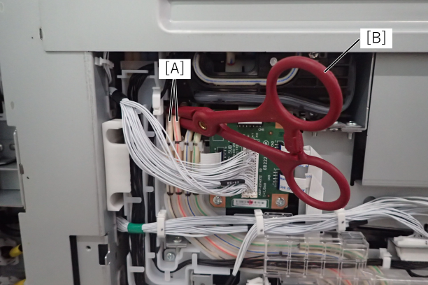
- Insulate the two air tubes (A) of the selector unit with tube clips (B). By doing this work, the condition is the same as when the selector valve is closed.
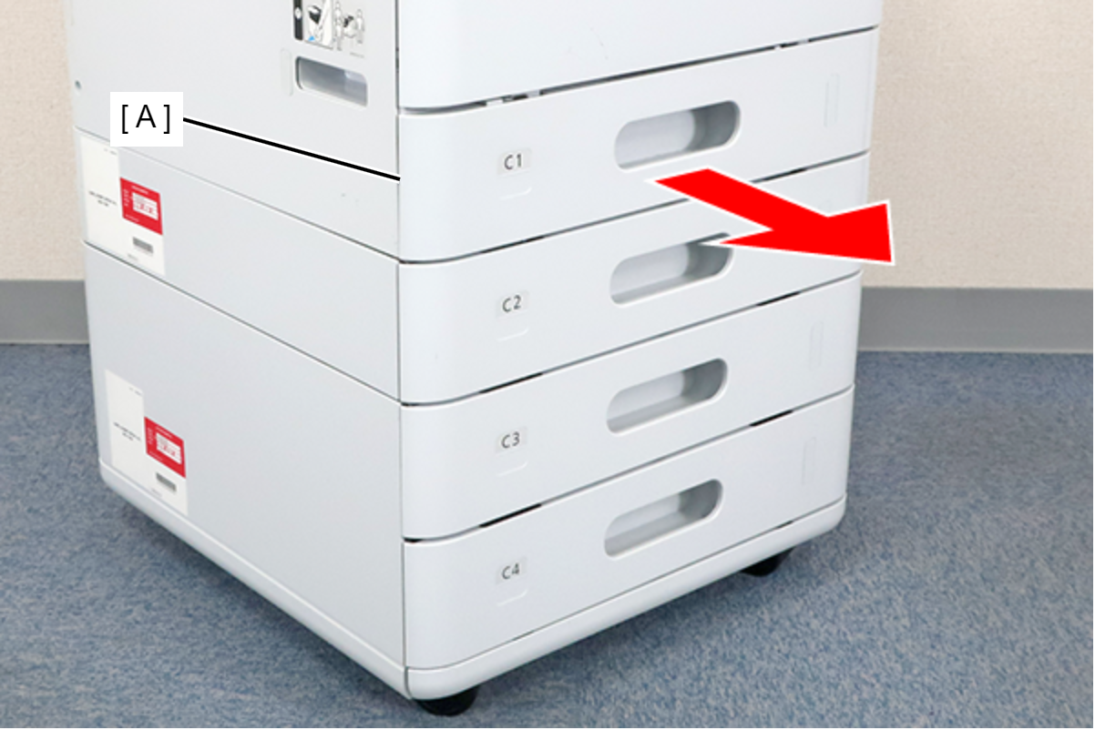
- Remove the C1 cassette (A).
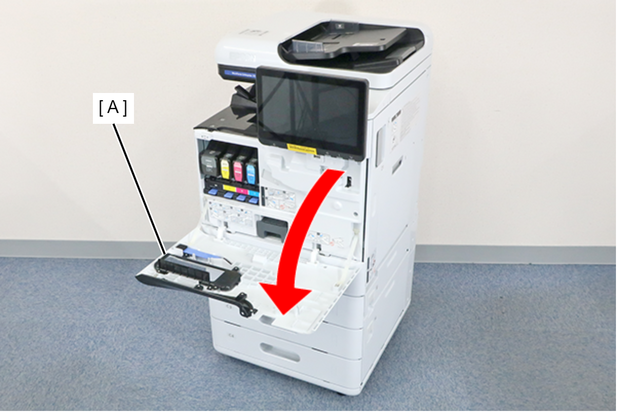
- Open the Front Cover (A).
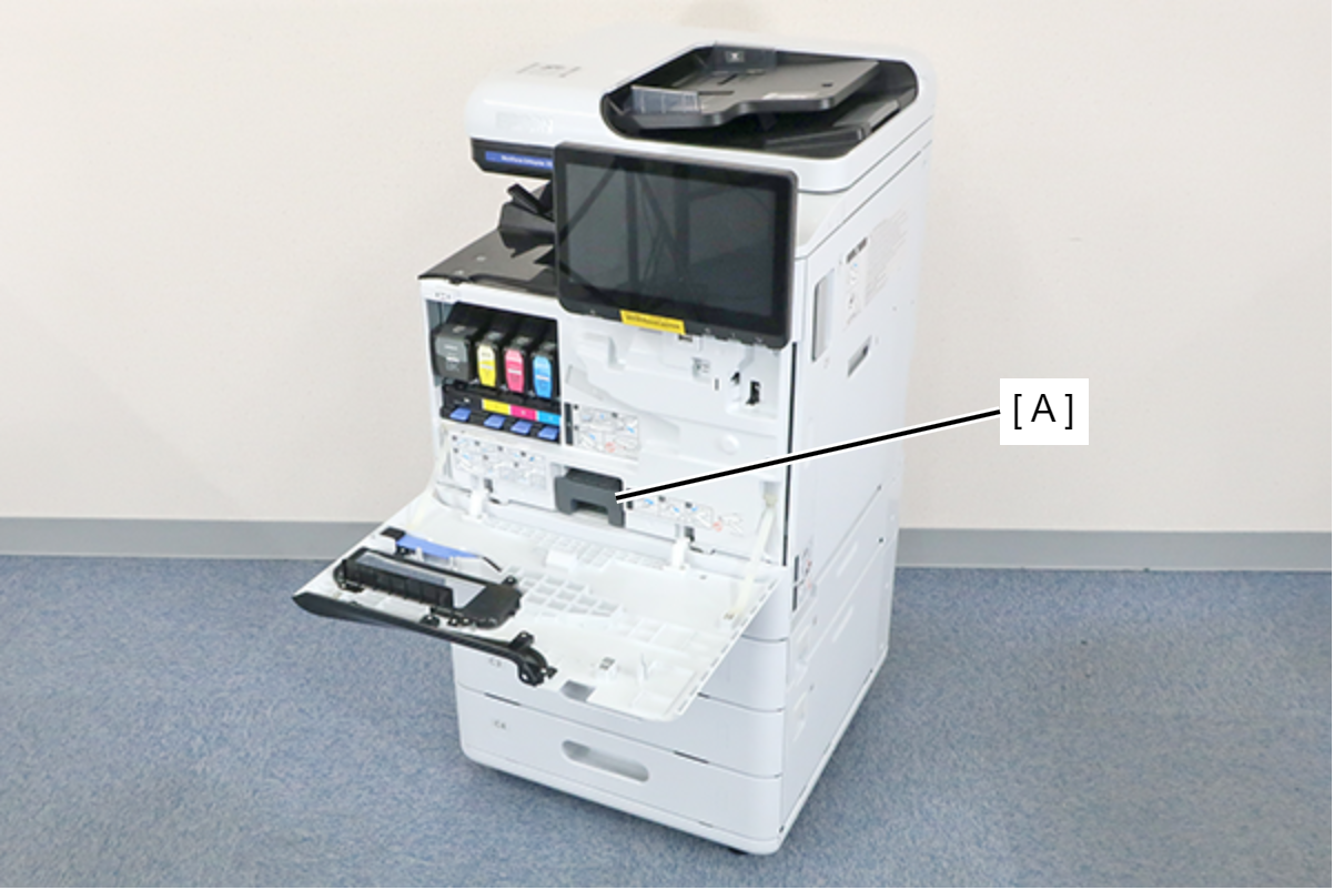
- Remove the Maintenance Box (A).
- Remove the 7 screws and remove the Front Inner Cover (A).
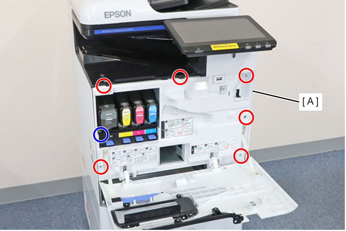
- : 3x8D
 : 3x8D/BK
Assembly / 組み立てInsert the protrusion (A) of the Front Inner Cover into the hole (B) of the main unit and install.
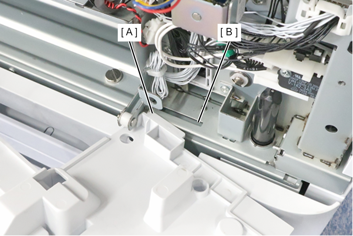
 Note / 補足
If the wireless LAN unit (A) is installed, remove it.

- Remove the 1 screw and remove the ACES sensor cover (A) of the ink system unit.
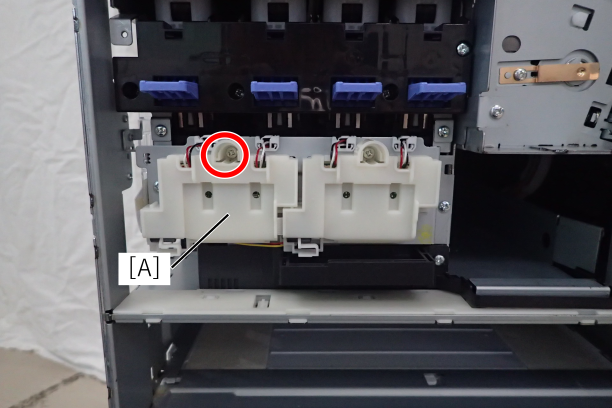
Remove the 4 ACES sensor cables (A) from the ink system unit.
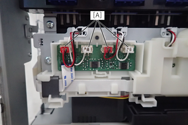
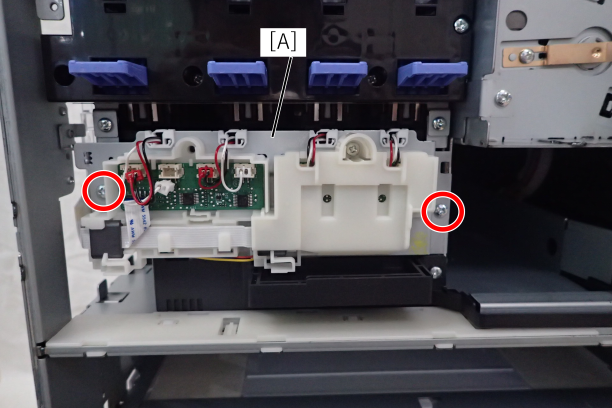
- Remove the 2 fixing screws from the ACES sensor board unit (A) of the ink system unit.
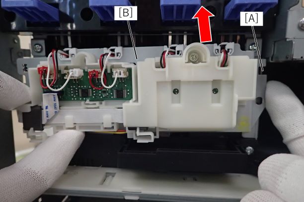
- Release the right hook (A) and lift up the ACES sensor board unit (A) of the ink system unit.
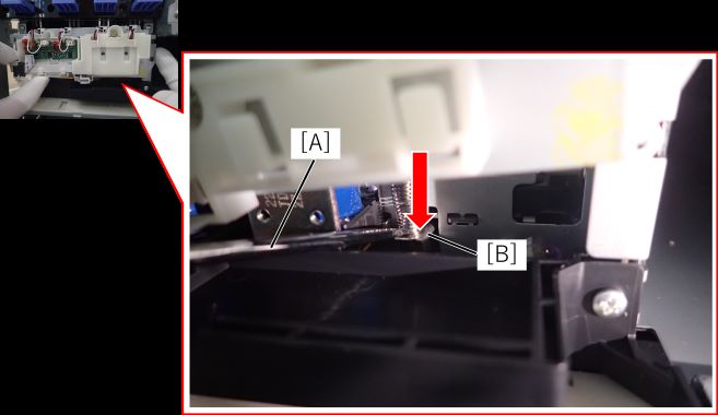
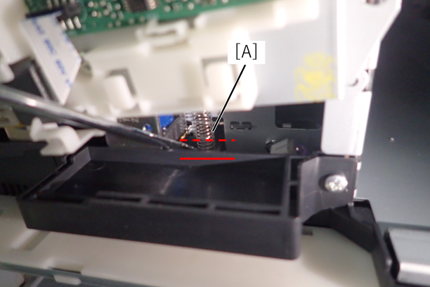
- Push down the solenoid plate of the flow path valve with a flathead screwdriver.
 important / 重要
Checking the valve opening/closing plate has moved from the red dashed line to the red line.
Flow path valve open
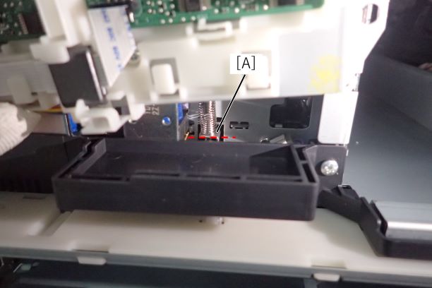
Flow path valve closed
 Check Point / チェックポイント Check Point / チェックポイント |
Head transportation part1 (A) should be transplanted to the replaced front inner cover.
|