
SCN Main Board Assy
 Check Point / チェックポイント Check Point / チェックポイント |
|
- Remove the 4 screws of the ADF Rear Cover (A).
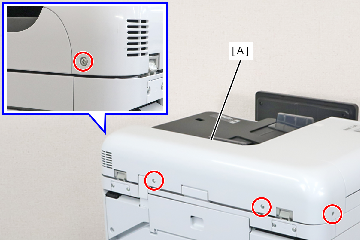
 : 3x8D
- Open the ADF (A).
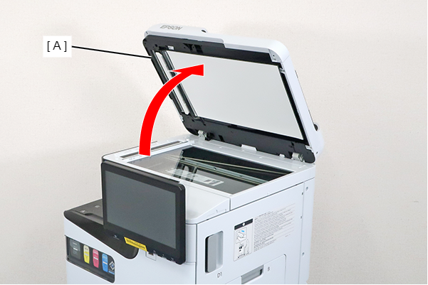
- Insert a tool with a narrow tip such as a flathead screwdriver from the position indicated by the ∧ mark (A) shown in the figure, and disengage the 2 hooks.
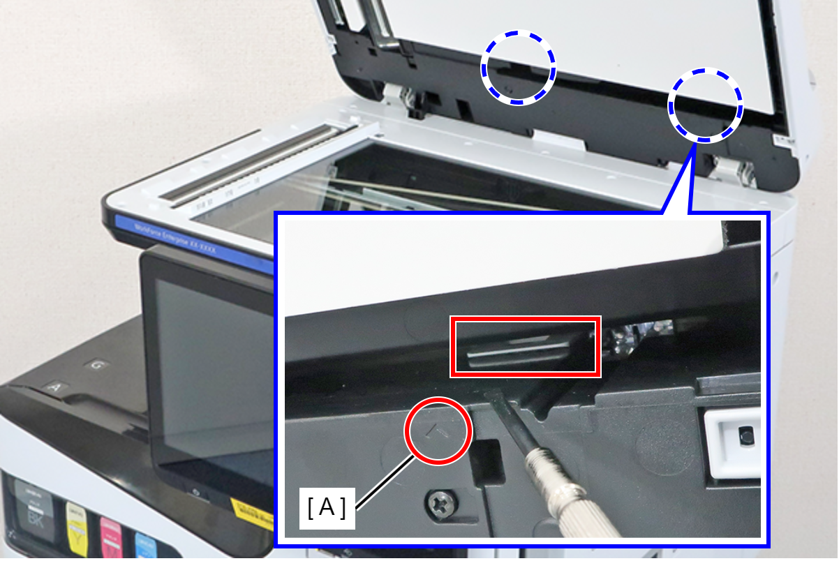
 Assembly / 組み立て
Align and attach the 2 hooks at the position indicated by the ∧ mark (A).
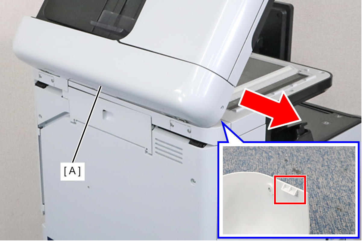
- Pull the ADF Rear Cover (A) out in the direction of the arrow to release the hook, and remove the ADF Rear Cover.
Disconnect the cables from the connectors (A) (CN400/CN604) of the SCN Main Board, and release the routing.
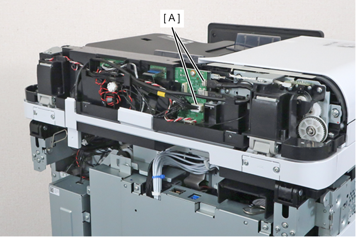 Assembly / 組み立て
See the following steps, and route the cables.
- While holding the cable holder (A), pull the cable (B) in the direction of the arrow, making sure that there is enough extra length to match the marking (C) on the cable with the bottom edge (D) of the cable holder.
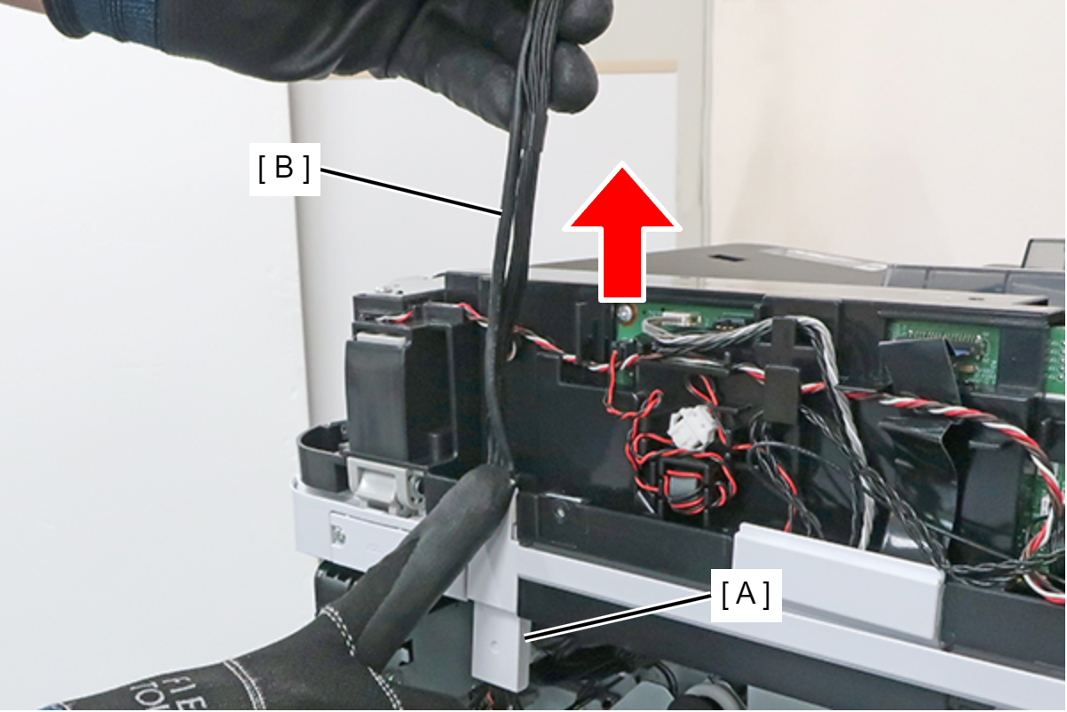
- Connect the 2 cables to the connectors (A) (CN400/CN604) on the SCN Board.
- Route the 2 cables through the 4 cable guides and align the 2 markings (B) with the rib edges (C).
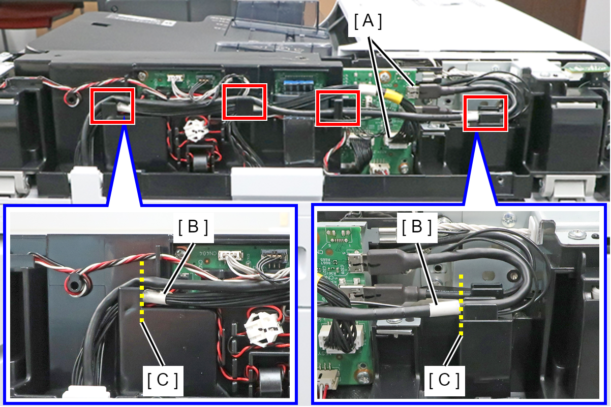
- While holding the cable holder (A), pull the cable (B) in the direction of the arrow, making sure that there is enough extra length to match the marking (C) on the cable with the bottom edge (D) of the cable holder.
- Disconnect the cables from the connector (A) (CN300) of the SCN Main Board, and disconnect the two grounding wires (B).
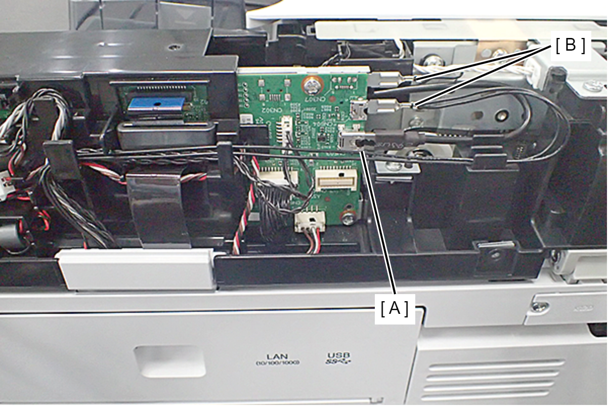 Assembly / 組み立て
Route the grounding wire (A) by hooking it on the 2 ribs.
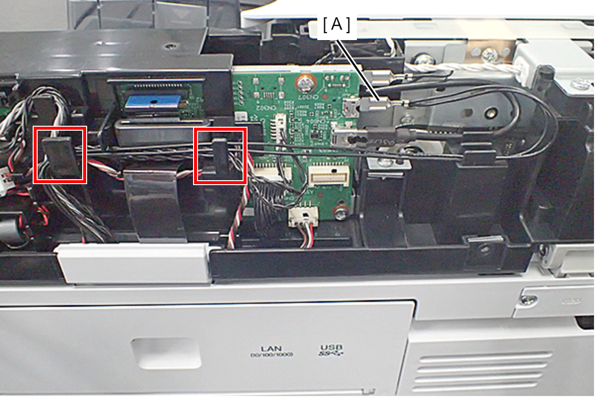
- Disconnect the cables from the connector (A) (CN403) of the SCN Main Board, and release the routing.
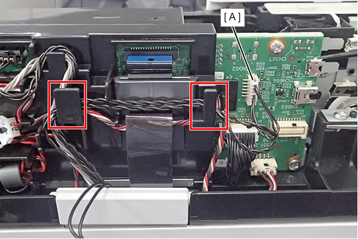 Assembly / 組み立て
Route the cables by hooking them on the 2 ribs.
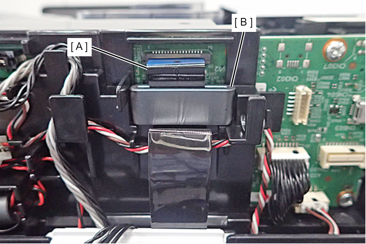
Disconnect the FFC (A) from the connector of the SCN Main Board, then disconnect the Ferrite Core (B).
 Caution / 注意
The connector is equipped with a connector lock, so make sure to release it before removing the FFC.
- Disconnect the cables from the connectors (A) (CN402/CN404) of the SCN Main Board, and release the routing.
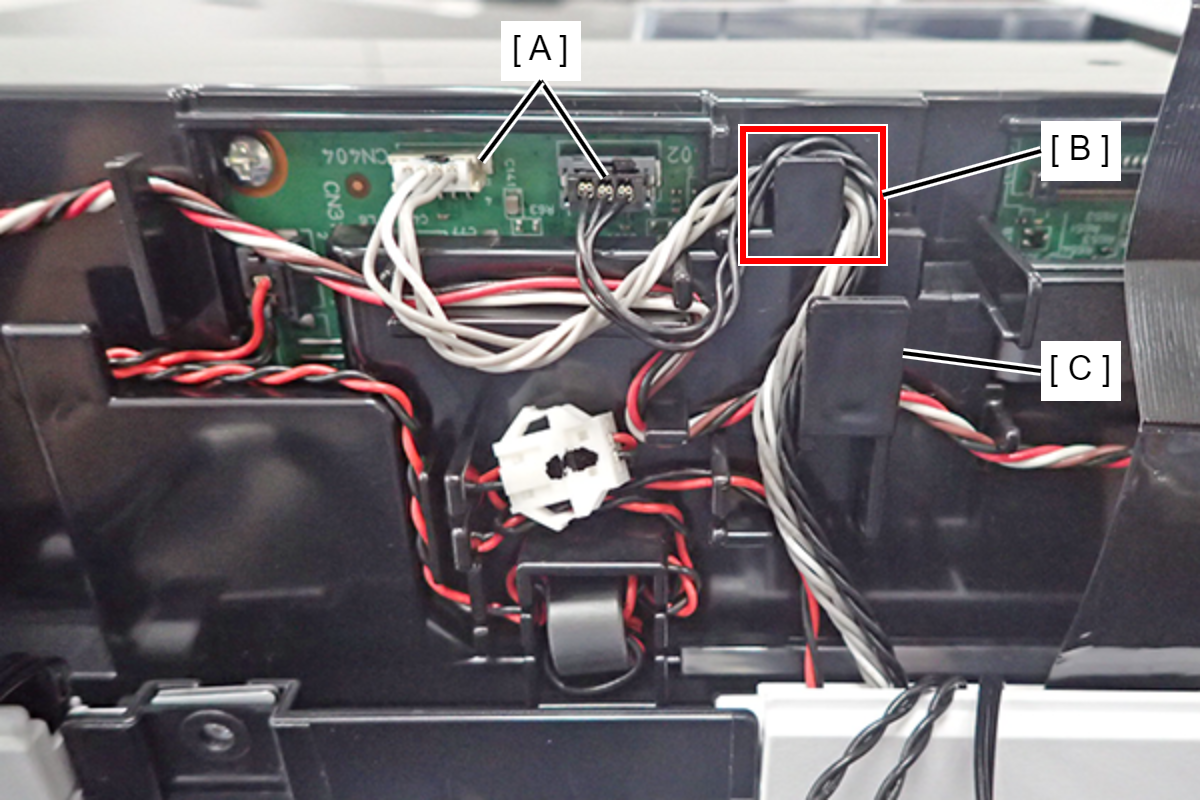 Assembly / 組み立て
Hook the cable on the rib (B) and then route it by passing it by the rib (C).
- Disconnect the cables from the connector (A) (CN601) of the SCN Main Board, and release the routing.
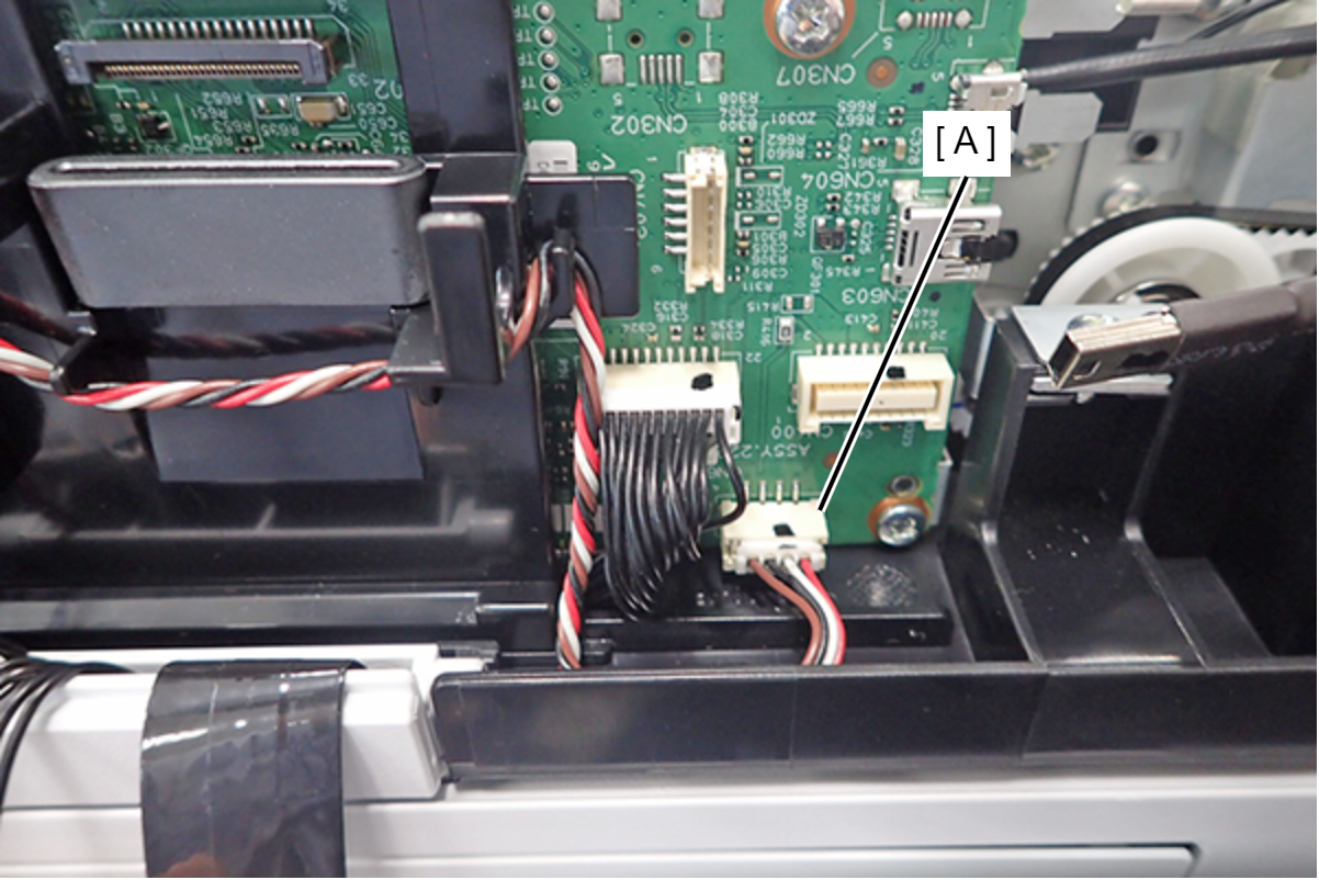 Assembly / 組み立て
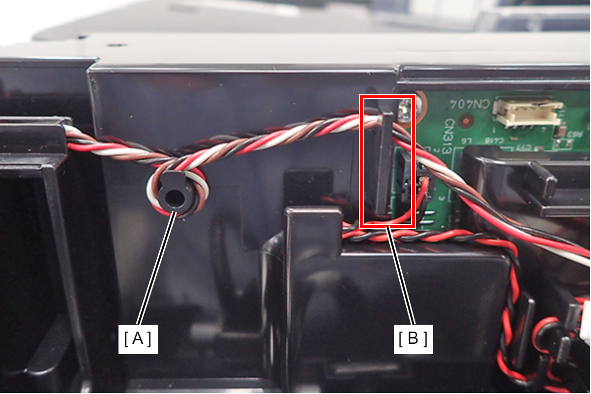
To route the cable (A), see the following steps.
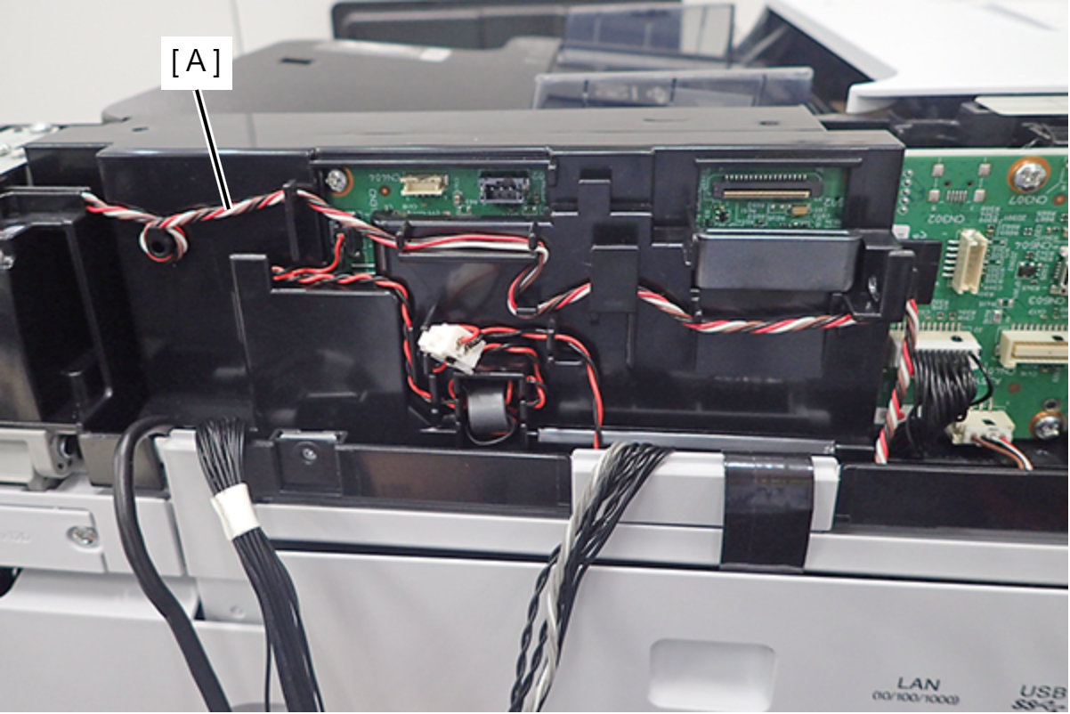
- Wrap it once around the shaft (A) and hook it on the rib (B).
- Hook it on the 3 ribs (A).
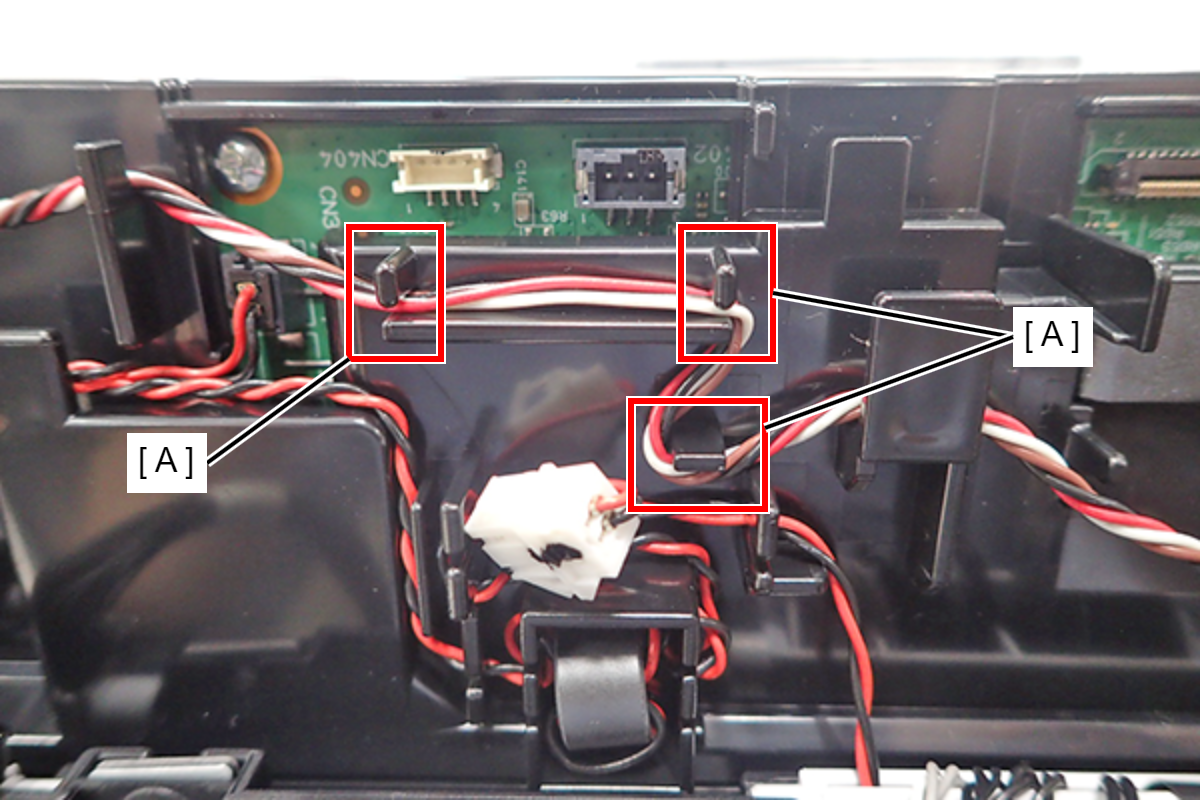
- Route it by hooking it on the 2 ribs (A).
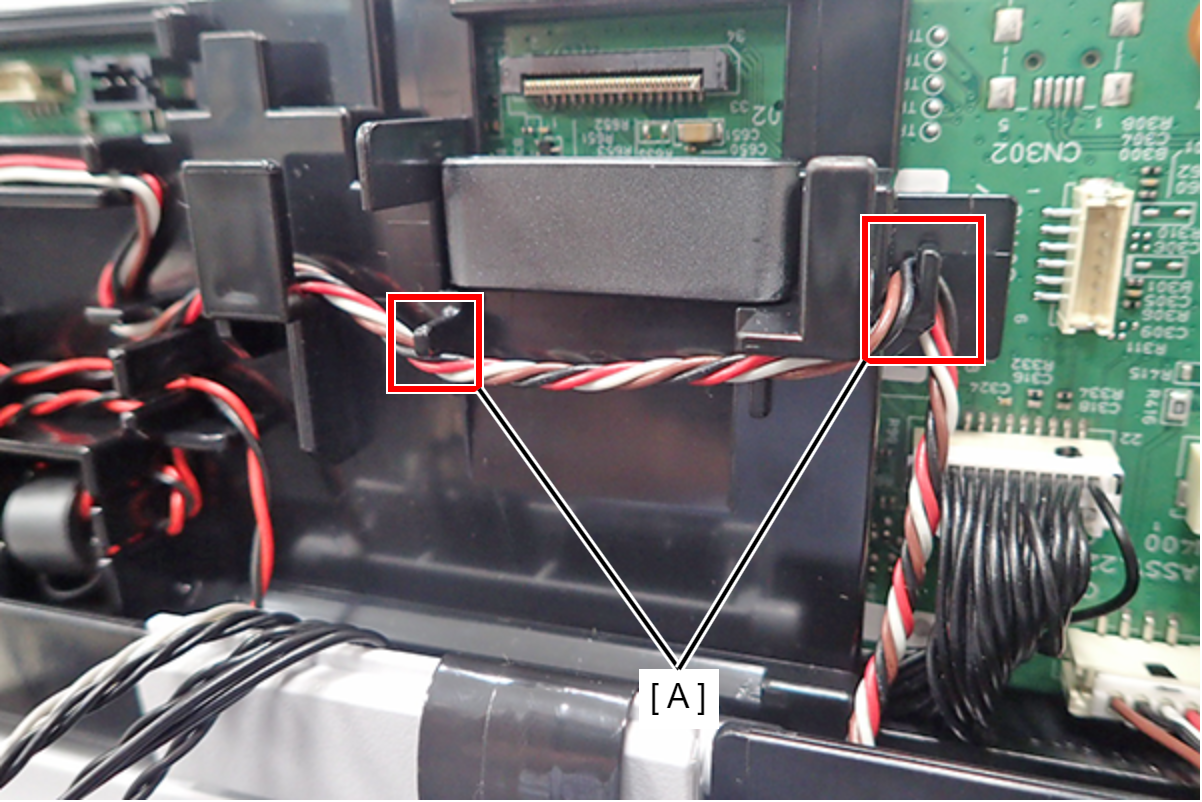
- Wrap it once around the shaft (A) and hook it on the rib (B).
- Disconnect the relay connector from the connector (A) (CN313) of the SCN Main Board, and disconnect relay connector (B).
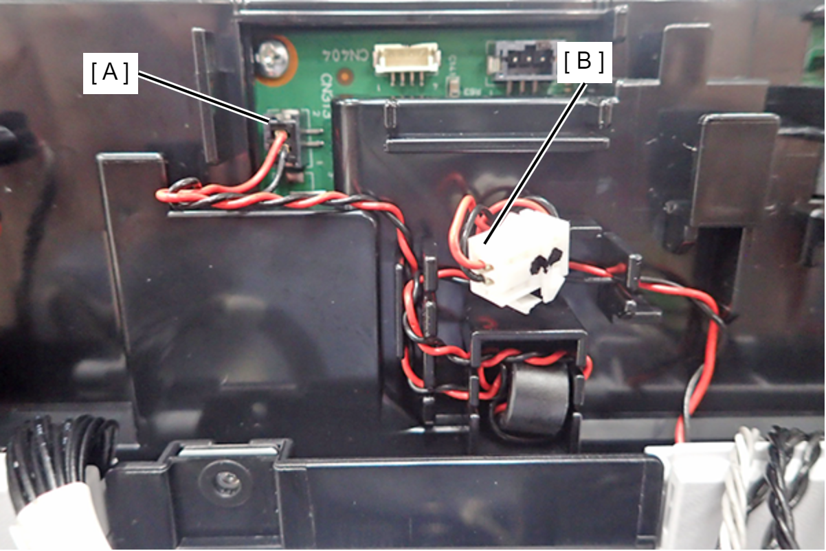
 Note / 補足
The ADF Main Board cover can be removed even when the relay cable (CN313) is routed, so there is no need to release it.
- Remove the 2 screws and remove the ADF Main Board Cover (A).
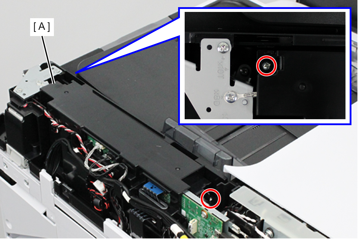
 : 3x8D
- Disconnect the cables from the connector (A) (CN300) of the SCN Main Board, and release the routing.
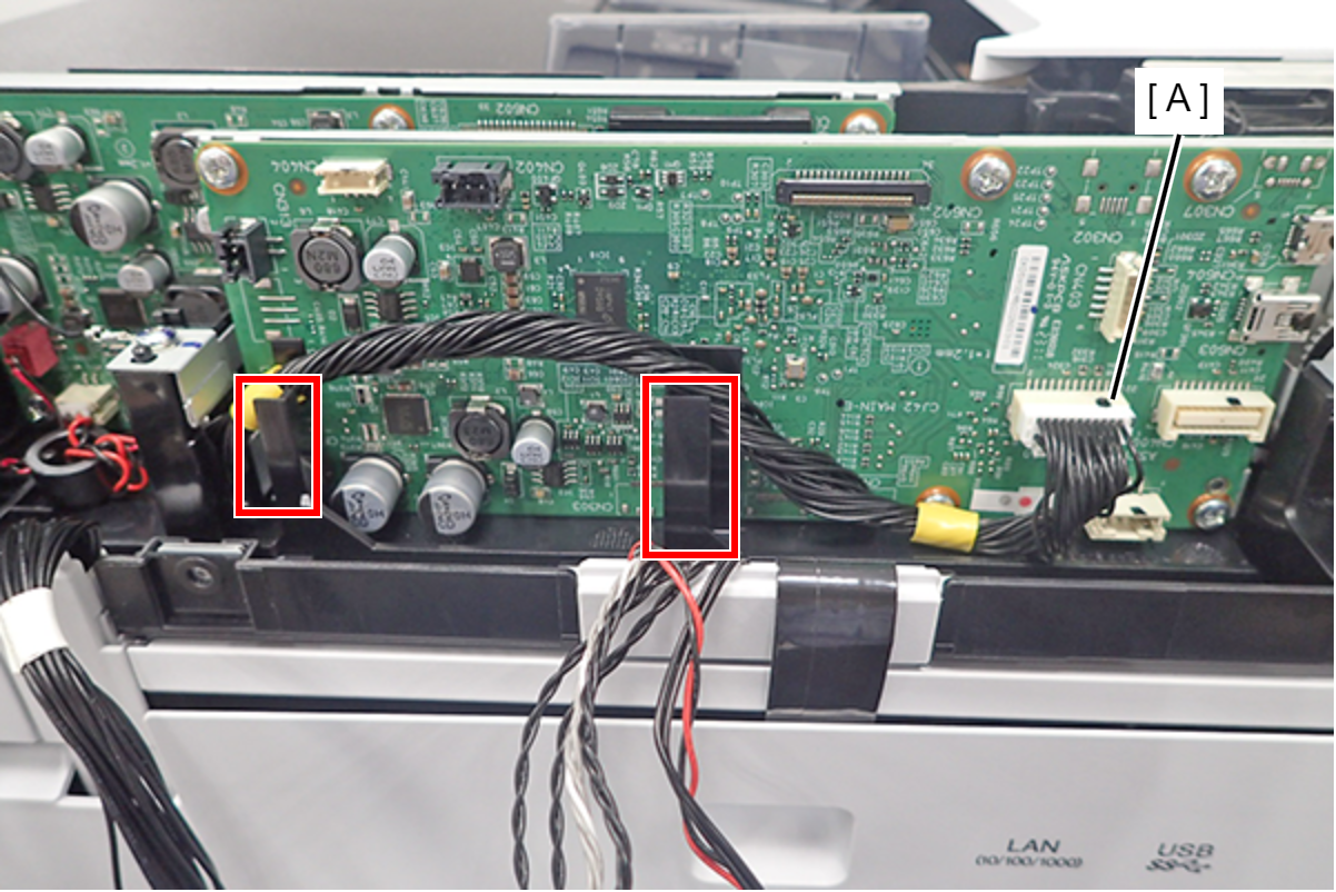 Assembly / 組み立て
Route the cables through the 2 ribs.
- Remove 2 screws, then remove the SCN Main Board Assy (A).
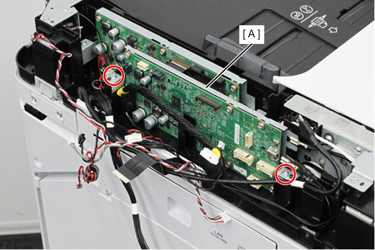
- : 3x8D
Assembly / 組み立てThe screw position shown in the figure must be fastened together with the ground wire (A).
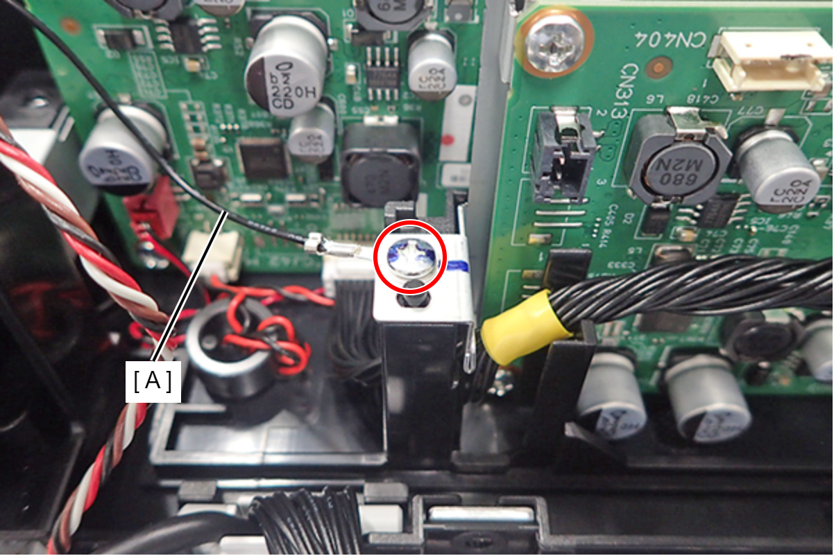
| Check Point / チェックポイント |
After replacing this part, you need to run the menu from the service support mode. (If you ran the Before-replacement menu before replacing the part, it will start automatically when you turn the power on.) |