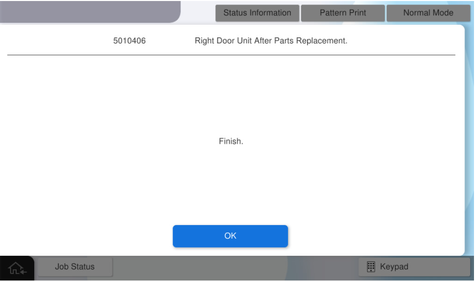
Right Door Unit - After Replacement
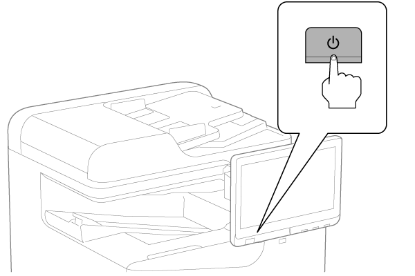
- Turn the power ON.
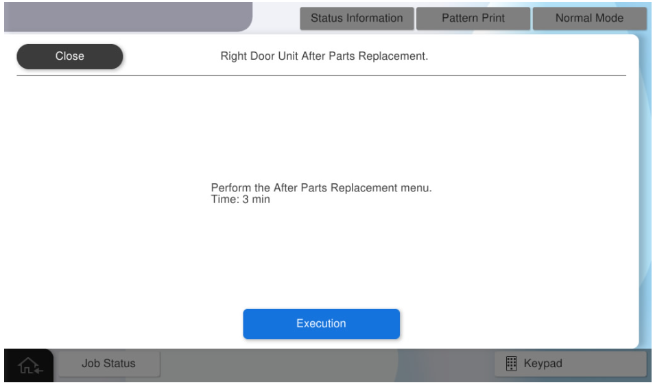
- Press [Execution].
- Press [OK].
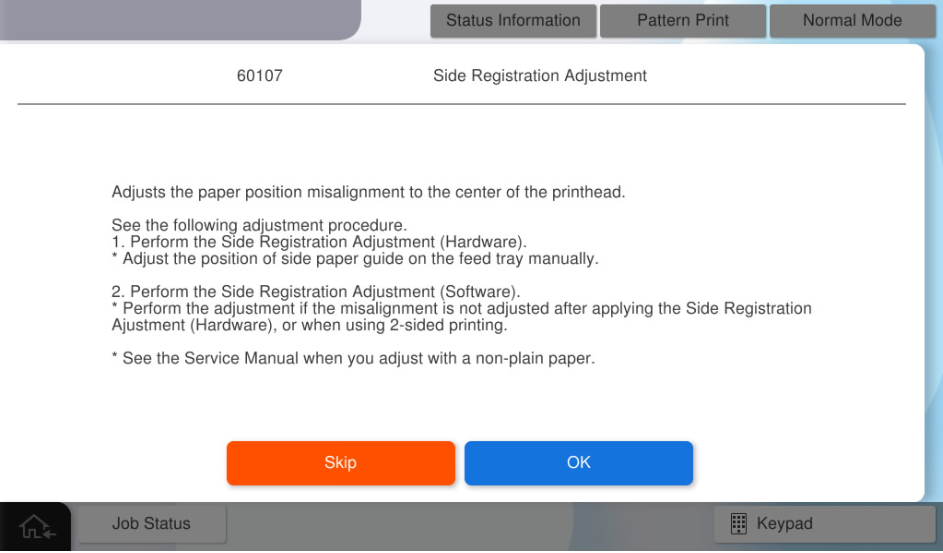
- Press [Pattern Print].
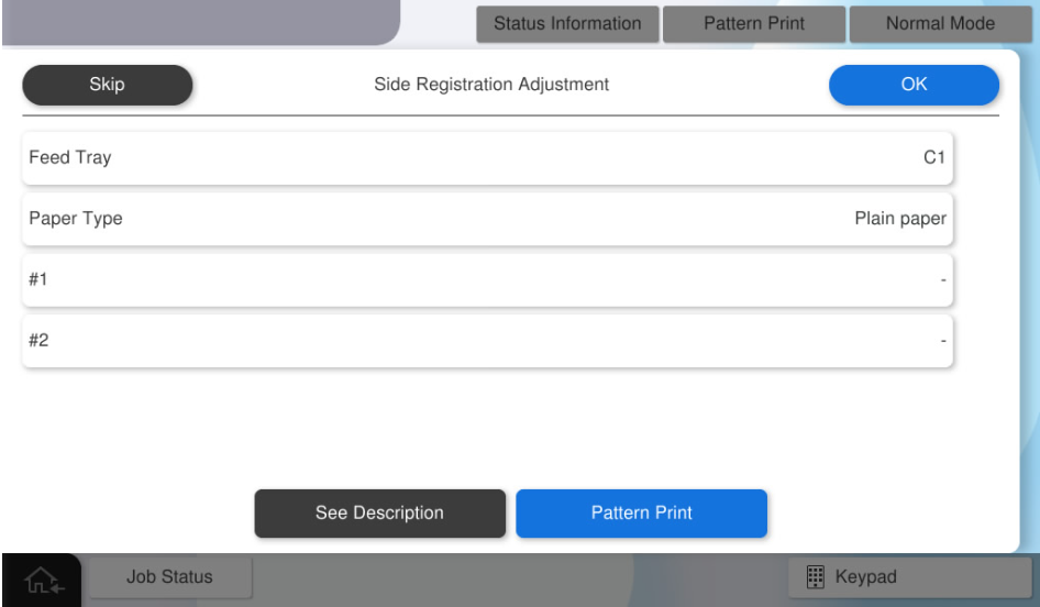
press each setting item button to make the print settings.
the parameters that can be set are as follows.
setting items choice feed tray c1, c2, c3, c4, Paper Tray available paper sizes a4, letter  Check Point / チェックポイント
match the paper feeder to be adjusted with the paper feed tray for pattern printing.
e.g.) perform the Paper Tray’s side registration adjustment . → press [paper tray] and select [Paper Tray].
- Press [Execution] to print the pattern.
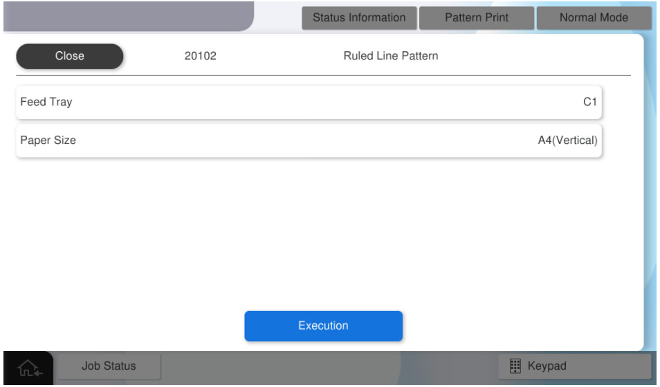
- perform hardware adjustment according to the following procedure.
scale the margin amount of # 1 and # 2 from adjustment pattern, and calculate the margin difference.
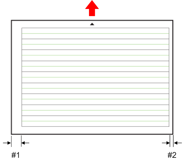
change the paper guide position for target paper feeder based on the margin difference. see how to change the paper guide below.
 Note / 補足
cassette unit (c1-c4)
- remove the target cassette unit.
- loosen 2 screws of the side paper guide at bottom of the cassette unit.
the paper guide position on the rear side of the product is changed based on the left and right margins of the adjustment pattern.
Check Point / チェックポイント- change the paper guide position using the adjustment scale as a guide.
- if you want to reduce the margin of #1: change to the rear side of the product.
- if you want to reduce the margin of #2: change to the front side of the product.
- the adjustment width is ± 3 mm, and the minimum adjustment unit is 1 mm.
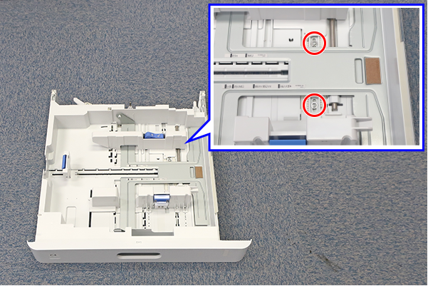
- change the paper guide position using the adjustment scale as a guide.
after changing the paper guide position, retighten the two screws loosened in step 2.
Paper Tray
- open the Paper Tray.
- loosen the screw at center of Paper Tray.
the paper guide position on the rear side of the product is changed based on the left and right margins of the adjustment pattern.
Check Point / チェックポイント- change the paper guide position using the adjustment scale as a guide.
- if you want to reduce the margin of #1: change to the front side of the product.
- if you want to reduce the margin of #2: change to the rear side of the product.
- the adjustment width is ± 3 mm, and the minimum adjustment unit is 1 mm.
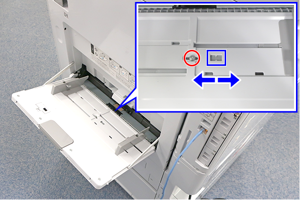
- change the paper guide position using the adjustment scale as a guide.
after changing the paper guide position, retighten the screws loosened in step 2.
output the adjustment pattern from the service support mode again, check the adjustment result.
Note / 補足- if the result is not satisfactory, repeat the hardware adjustment.
- if not improved, perform software adjustment.
Perform Software adjustment in the following procedure.
- Scale the margin amount of #1 and #2 from adjustment pattern.
- Distance from the paper edge to the "#1 mark"
- Distance from the paper edge to the "#2 mark"
- Convert the measured values into panel input values.
- Input value = measurement value x 10
- e.g.) Measurement value = 7.5mm, Input value = 75
- Press [Feed Tray] and select the feed tray to be adjusted.
- Press [Paper Type] and select the paper type to be adjusted.
- Press [#1] and enter the input value #1 calculated by step 2.
- Press [#2] and enter the input value #2 calculated by step 2.
Press [OK] to reflect setting value.
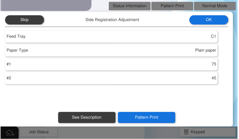 Check Point / チェックポイント
- If you press [OK] when all the values have not been entered, the following screen will be displayed.
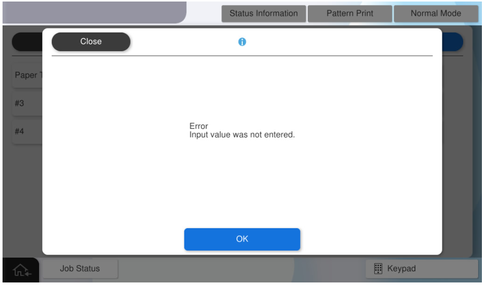
- If you press [Pattern Print] with all values entered, the adjustment values will be reflected. After the adjustment value is reflected, all the adjustment values input to the panel are cleared. Press [Skip] to end the adjustment.
By executing printing as it is, output the adjustment pattern after reflecting the adjustment values.
- If you press [OK] when all the values have not been entered, the following screen will be displayed.
- Scale the margin amount of #1 and #2 from adjustment pattern.
- Press [OK] to complete the menu.