
C3C4 Pickup Unit Connector Cover
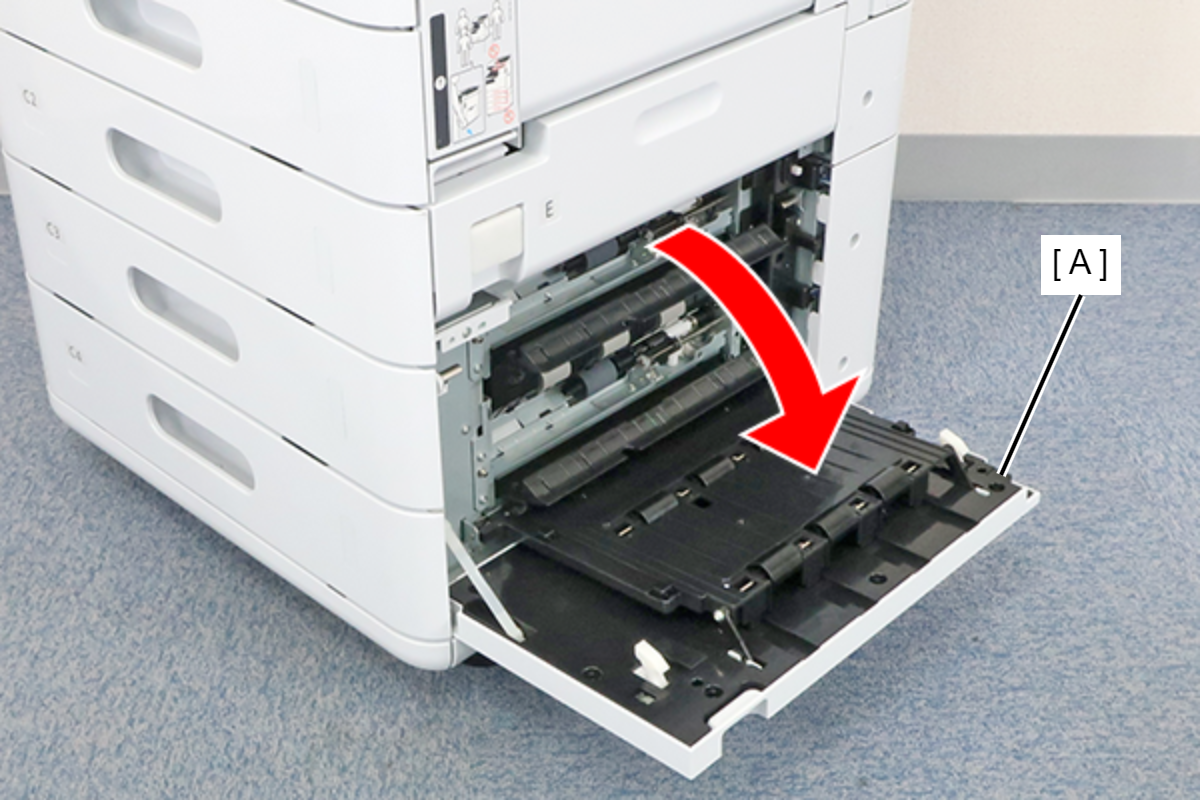
- Open the C3C4 Additional Paper Feed Cover (A).
- Remove the screw and remove the band (A).
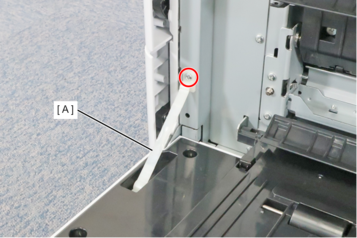
 : 3x8D
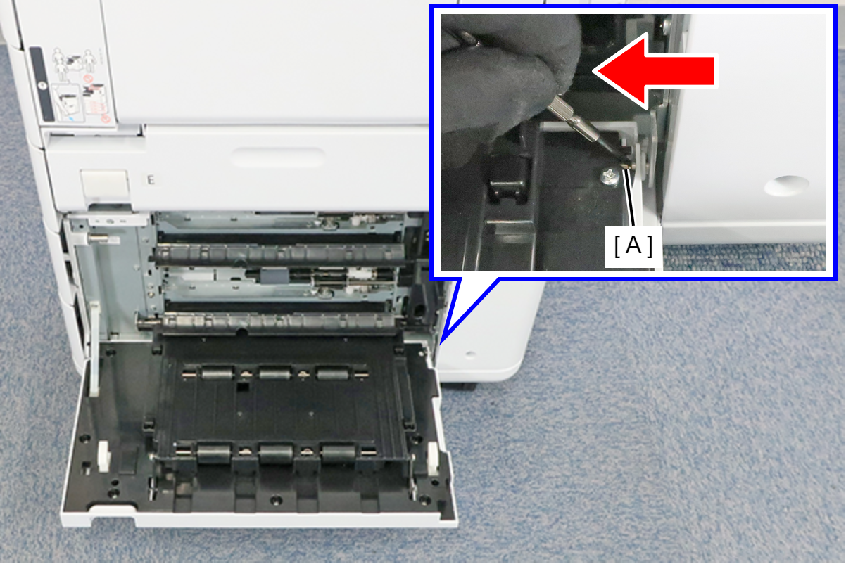
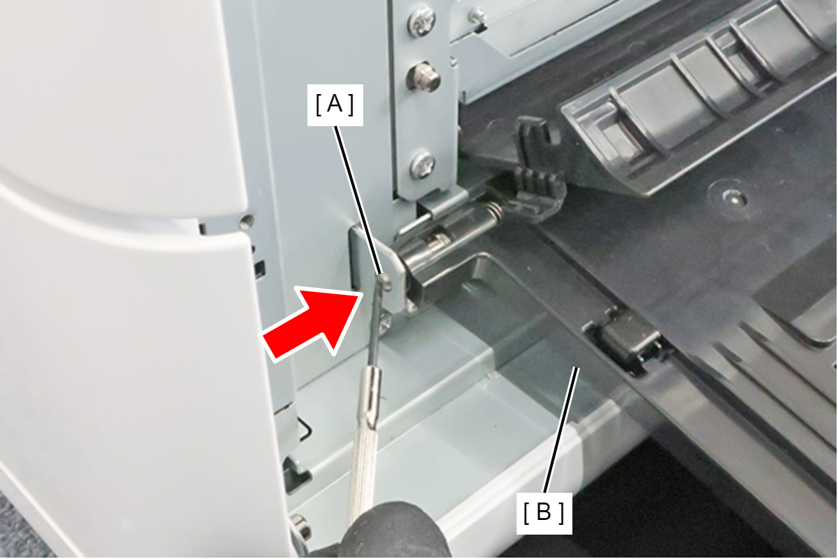
- Place a tool with a narrow tip such as a flathead screwdriver in the groove, and push it in the direction of the arrow to remove the shat (A) from the frame.
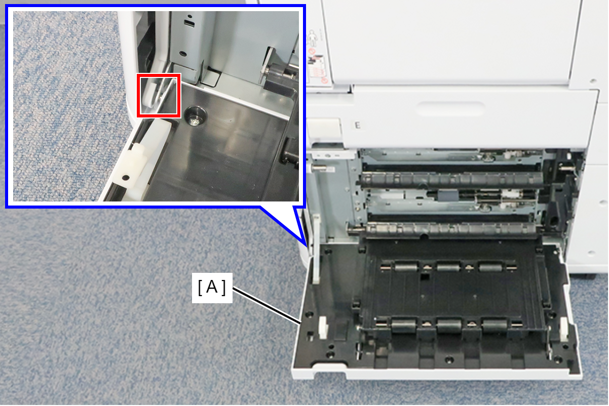
- Remove the C3 and C4 Additional Paper Feed Covers (A) from the opposite side shaft.
- Push the shaft (A) in the direction of the arrow to remove it from the frame, and remove the C3 and C4 Additional Paper Feed Covers (B).
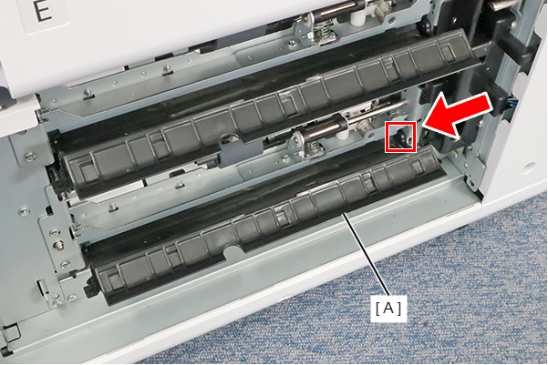
- Press the dowel in the direction of the arrow to release it, and remove the C4 Guide PF Inner (A).
- Remove the 4 screws fixing the C3C4 Additional Rear Cover (A).
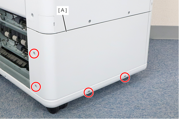
- : 3x8D
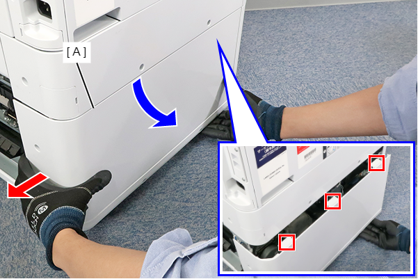
- While pulling the C3 and C4 Additional Rear Covers (A) out in the direction of the red arrow, rotate it in the direction of the blue arrow to disengage the 3 hooks, then remove the C3 and C4 Additional Rear Covers.
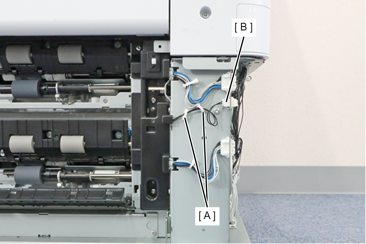
- Release the cable from the 2 clamps (A) and disconnect the cable from the relay connector (B).
- Remove the 3 screws and remove the C3C4 Pickup Unit Connector Cover (A).
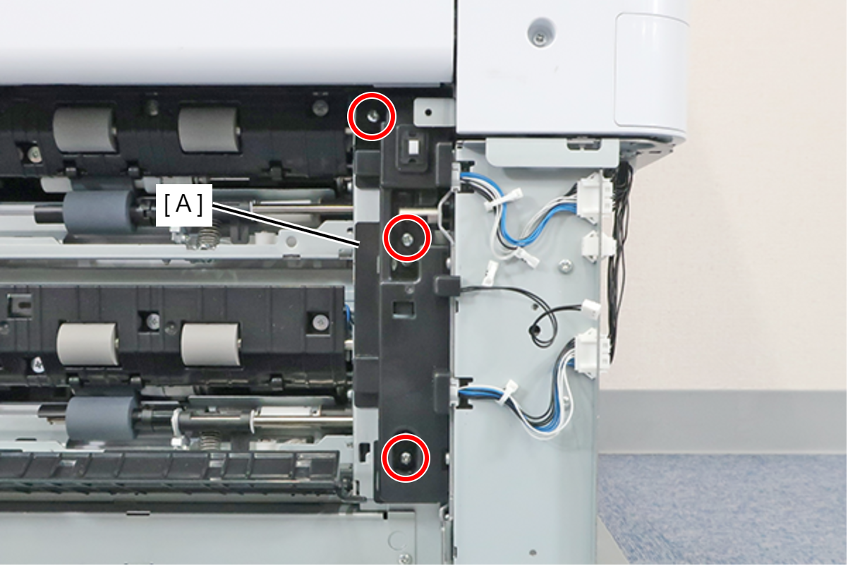
- : 3x8M