
Product Configuration (Part Names)
Front Right
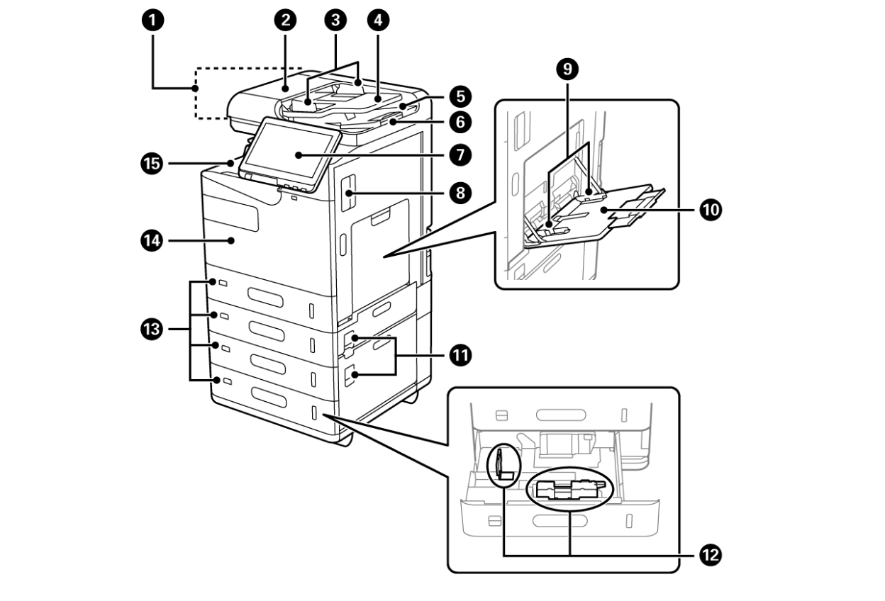
No. |
Part Name |
Description |
|---|---|---|
| 1 | ADF (Automatic Document Feeder) | Feeds originals automatically. |
| 2 | ADF Cover (F) | Open when removing jammed originals in the ADF. |
| 3 | ADF edge guide | Feeds originals straight into the printer. Slide to the edge of the originals. |
| 4 | ADF input tray | You can set multiple originals at once. |
| 5 | ADF output tray | Holds originals ejected from the ADF |
| 6 | Stopper | Prevents the ejected originals from falling from the ADF output tray. |
| 7 | Control panel | Allows you to make settings and perform operations on the printer. Also displays the printer’s status. |
| 8 | Cover (D1) | Open when removing jammed paper |
| 9 | Edge guide | Feeds the paper straight into the printer. Slide to the edges of the paper. |
| 10 | Paper tray (B) | Loads paper. You can load most paper available for this printer except for some of the paper. |
| 11 | Cover (E,H) | Open when removing jammed paper |
| 12 | Edge guide | Feeds the paper straight into the printer. Slide to the edges of the paper. |
| 13 | Paper cassettes 1, 2, 3, 4 (C1, C2, C3, C4) | Loads paper. C2, C3 and C4 are optional. |
| 14 | Front cover (A) | Open when replacing the ink cartridge or the maintenance box. You can also padlock the cover to prevent theft. |
| 15 | Tray (G) | Stores received paper. |
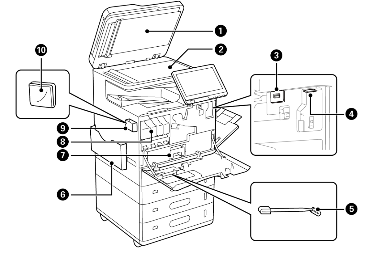
No. |
Part Name |
Description |
|---|---|---|
| 1 | Document cover | Blocks external light while scanning. |
| 2 | Scanner glass | Place the originals. You can place originals that are not fed from the ADF such as envelopes or thick books. |
| 3 | External interface USB port | Connect memory devices. |
| 4 | Wi-Fi unit port | Install the optional Wireless LAN Interface-P1 to connect to Wi-Fi. |
| 5 | Cleaning stick | This is a part for cleaning inside of the printer. |
| 6 | Manual holder | Holds the manuals. |
| 7 | Maintenance box | Collects waste ink discharged during cleaning and printing. |
| 8 | Ink cartridge | Install all four ink cartridges for four colors. |
| 9 | Cleaning cloth holder | Holds the cleaning cloth. |
| 10 | Cleaning cloth | Use to clean the glass surface of the scanner unit and the ADF. |
Rear
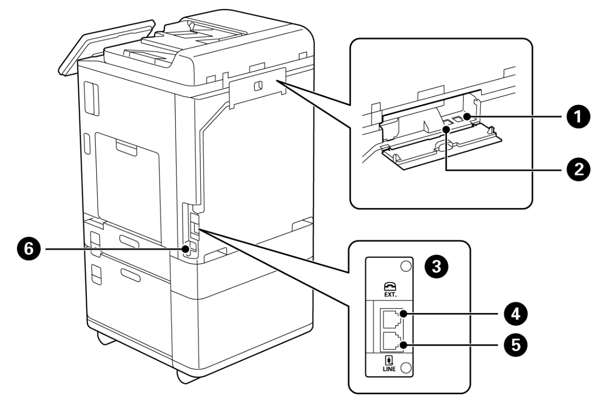
No. |
Part Name |
Description |
|---|---|---|
| 1 | USB port | Connects a USB cable. |
| 2 | LAN port | Connect LAN cables. |
| 3 | Additional interface slot | Install the Super G3/G3 Multi Fax Board. |
| 4 | EXT. port | Connects external phone devices. |
| 5 | LINE port | Connects a phone line. |
| 6 | AC inlet | Connects the power cord. |
Option Units
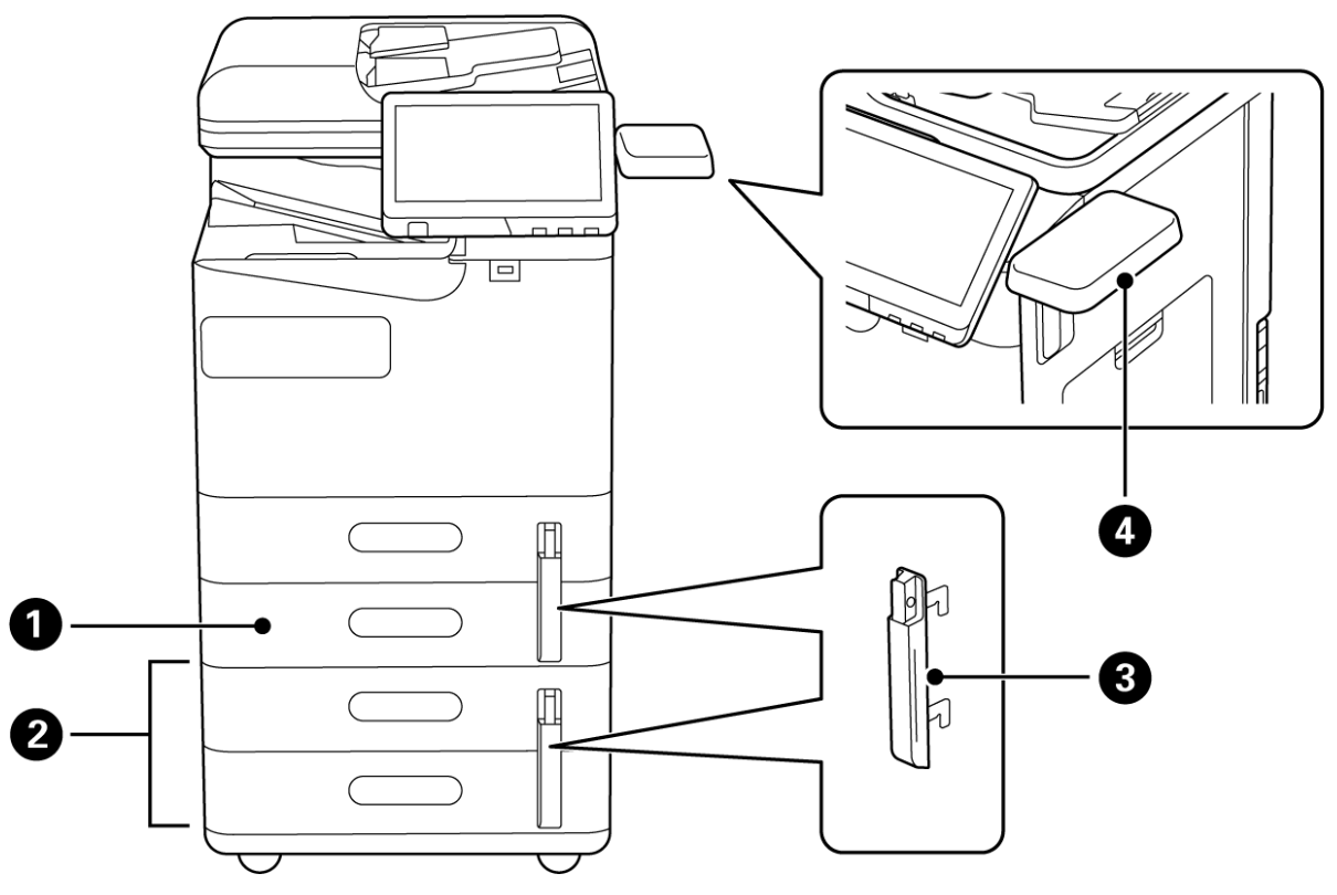
No. |
Part Name |
Description |
|---|---|---|
| 1 | Paper Cassette Unit (Single)-P1 | Adds paper cassette C2 to the printer. |
| 2 | Paper Cassette Unit (Dual)-P2 | Adds paper cassettes C3 and C4 to the printer. |
| 3 | Paper Cassette Lock-P1 | When the administrator wants to manage paper usage, attach this to two paper cassettes with a padlock to lock the cassettes. |
| 4 | Authentication Device Table- P1 | Allows you to attach an authentication device supported by the printer. You can then log on to the printer by holding an authentication card over the printer. |