
Anti Static Brush
 Check Point / チェックポイント Check Point / チェックポイント |
When replacing this part, you need to run the menu from the service support mode before replacing it. |
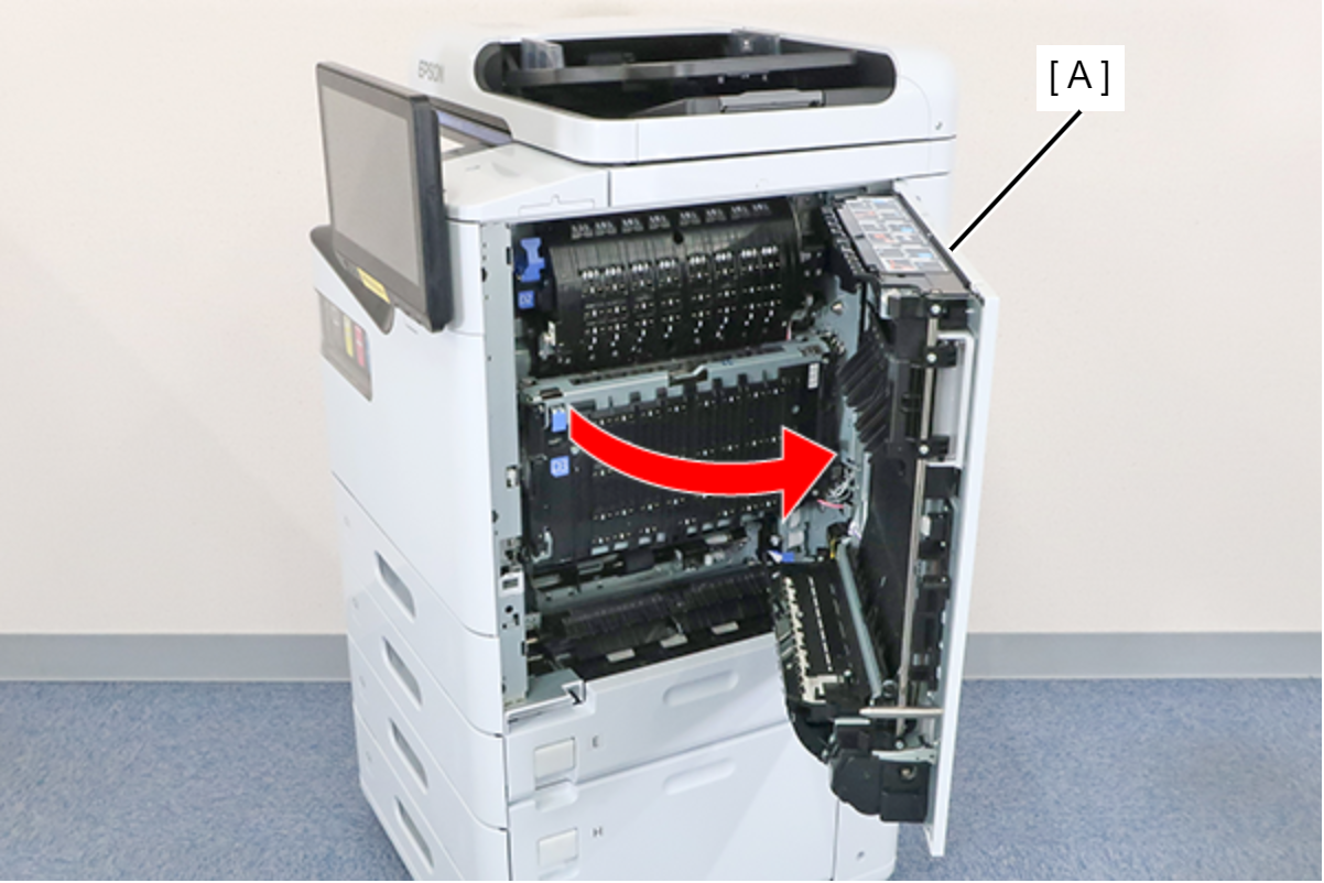
- Open the right door unit (A).
 Assembly / 組み立て
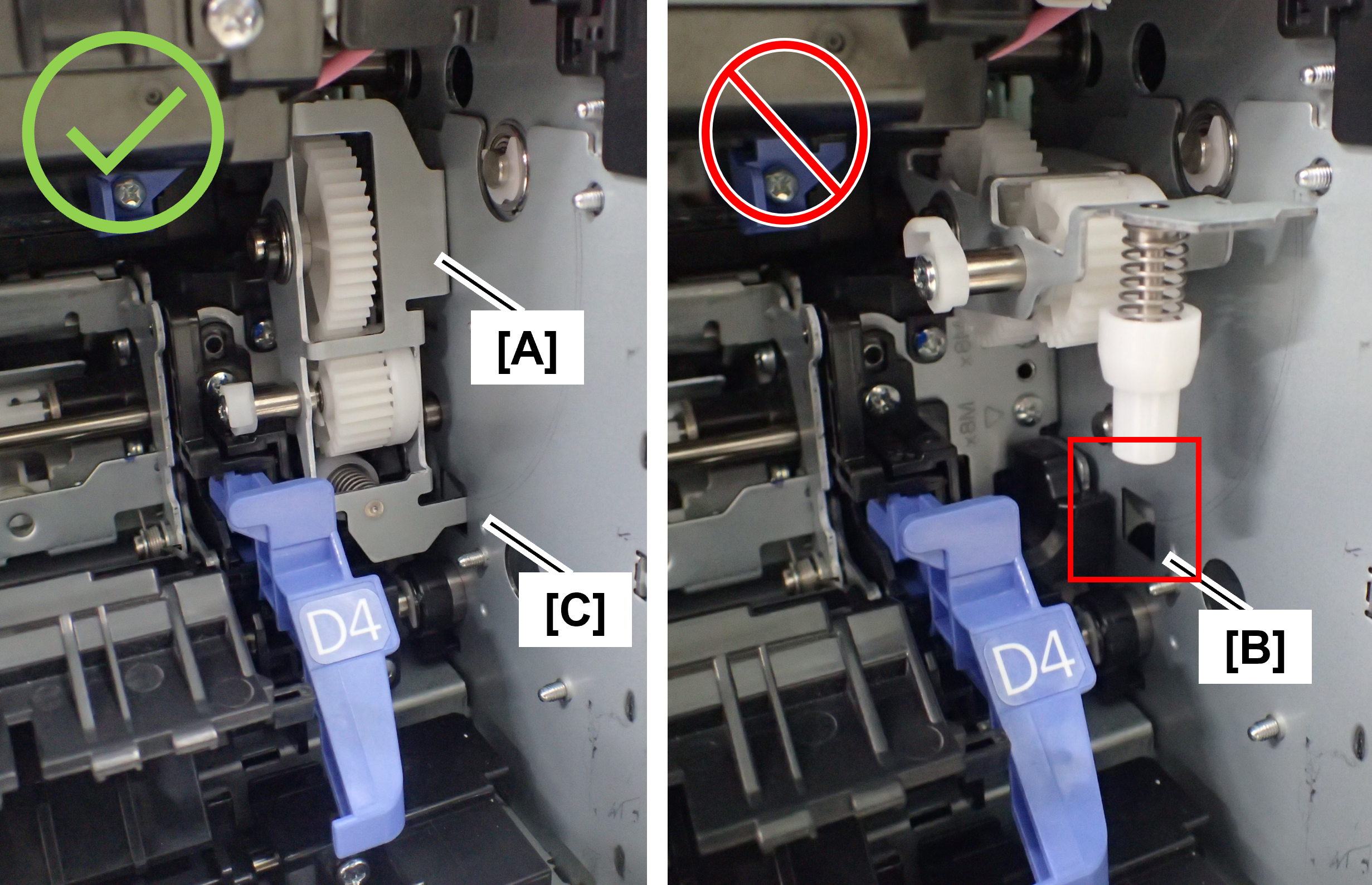
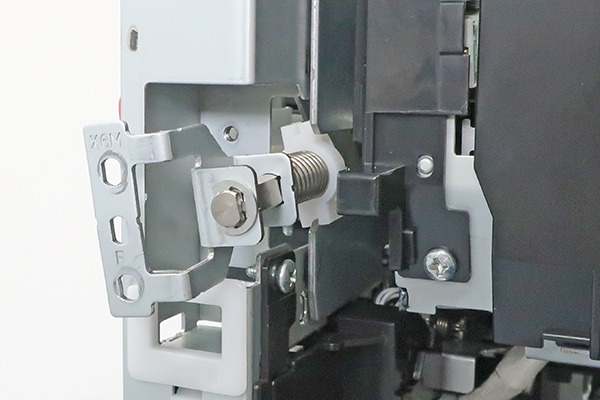
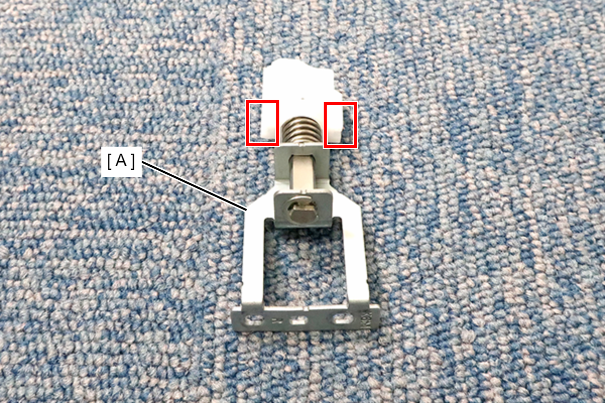
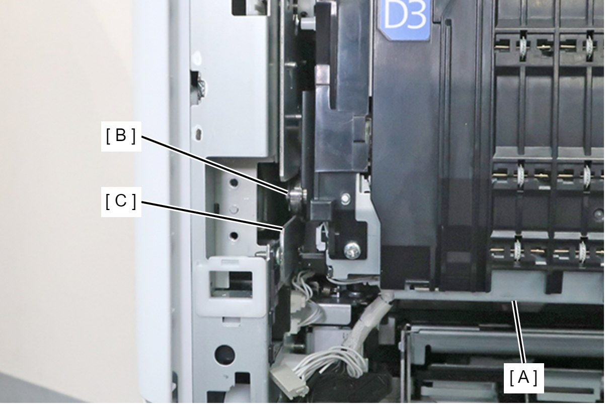
When closing the right door unit, it may not close due to interference with the tumbler (A) that was tilted toward the front when other parts were repaired.
If the right door unit does not close, check the position of the tumbler, and if it is protruding toward the front, fit the tip of the tumbler plate (C) into the hole (B) in the main unit.
- Remove the 2 screws and remove the Belt Attached Component Front (A).
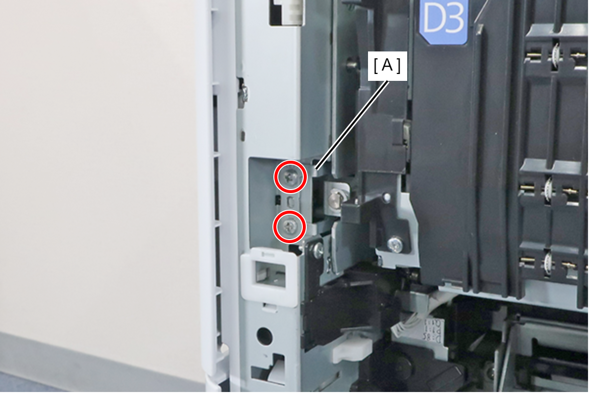
 : 3x6M
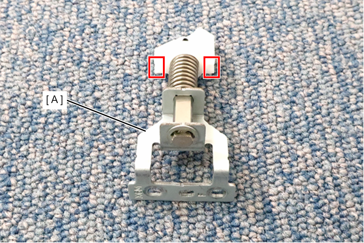
Assembly / 組み立てFit the body frames plates (B) into the two grooves of the Belt Attached Component Front (A).
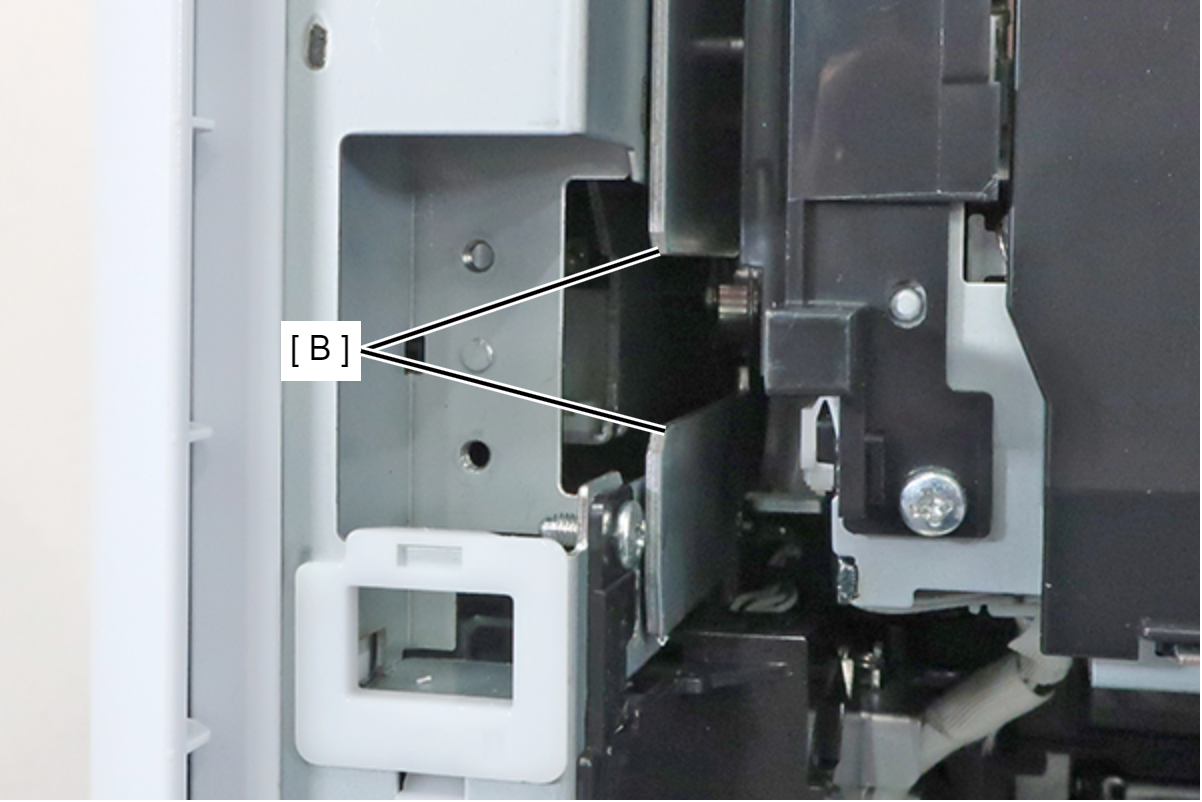
OK
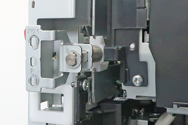
NG
- Remove 1 screw and remove the connector cover belt front (A) by sliding it toward you.
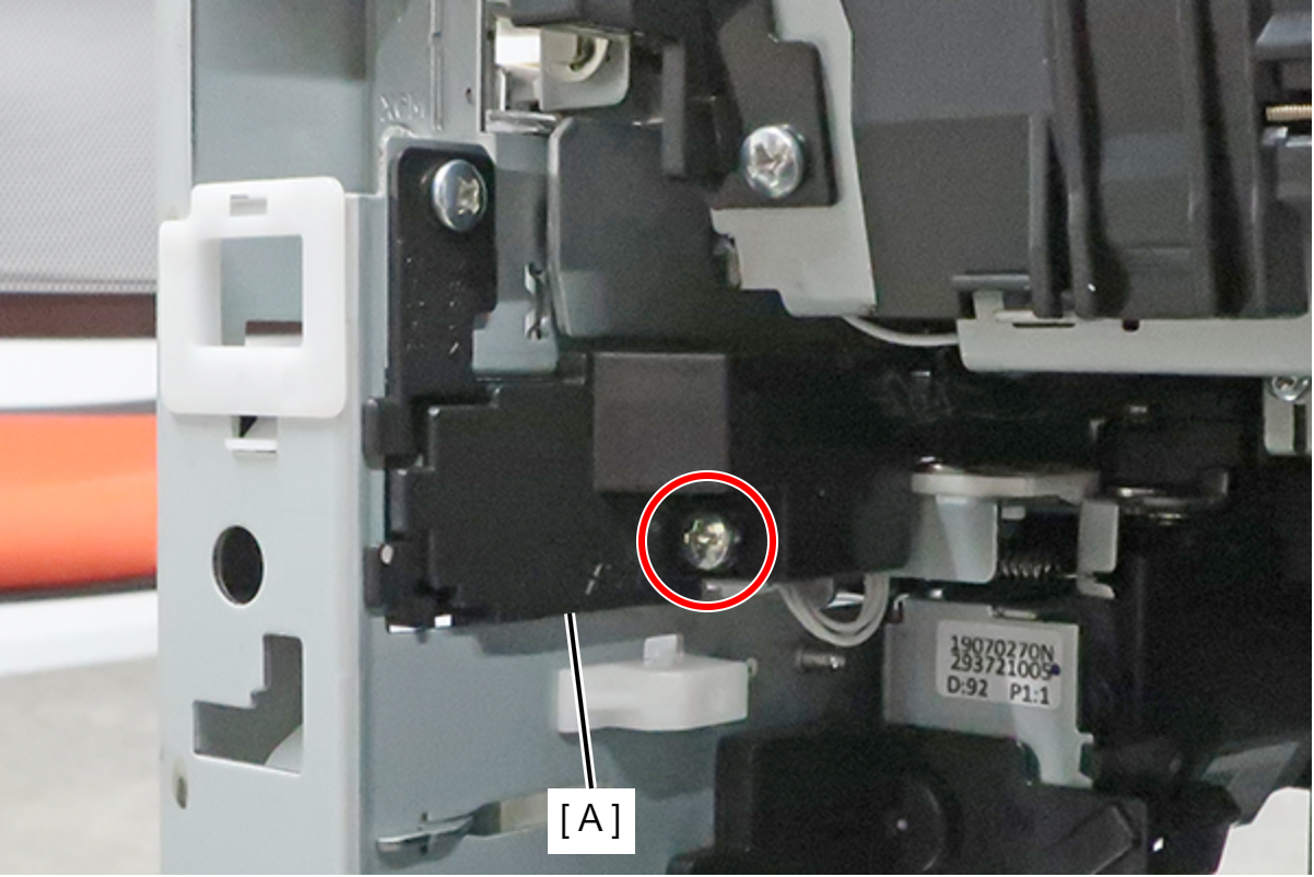
- : 3x8D
- Disconnect the cables from the 2 connectors (A).
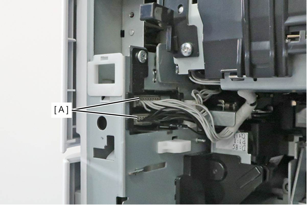
- Remove the screw fixing the Connector Cover Belt Rear (A).
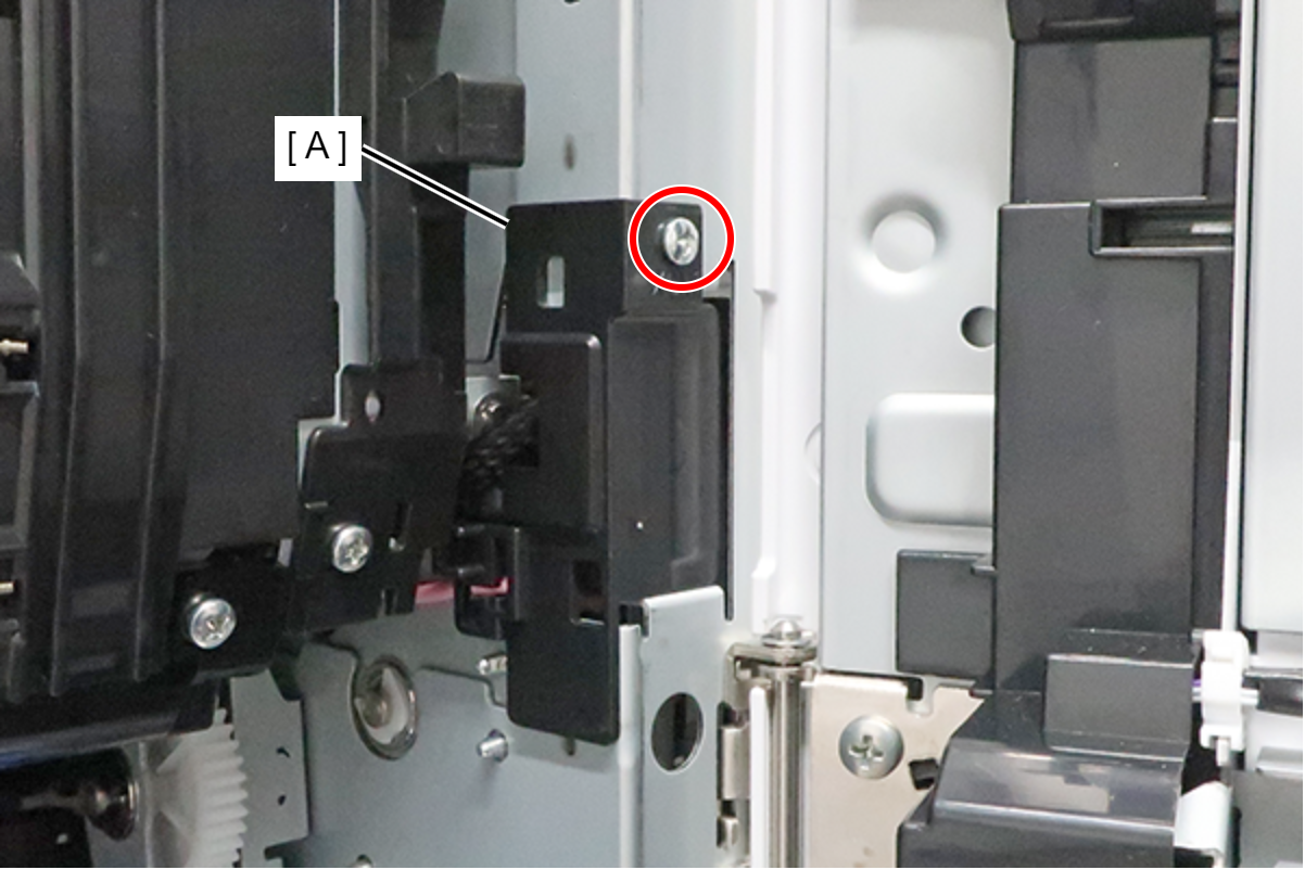
- : 3x6M
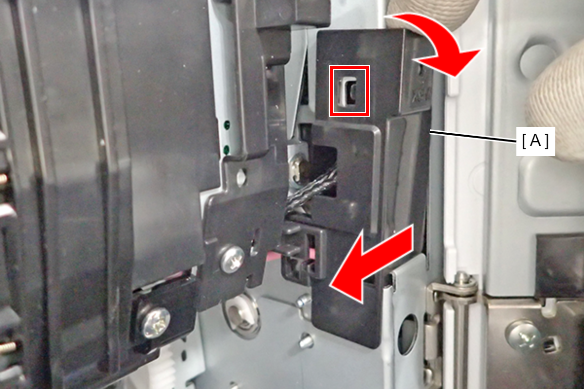
- Tilt the Connector Cover Belt Rear (A) toward you and then slightly slide it to the left to disengage the upper hook.
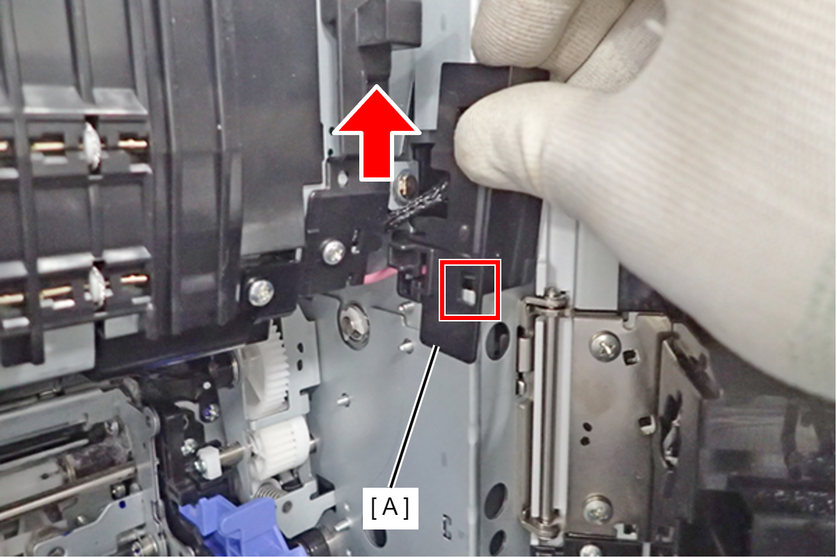
- Slide the Connector Cover Belt Rear (A) upward to disengage the lower hook, and remove it.
 Assembly / 組み立て
Follow the steps below to install the Connector Cover Belt Rear. Be careful not to let the high-voltage cable get caught between the cover and other components.
- Pass the high-voltage cable (B) through the cutout of Connector Cover Belt Rear (A) as shown below, and then insert the lower hook of the cover.
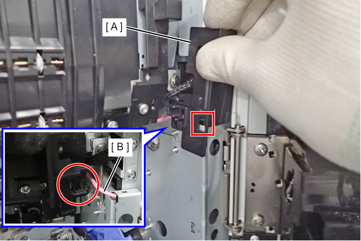
- Engage the upper hook with the hole, and attach the Connector Cover Belt Rear (A).
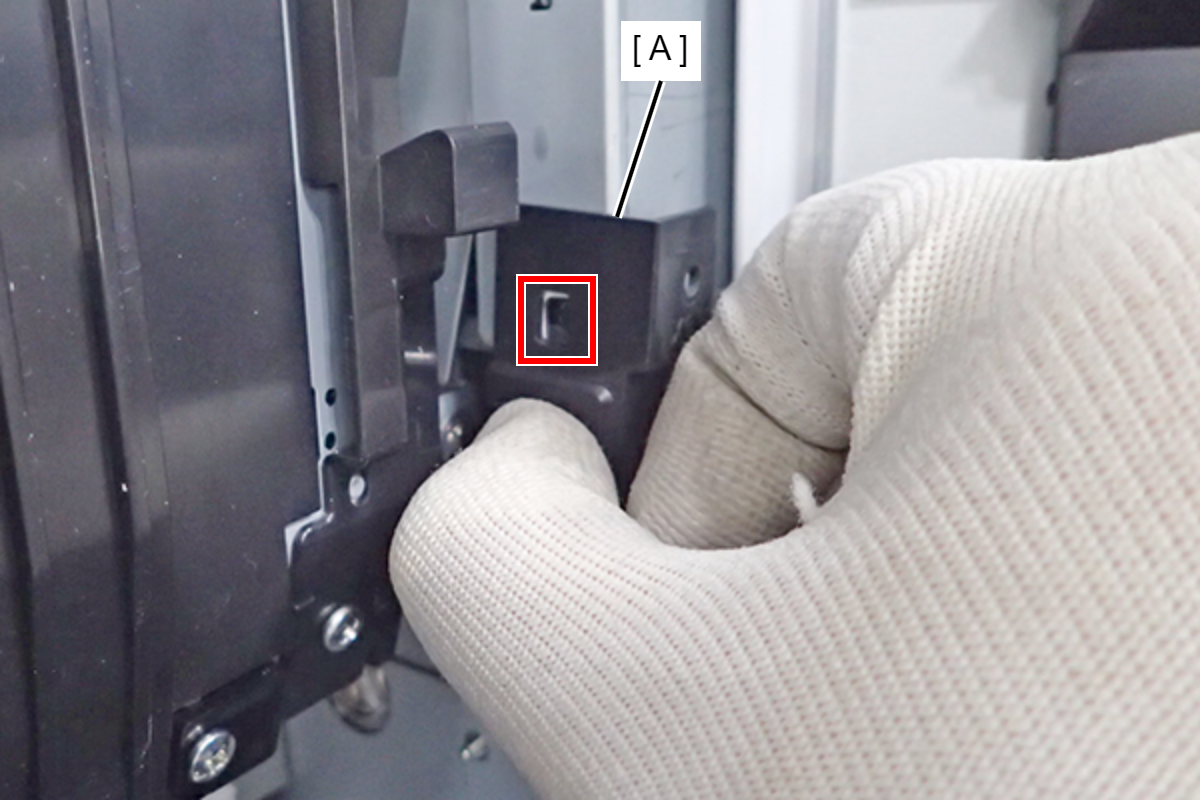
- Make sure that it is installed properly.
- OK
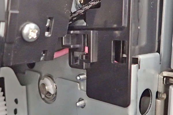
- NG
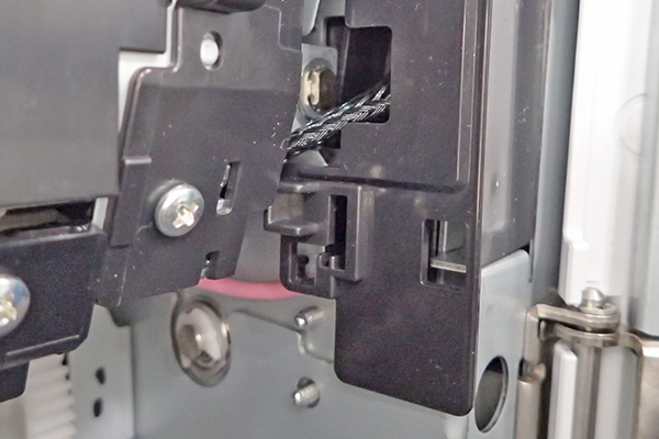
- OK
- Check that the high-voltage cable (A) is not stuck in between the cover and components by moving the cable.
If the high-voltage cable does not move, it is stuck in between them, so remove and reinstall the Connector Cover Belt Rear (B).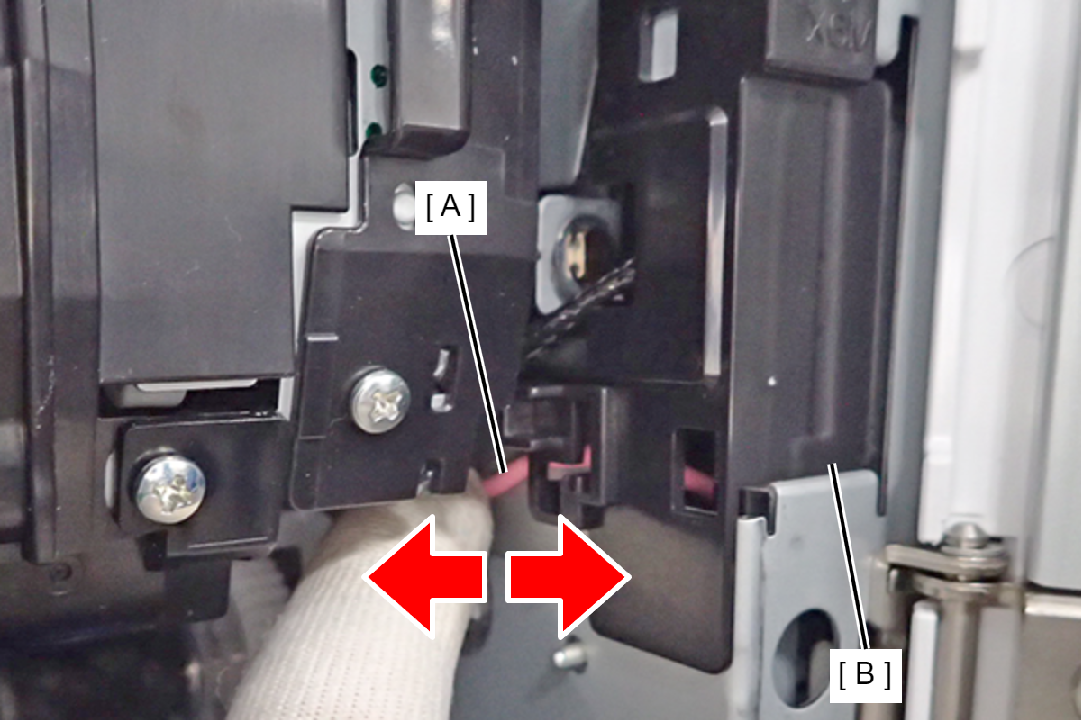
- Pass the high-voltage cable (B) through the cutout of Connector Cover Belt Rear (A) as shown below, and then insert the lower hook of the cover.
- Remove the screw and remove the High Voltage Cable Cover (A).
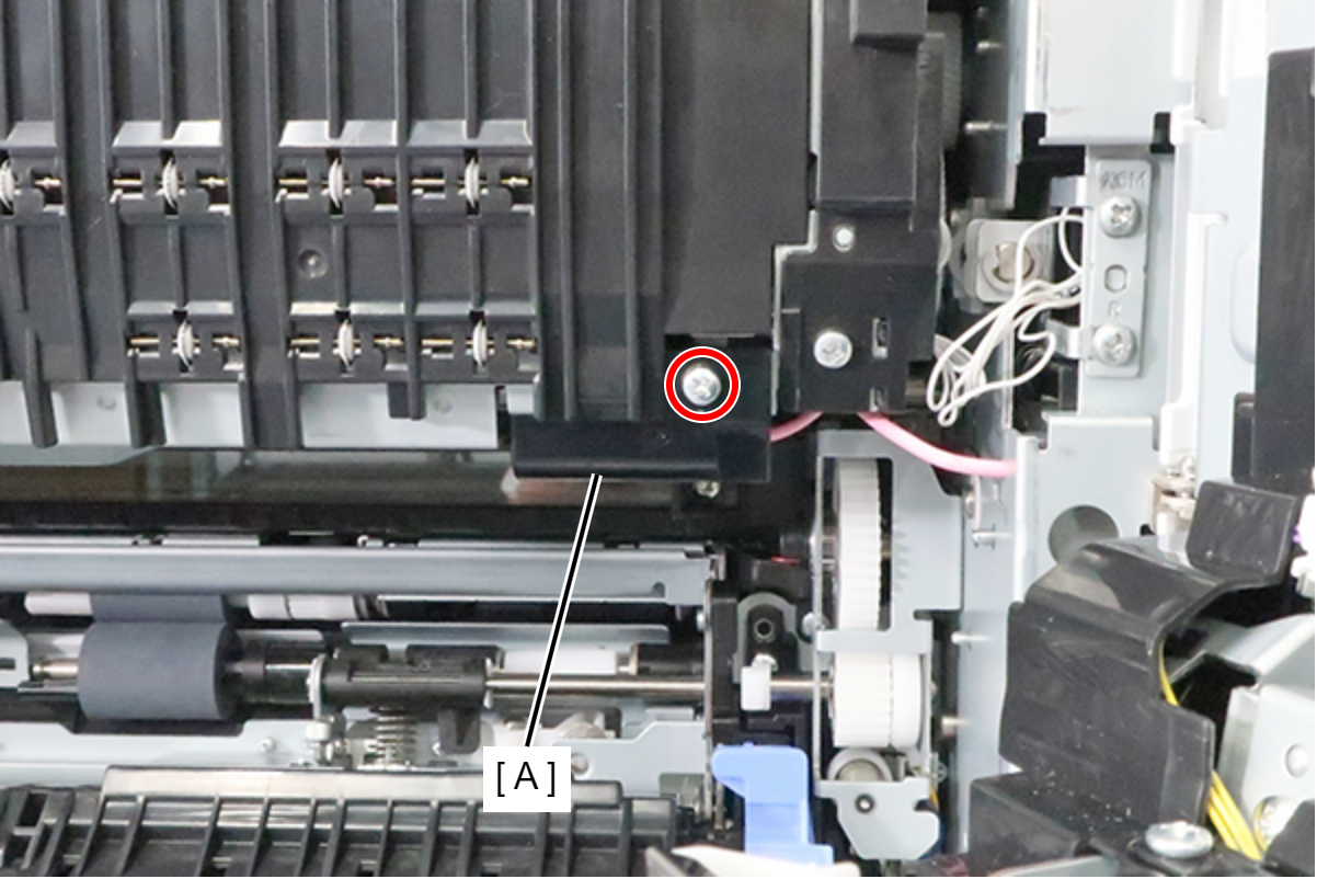
- : 3x8D
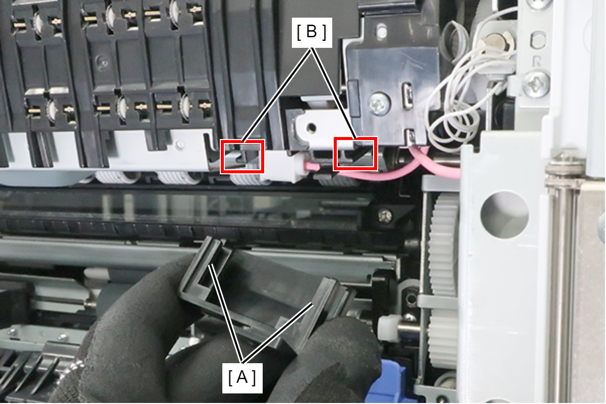
Assembly / 組み立てAlign the High Voltage Cable Cover (A) with the rail portion (B) and install.
- Disconnect the cable from the connector (A), remove the 2 screws, and remove the Belt Attached Component Rear.
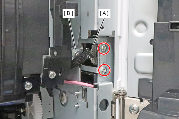
 : 3x6M
Assembly / 組み立てFit the body frames plates (B) into the two grooves of the Belt Attached Component Rear (A).
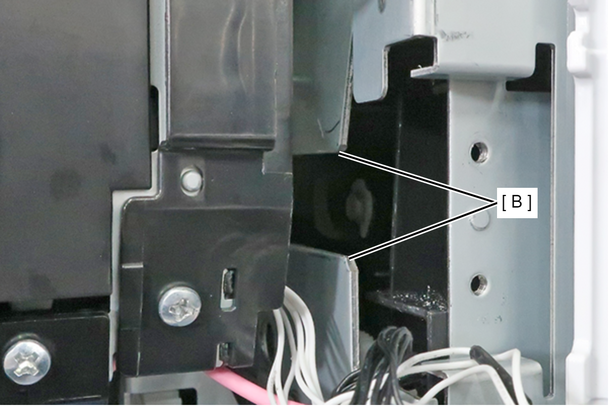
OK
NG
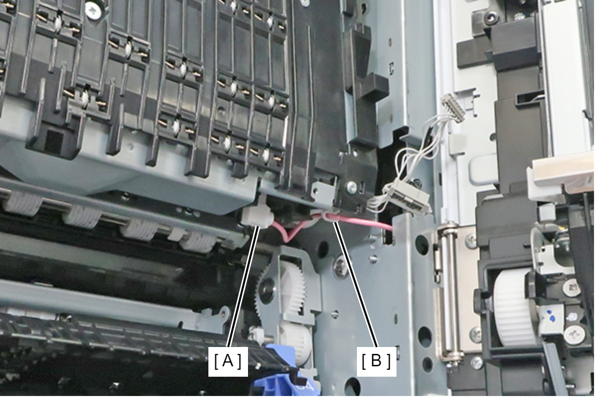
- Remove the high voltage cable (A), and release it from the clamp (B).
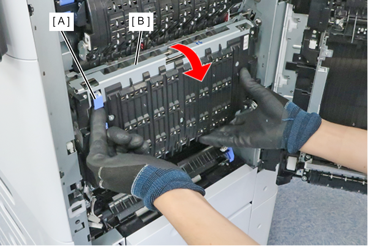
- Pull the lever (A) to open the belt unit (B).
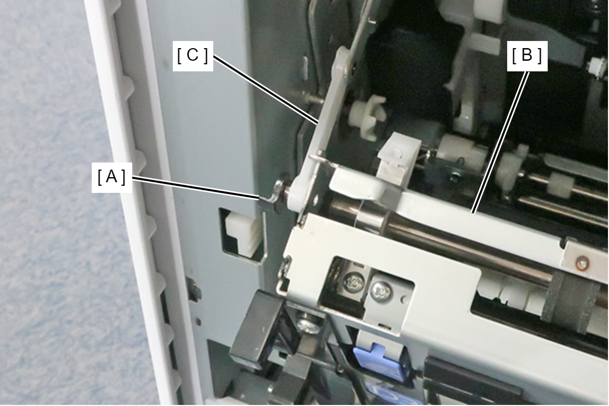
- Remove the C-ring (A), and remove the Belt Arm (C) from the shaft of the Belt Unit (B).
 Caution / 注意
When the belt arm (C) is removed, the Belt unit (B) will drop.
Remove the belt arm (C) while holding the Belt unit (B).
- While holding the Belt Unit (A) with both hands, pull it out horizontally toward the front and remove the Belt Unit.
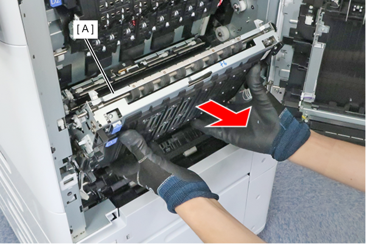 Caution / 注意
Do not touch the belt surface (A) of the belt unit.
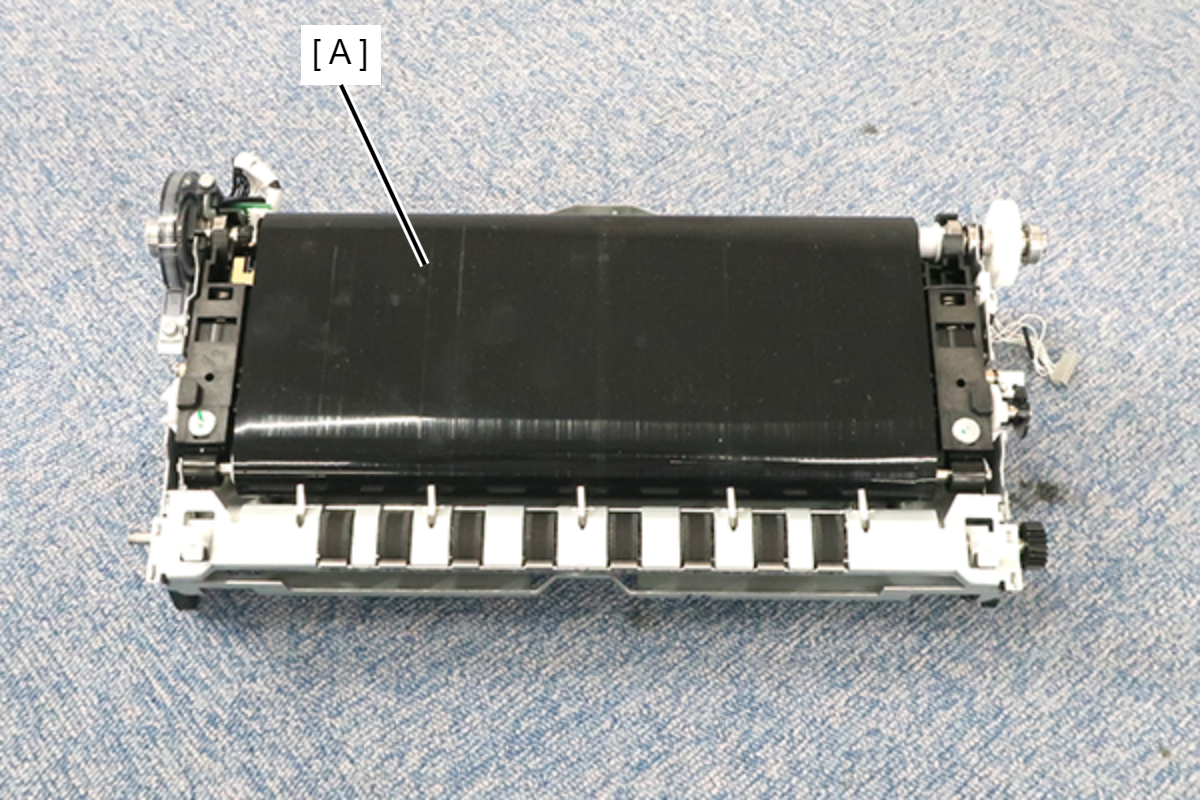 Assembly / 組み立て
- When installing the Belt Unit (A), insert it from the rear surface side bearing (B).
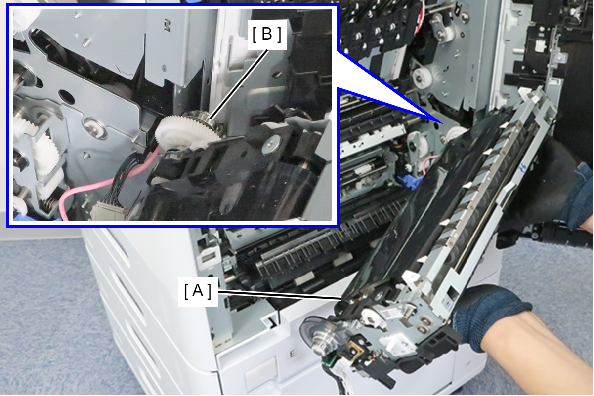
- After installing the Belt Unit (A), confirm that the front side bearing (B) is properly set on the rail (C) of the main unit.
- When installing the Belt Unit (A), insert it from the rear surface side bearing (B).
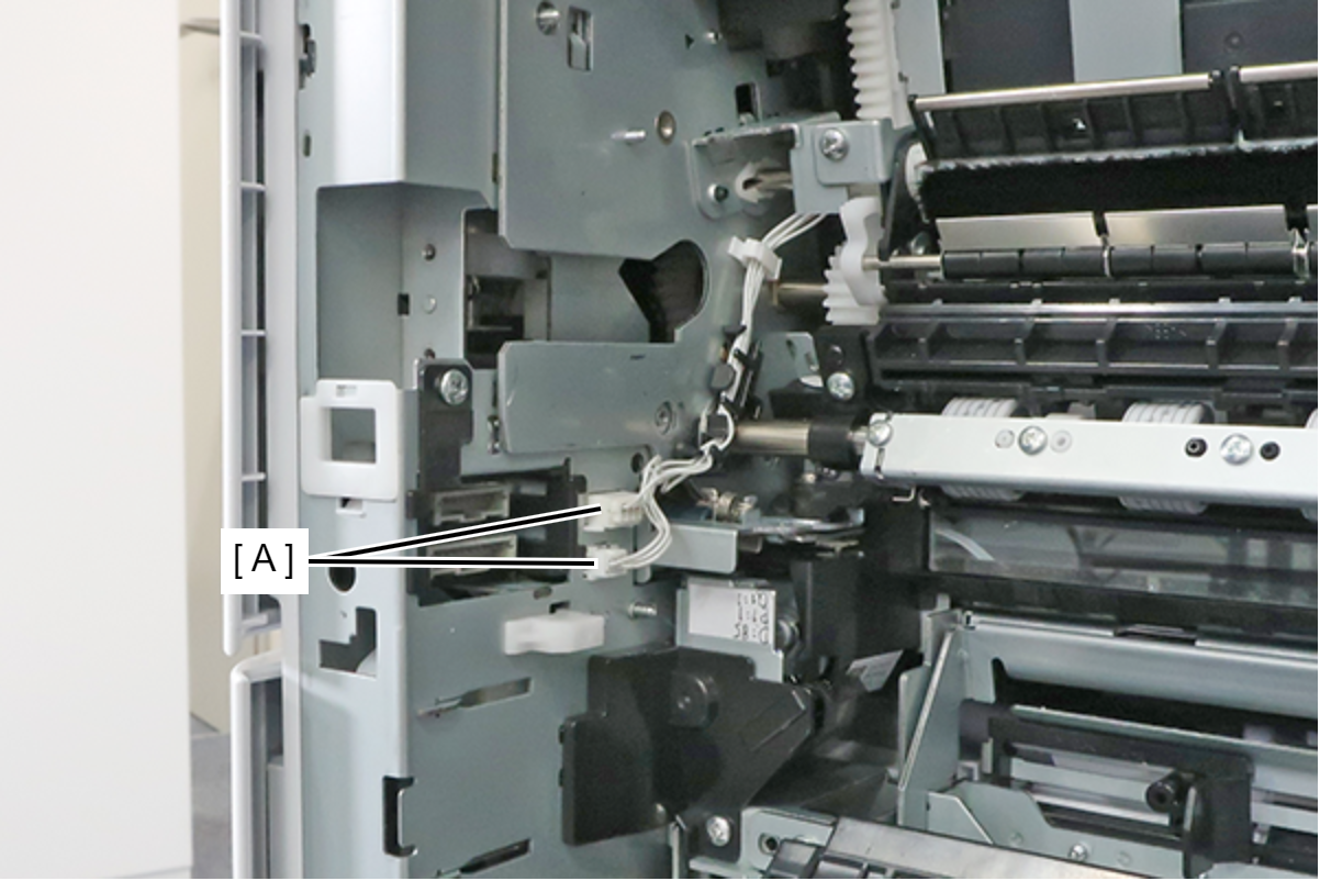
- Disconnect the cables from the 2 connectors (A).
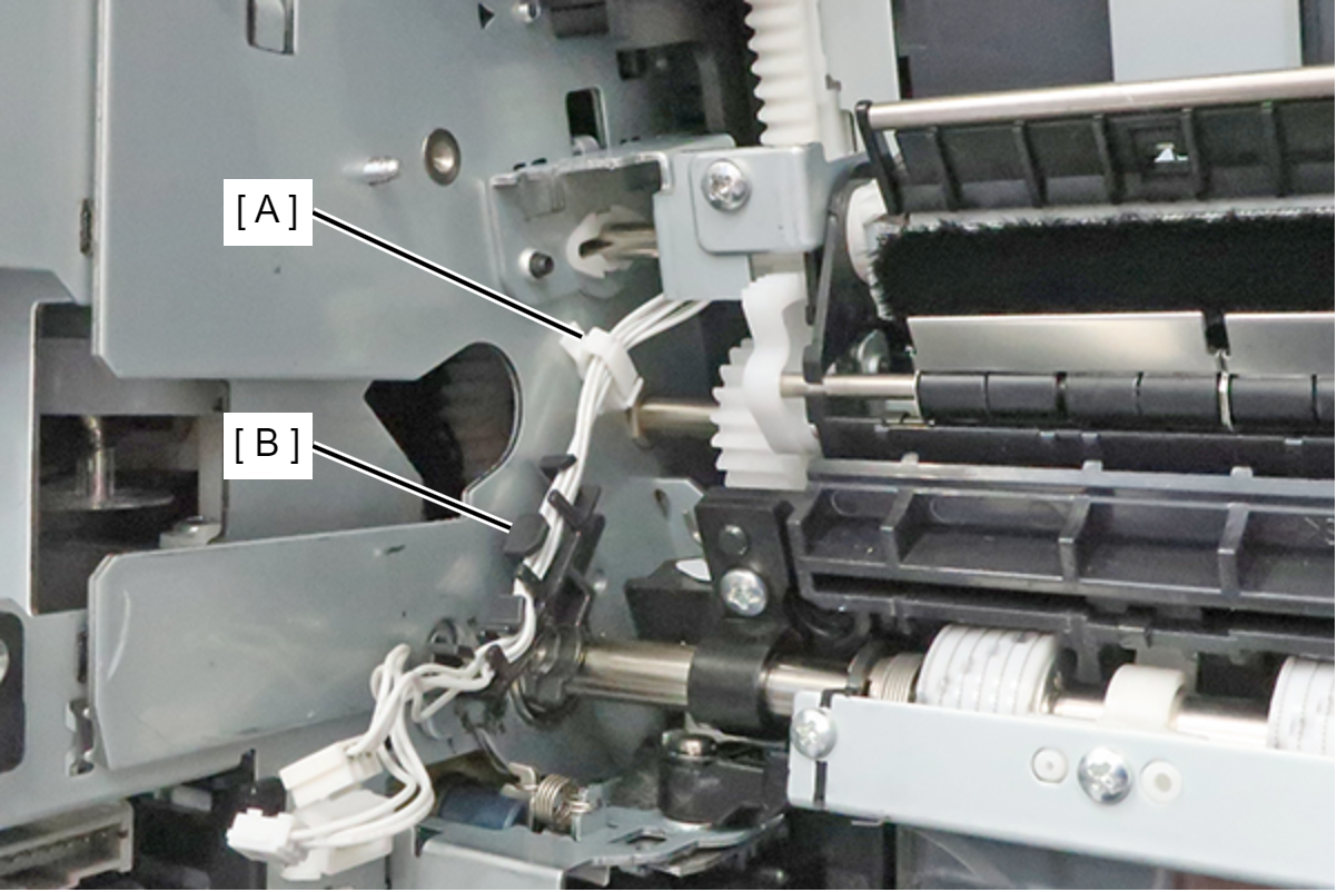
- Release the cable from the clamp (A) and cable guide (B).
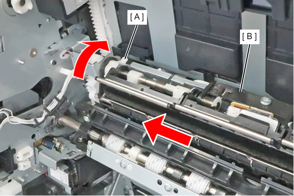
- Remove 1 screw and slide the Anti Static Brush Unit (A) in the direction of the arrow to remove it.
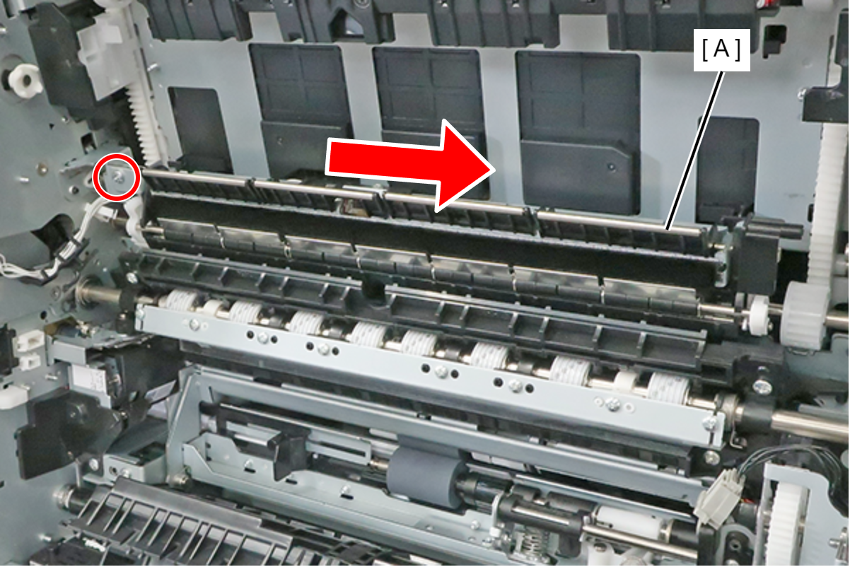
- : 3x8M
Assembly / 組み立てPush up the cam (A) toward the back and slide the Anti Static Brush Unit (B) toward the front to attach it.
| Check Point / チェックポイント |
After replacing this part, you need to run the menu from the service support mode. (If you ran the Before-replacement menu before replacing the part, it will start automatically when you turn the power on.) |