
Head Unit
 Check Point / チェックポイント Check Point / チェックポイント |
When replacing this part, you need to run the menu from the service support mode before replacing it. |
- Remove the screw and remove the Left Cover Upper (A) in the direction of the arrow.
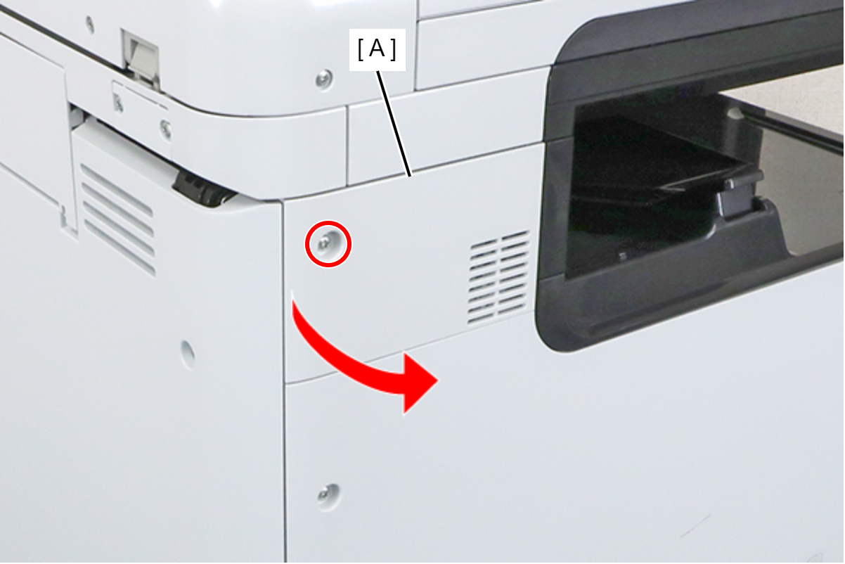
 : 3x8D
- Remove the 4 screws and remove the SCN Fixing Plate (A).
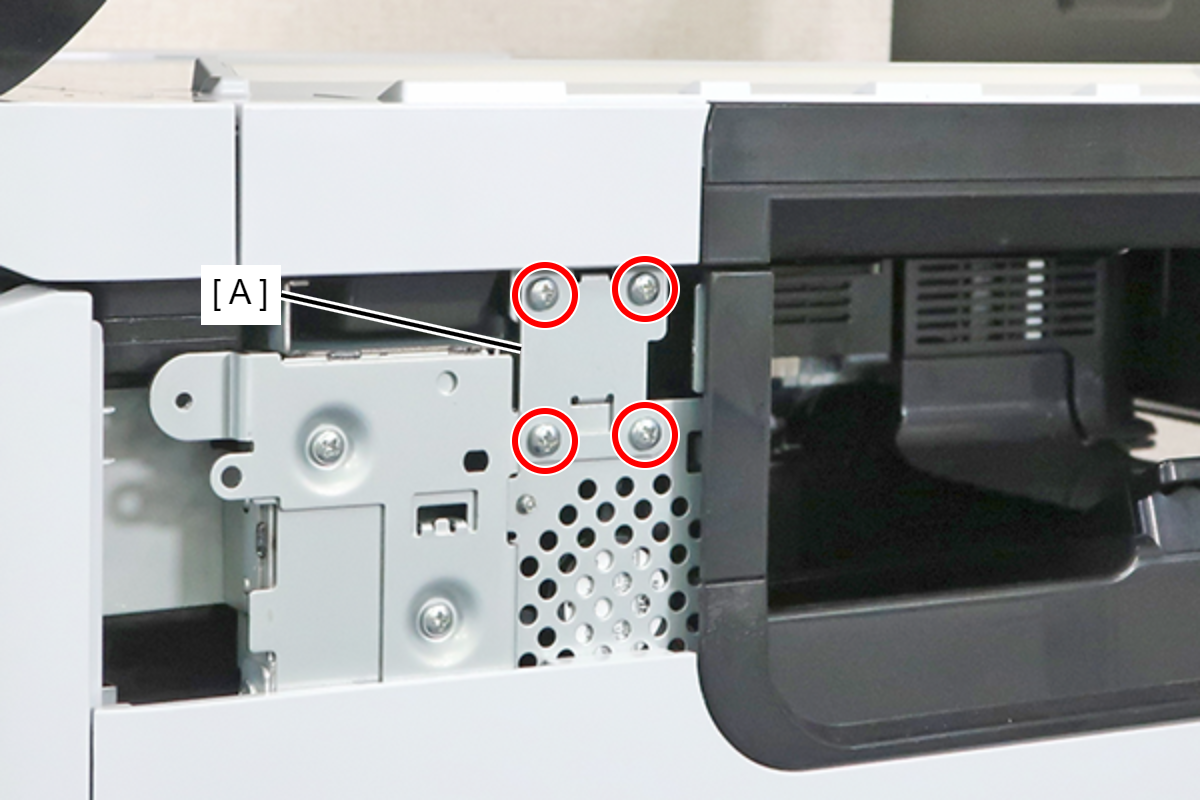
- : 3x8M
 Caution / 注意
Be sure to completely remove the SCN Fixing Plate.
If you attempt to carry out the operation without completely removing the screws and leaving the lower 2 screws removed, there is a risk of an accident, such as pinching your finger, when opening or closing the SCN.
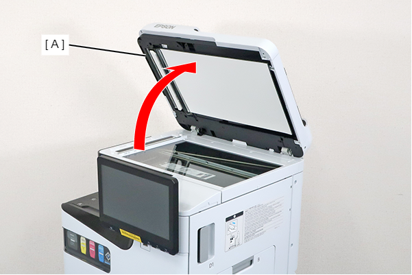
- Open the ADF (A).
- Remove the screw and slide the Panel Upper Cover (A) in the direction of the arrow to remove it.
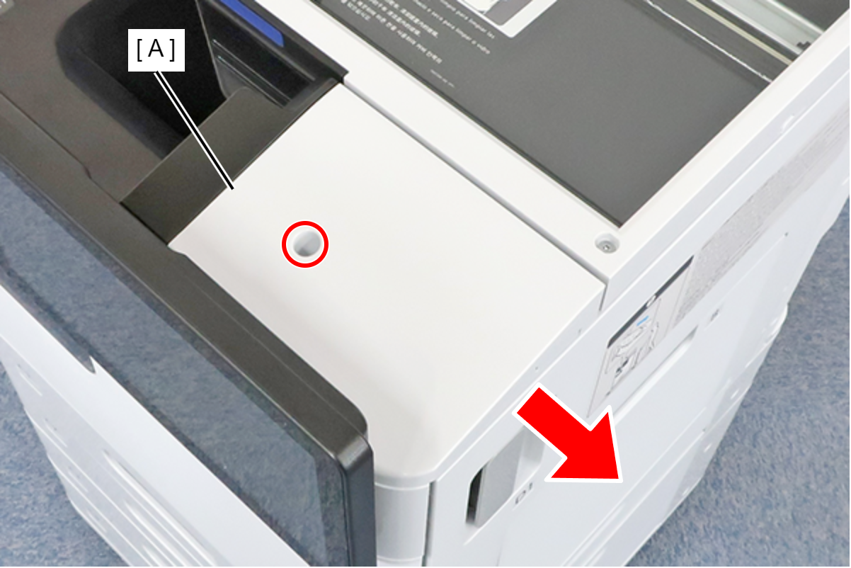
- : 3x8D
- Remove the 2 screws and the spacer.
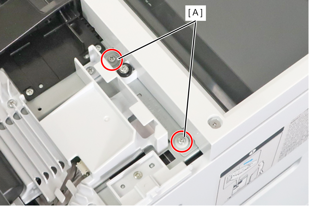
- : 3x8D
- Remove the screw and remove the spacer (A).
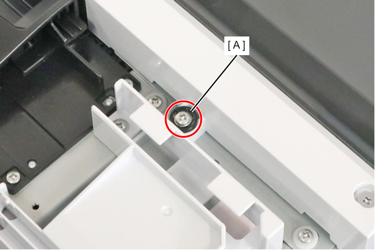
 : 3x18MW
- Remove the screw, and attach the spacer (A) removed in the preceding step.
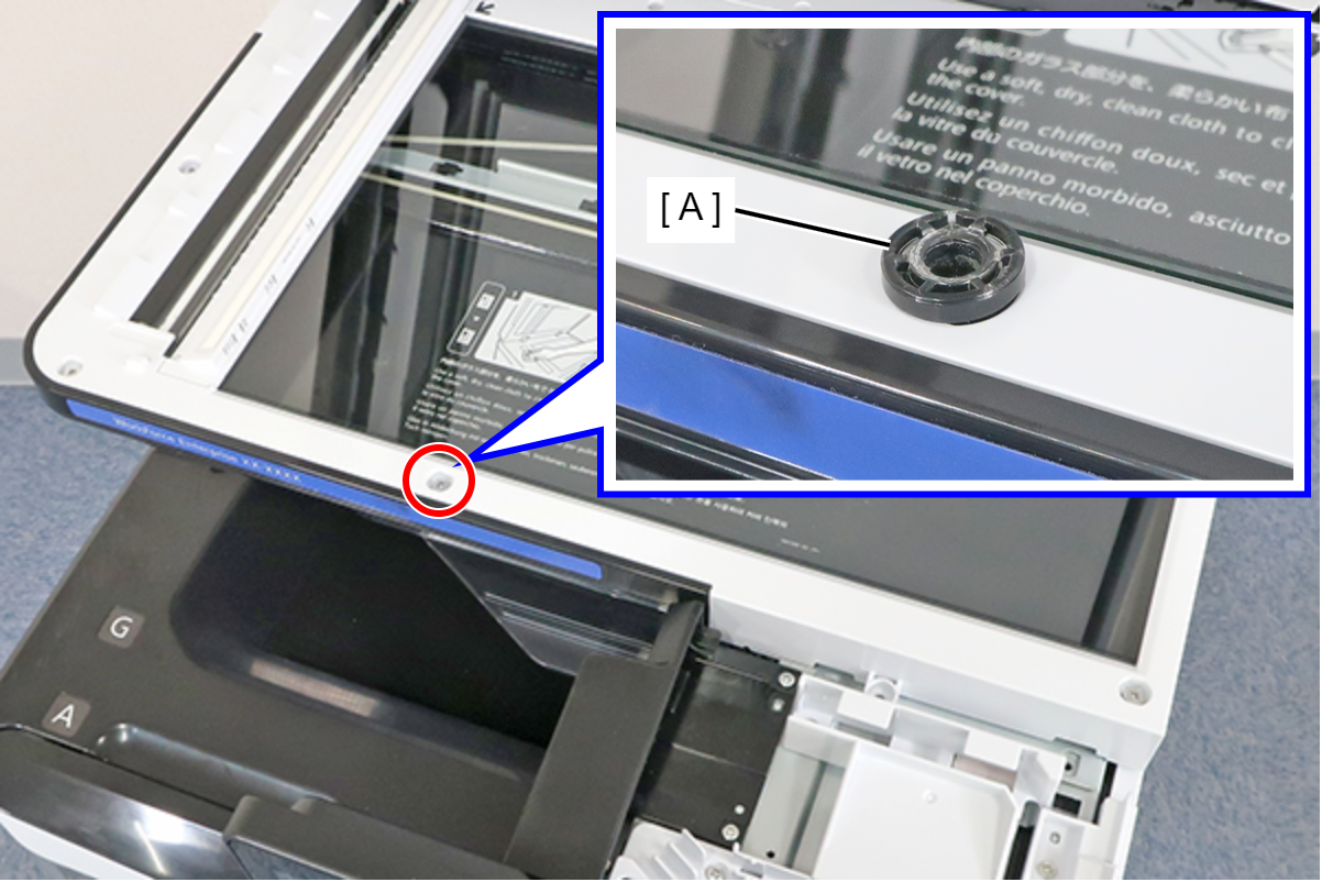
- : 3x5D
- Close the ADF (A), and fix the ADF and SCN Unit (B) with the screw that had been fixing the spacer in place.
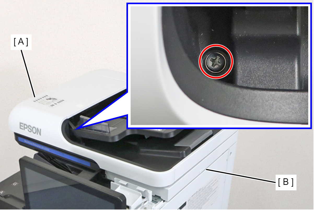
- : 3x18MW
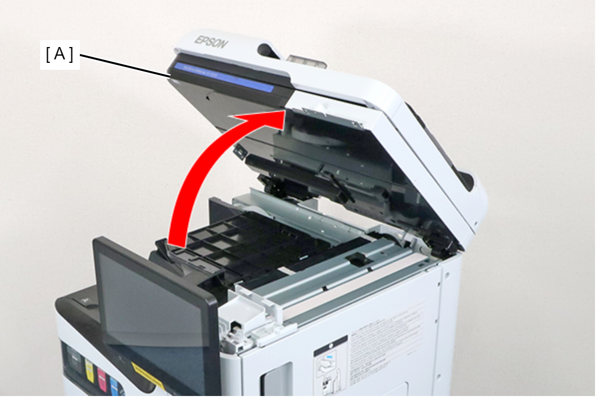
- Raise the ADF/SCN Unit (A).
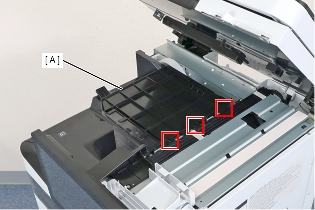
- Lift the duplex tray Assy (A), remove the 3 hooks, and remove the duplex tray Assy (A).
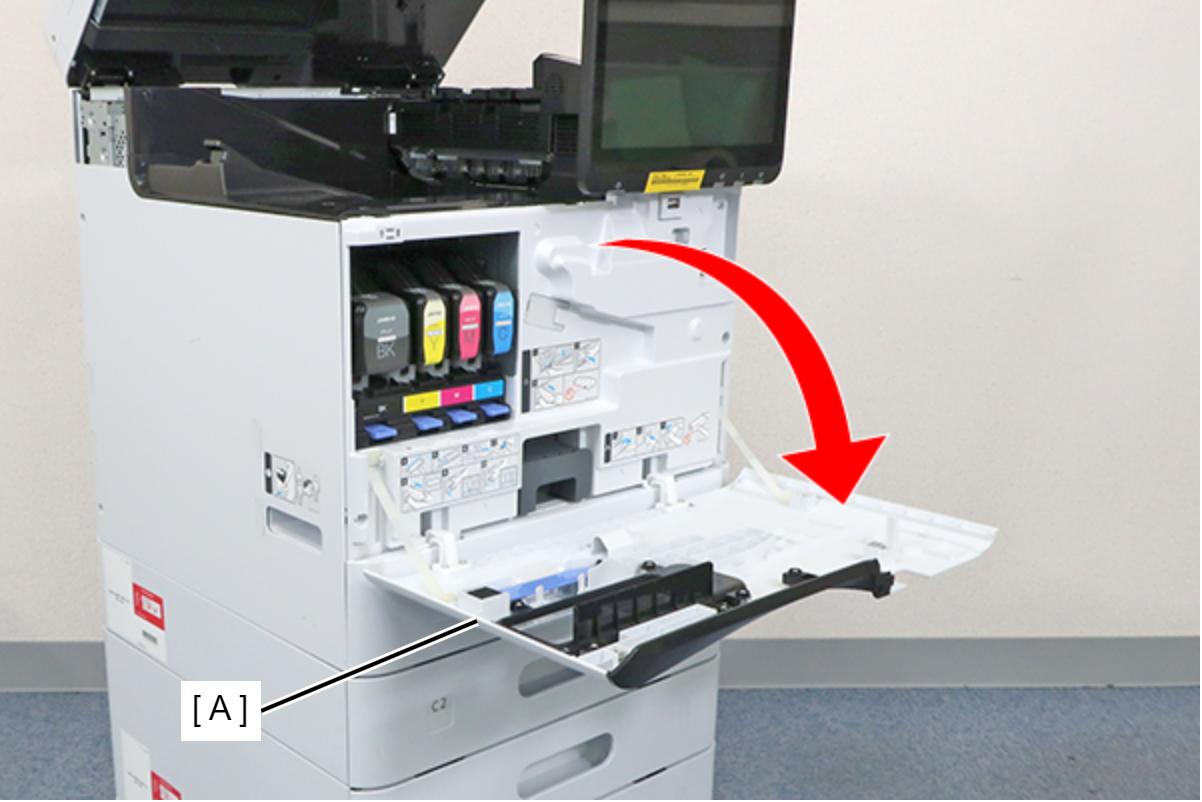
- Open the Front cover (A).
- Remove 4 screws and remove the FD Stacker Assy (A).
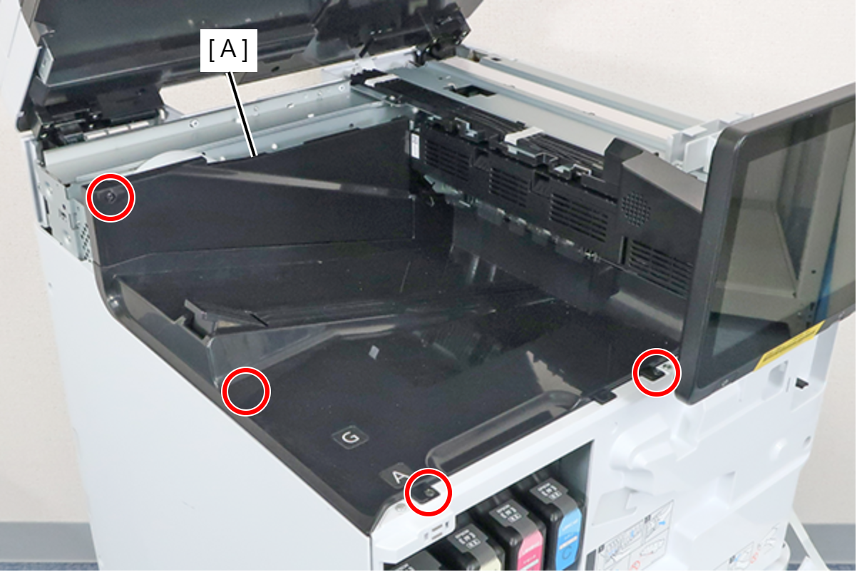
- : 3x8D/BK
- Remove the 2 screws and remove the Head Joint (A).
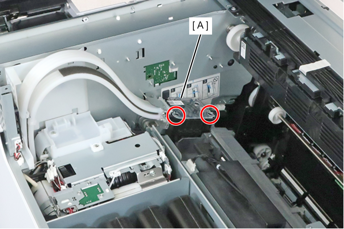
- : 3x20M
Check Point / チェックポイントThe screws are provided with a stopper, so they cannot be completely removed.
- Attach the protective cap (B) to the connector of the Head Joint (A).
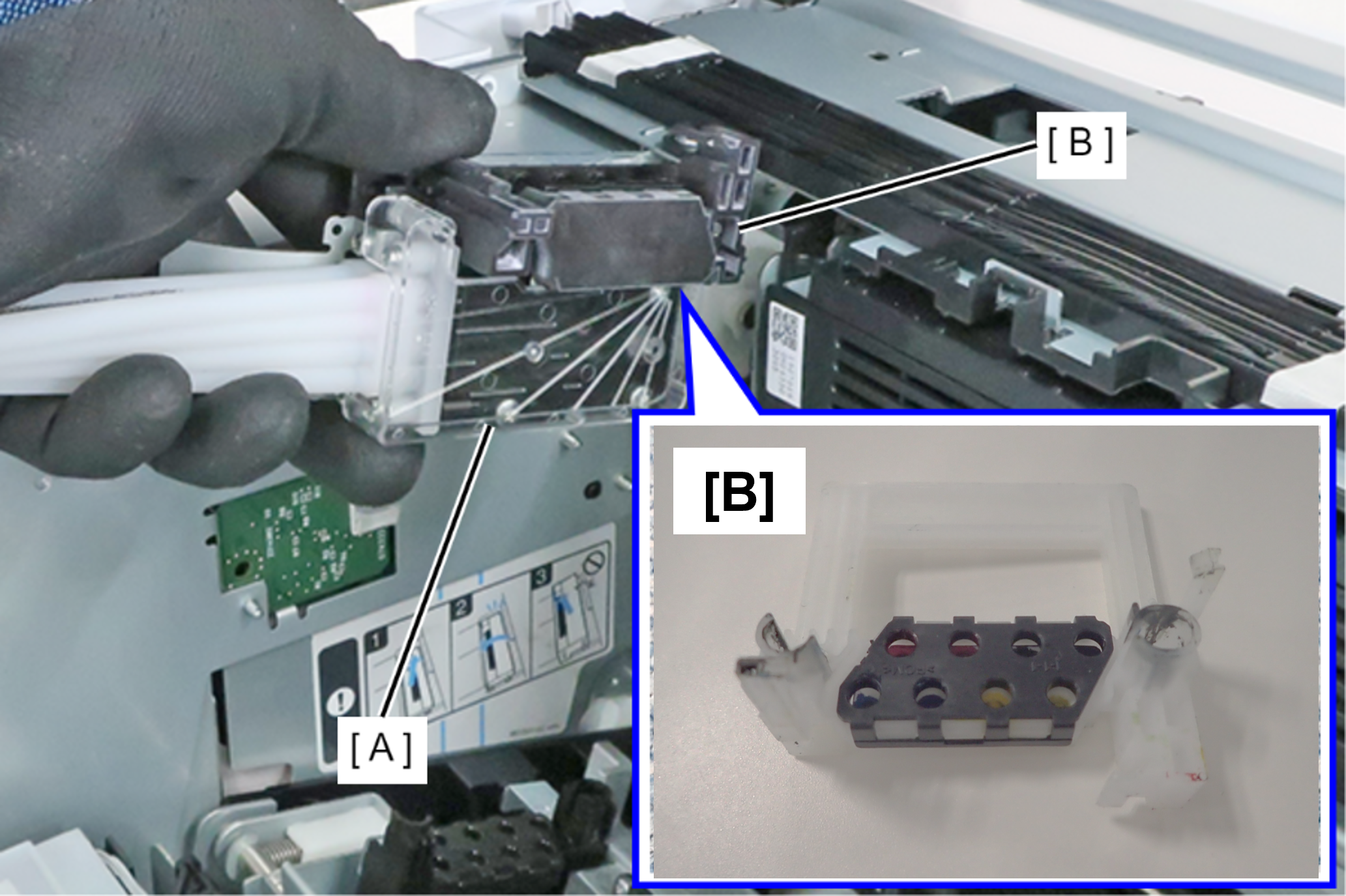 Caution / 注意
There is a risk that ink will drip, so do not shake the Head Joint strongly before attaching the protective cap.
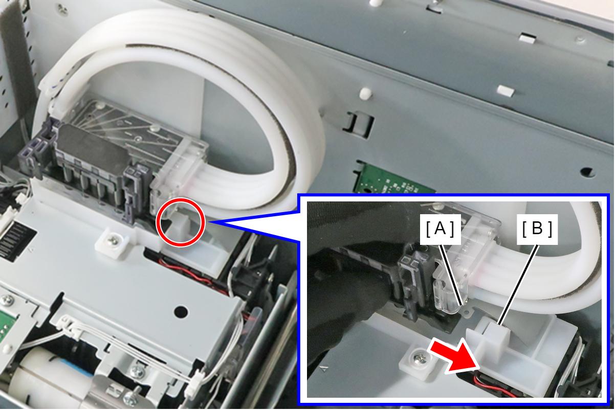
- Fix the Head Joint by engaging the frame protrusion (A) of the Head Joint with the Ink System Unit hook (B).
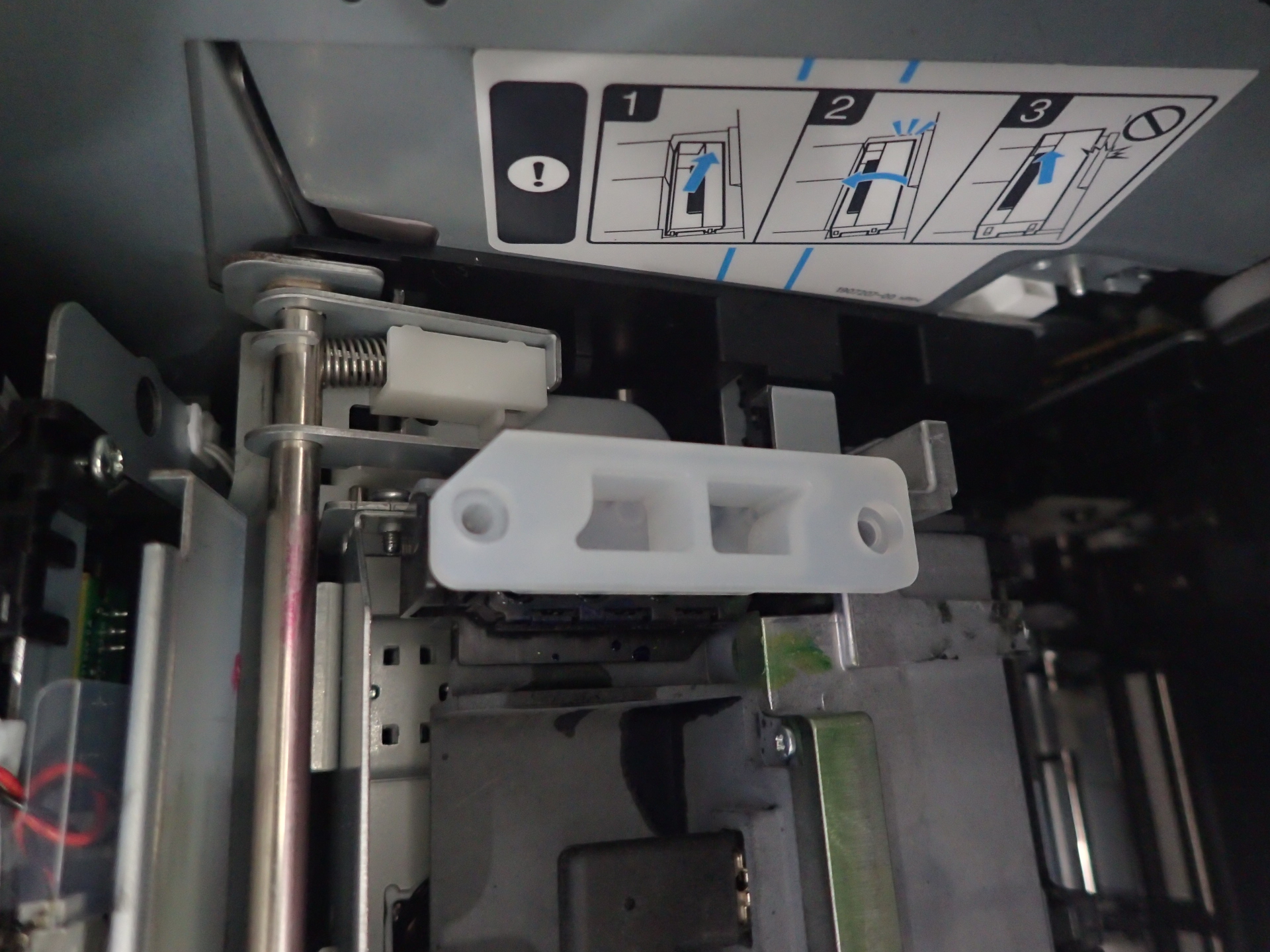
- Attach the protective cap (B) to the connector of the Head Unit (A).
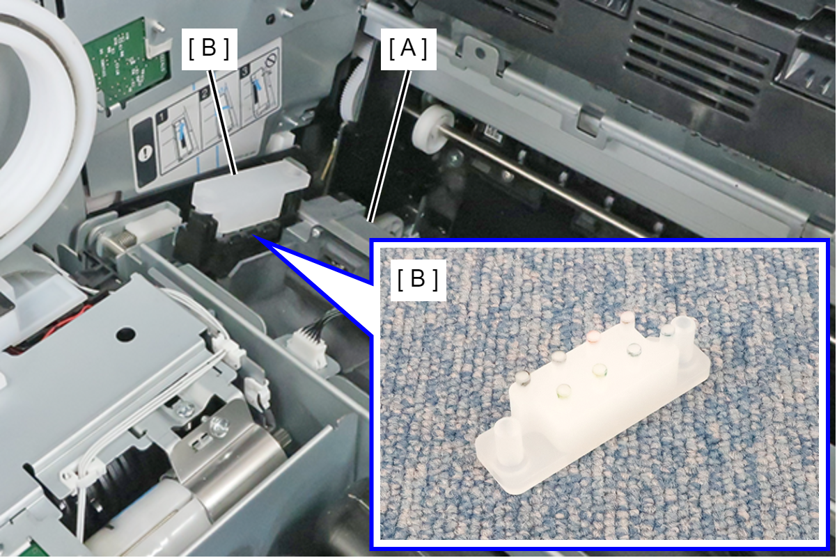
 Note / 補足
- Attach the protective cap so that the notch faces the left side of the main unit. It is configured such that it cannot be attached facing the right side of the main unit.
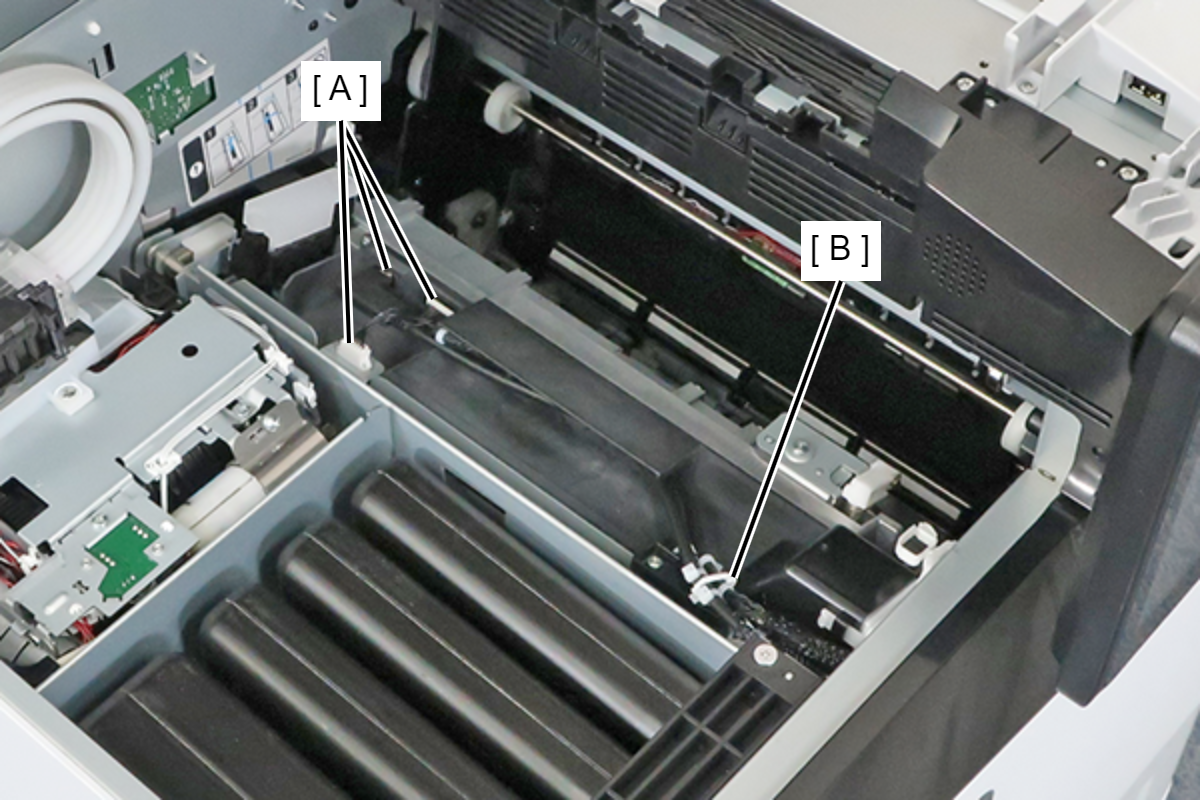
- Remove the cables from the 3 connectors (A) of the Head Unit, and release the cables from the clamp (B).
 Assembly / 組み立て
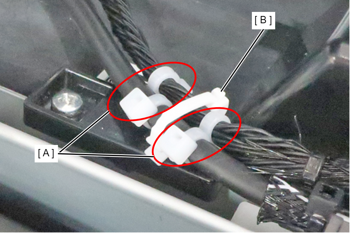
Fix the cable ties (A) attached to the cable with the clamp (B) in the area between the cable ties.
- Remove the 2 screws and remove the Duct (A).
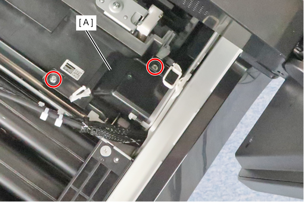
- : 3x6M
Check Point / チェックポイントThe screws are provided with a stopper, so they cannot be completely removed.
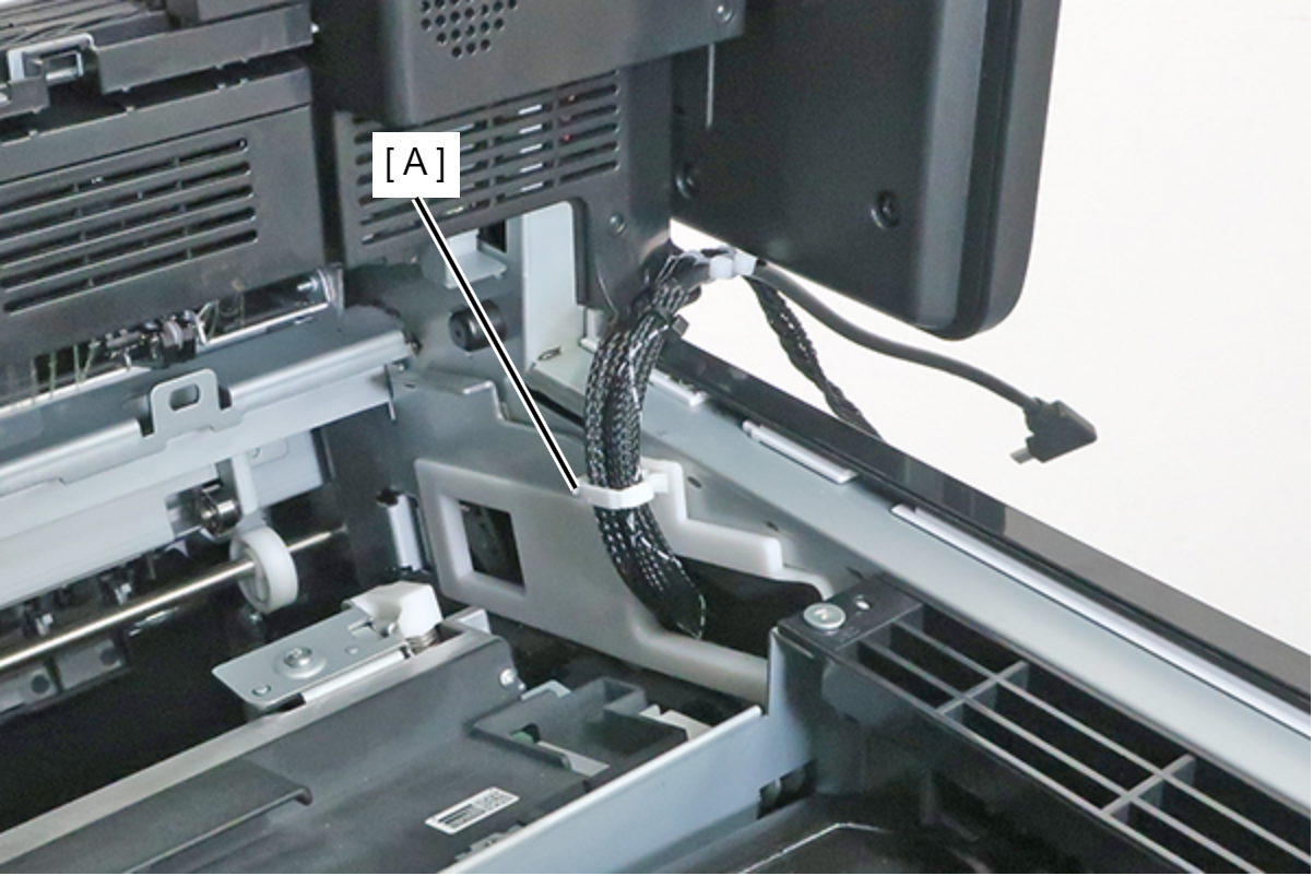
- Fix the cables with the clamp (A), then withdraw them.
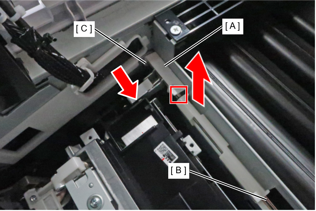
- Raise the cam (A) to remove the hook from the Head Lock Shaft (B), then slide the cam toward the inward side of the product and remove it from the hole (C).
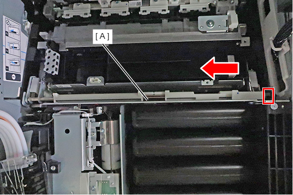
- Slide the Head Lock Shaft (A) and remove it from the hole in the rear side frame, then remove the Head Lock Shaft.
 Assembly / 組み立て
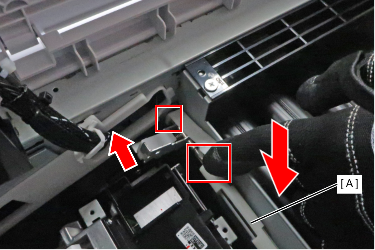
- Insert the Head Lock Shaft (A) into the frame hole in the order from the front side to the rear side.
- Insert the cam (B) into the hole in the front side of the frame, align the hook with the groove in the Head Lock Shaft and fix it in place.
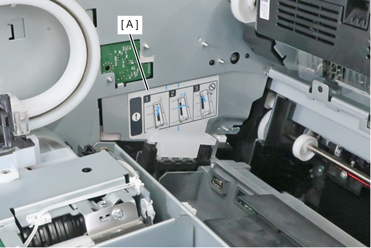
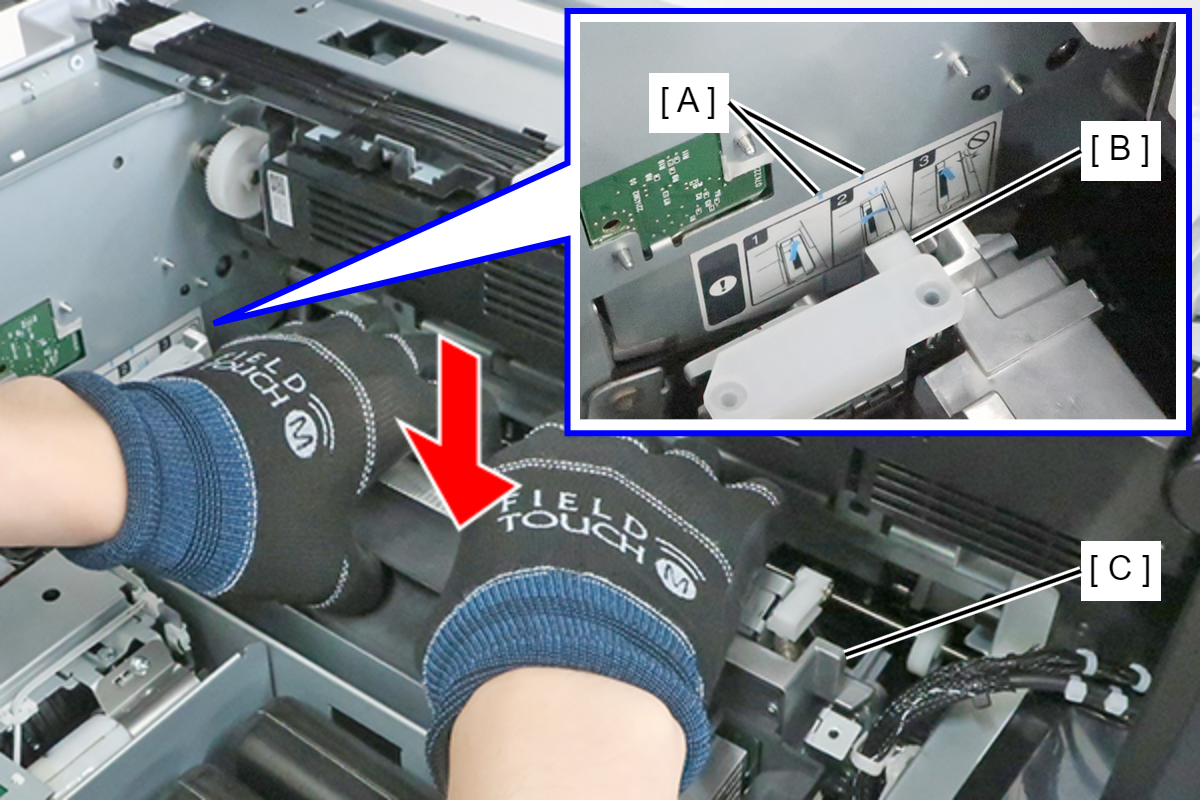
- Refer to the label (A) while carrying out the task.
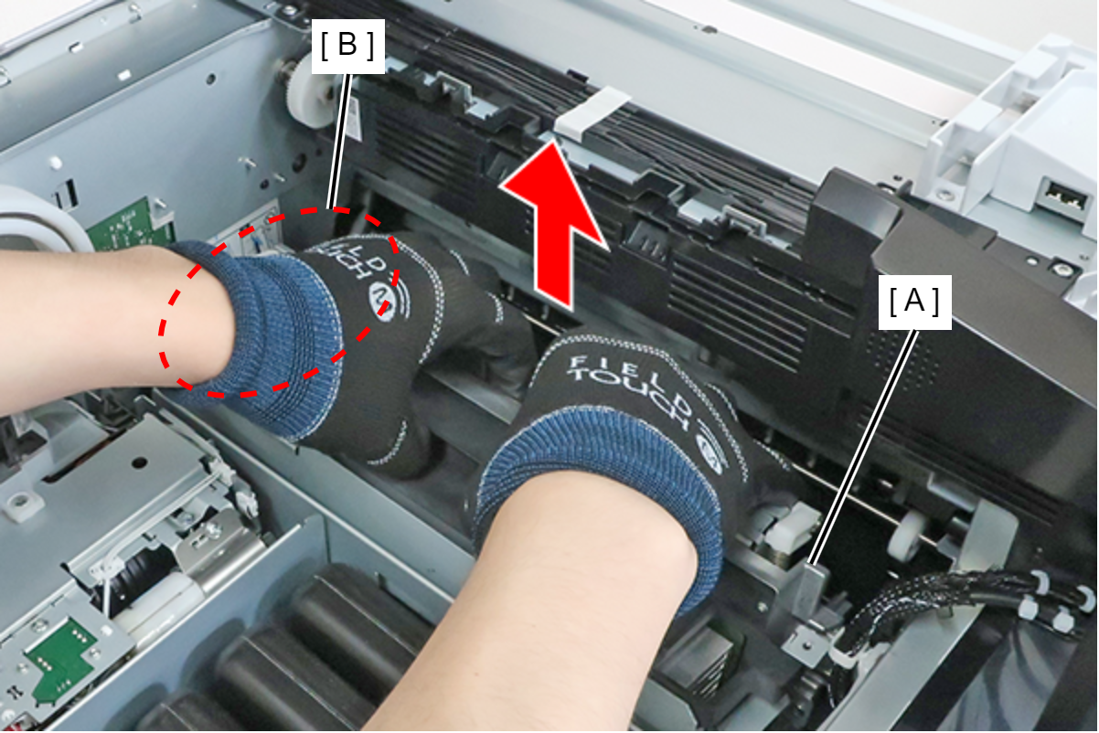
- Hold the Head Unit (A) and raise it straight up until the position where the rear side (B) interferes.
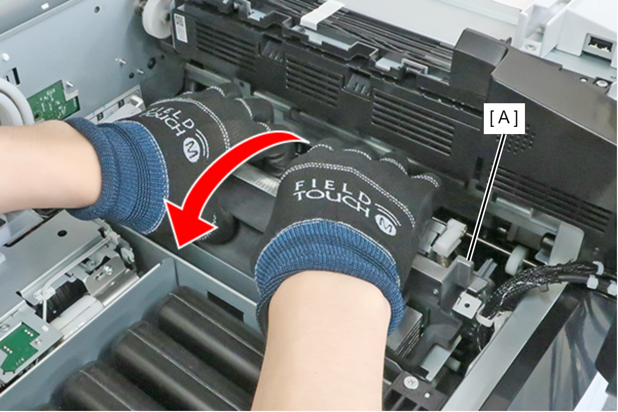
When the position where the rear side (B) interferes is reached, rotate the Head Unit (A) in the direction of the arrow to avoid the interfering portion, and remove the Head Unit (A).
The nozzle surface (A) can easily come into contact with the plate of the EJ Unit, so exercise caution.
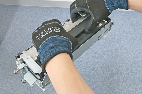
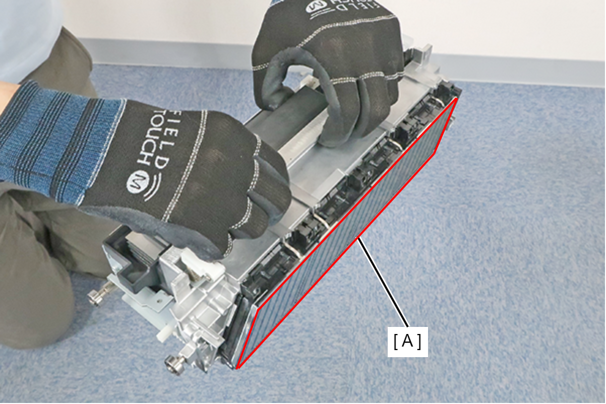 Caution / 注意
Hold the Head Unit with both hands as shown below.
 Assembly / 組み立て
Align the protrusion (B) of the Head Unit with the reference line (A) of the label, and lower the Head Unit (C) straight down to install it.
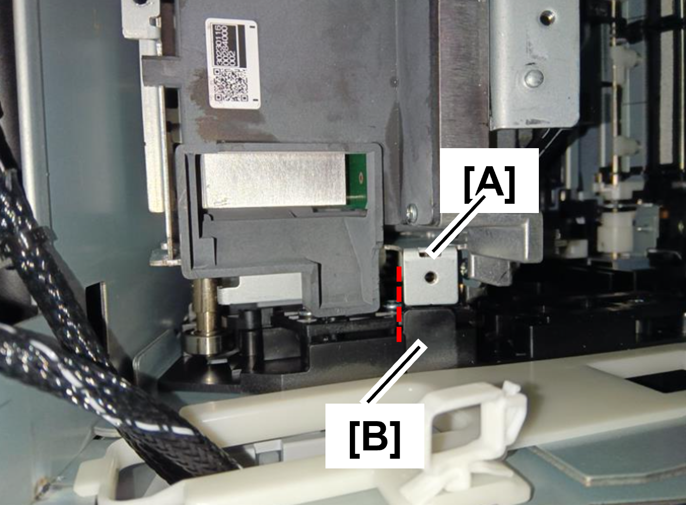
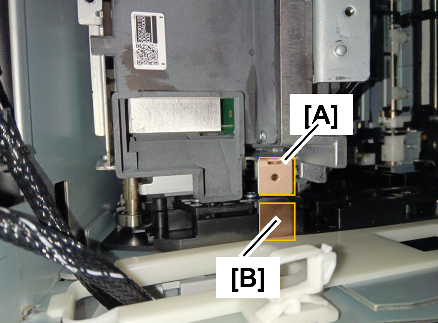
Check the head unit is in the correct position, both on the front and rear sides.
- Front side
The height and position of the protrusion on the head unit and the protrusion on the main unit are the same.
Position
Hight
- Rear side
The height and position of the protrusion on the head unit and the protrusion on the main unit are the same.
Position
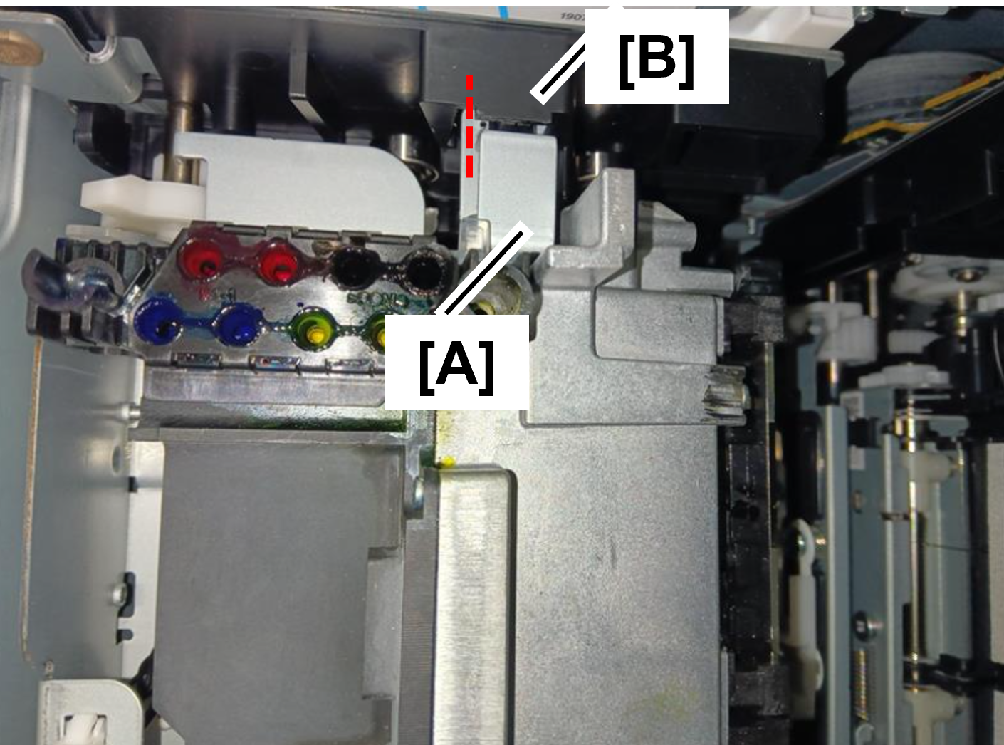
Hight
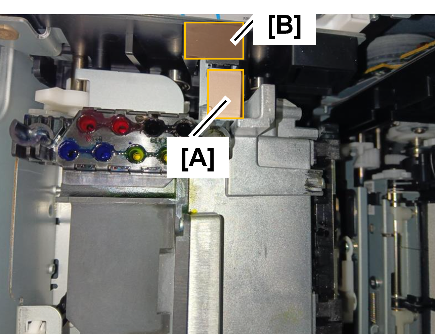
- Hold the Head Unit (A) and raise it straight up until the position where the rear side (B) interferes.
- Packing the removed head unit. Head ASP Unpacking, Repacking, and Handling Jigs
| Check Point / チェックポイント |
After replacing this part, you need to run the menu from the service support mode. (If you ran the Before-replacement menu before replacing the part, it will start automatically when you turn the power on.) |