
Protocol log
 Note / 補足 Note / 補足 |
|
Printing Procedure
Manual |
[Fax] > [Menu] > [Fax Report Output] > [Protocol log] |
|---|
Setting Method
Automatic print settings |
Fax parameter setting mode #006 allows you to set automatic printing for each communication. |
|---|---|
Save only in case of error/Print setting |
Fax parameter Setting mode #005 can be set to save/print only error communications. |
Save settings. |
Can set the protocol log to be saved/printed in Fax parameter Setting mode #007. |
Output Sample
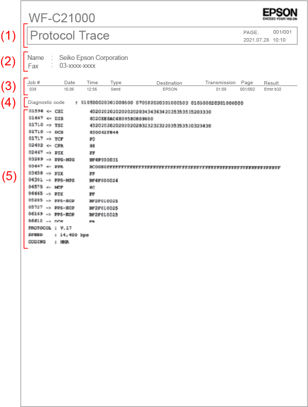
| (1) | Subject | Report name *Report name is protocolMonitorwritten as log |
|---|---|---|
| PAGE. | Number of pages to be reported (number of pages/total number of pages) | |
| Date and time | Printed time (yyyy.mm.dd hh:mm) |
|
| (2) | Name | Registered sender name |
| Fax | Registered sender name | |
| (3) | Reception number | Job number |
| Date Time | Starting time of communication | |
| Type | Sending/Receiving/Polling Sending/Polling Reception/PC Sending/Forwarding |
|
| Destination number | 「Indications of destination number (in priority order)」 | |
| Communication time | mm:ss | |
| Number of pages | Memory sending: Number of pages of communication succeeded/total number of pages |
|
| Communication result | Succeeded: OK |
|
| (4) | DIS(DTC) / DCS | 「How to read DIS(DTC)/DCS」 |
| (5) | Command / Response log | 「How to read the Command / Response log」 |
How to read DIS(DTC)/DCS
Before starting communication, the sender and the receiver communicate their functions to each other before starting communication, and determine the communication function and speed.
The receiving fax machine transmits its own functions to the sending fax machine using a DIS (DTC) signal. The sending fax machine receives the DIS signal from the receiving fax machine, selects the maximum function set by the sending side, which is a function that can be used by both the sending and receiving sides, and receives the selected communication mode using the DCS signal. Send it to the side fax.
By checking the DIS (DTC) information, you can find out the contents of the capability declaration of the receiving fax machine, and by checking the DCS information, you can find out the communication mode selected by the sending fax machine.
Only one protocol log is recorded and printed for each communication. If the protocol log becomes too long to fit on one page due to multi-page communication, the first protocol log will be deleted and only the last protocol log will be recorded and printed.
DIS(DTC)/DCS records and prints on top of the protocol log so that the contents can be seen even if the first protocol log is deleted.
Fax communications are made in accordance with ITU recommendations, and the main relevant recommendations are "T.30" and "T.4".
Documents of these recommendations are published online and can be downloaded from the following sites.
- T.30 Document facsimile transmission procedure on the general switched telephone network
https://www.ttc.or.jp/application/files/3115/5434/5126/JT-T30v18.pdf - T.4 Document transmission group 3 Terminal characteristics of facsimile machine
https://www.ttc.or.jp/application/files/8215/5434/4915/JT-T4v13.pdf
DIS(DTC)/DCS reads the contents of FIF (Facsimile Information Field) by referring to the bit assignment table of DIS(DTC)/DCS. The DIS(DTC)/DCS bit allocation table is described in "T.30 Document facsimile transmission procedures over general switched telephone networks".
- 5.3.6.2 Facsimile Information Field (FIF) Table 5-1 JT-T30 (ITU-T T.30)
DIS (DTC) Capability Bit Table
To refer to the bit assignment table and data, rearrange the upper and lower bits every 2 bytes of data.
DIS example: 8020C28AC480D5838018
- FCS=80
- FIF=20 C2 8A C4 80 D5 83 80 18
hex |
2 |
0 |
C |
2 |
8 |
A |
||||||||||||||||||
|---|---|---|---|---|---|---|---|---|---|---|---|---|---|---|---|---|---|---|---|---|---|---|---|---|
bin |
0 |
0 |
1 |
0 |
0 |
0 |
0 |
0 |
1 |
1 |
0 |
0 |
0 |
0 |
1 |
0 |
1 |
0 |
0 |
0 |
1 |
0 |
1 |
0 |
bit no. |
8 |
7 |
6 |
5 |
4 |
3 |
2 |
1 |
16 |
15 |
14 |
13 |
12 |
11 |
10 |
9 |
24 |
23 |
22 |
21 |
20 |
19 |
18 |
17 |
| bit no. | DIS/DTC | data | Description | |
|---|---|---|---|---|
| 1 | 1 | Store-and-forward Internet facsimile simple mode (TTC standard JT-T37) | 0 | |
| 2 | Pending | 0 | ||
| 3 | Real-time Internet facsimile (TTC standard JT-T38) | 0 | ||
| 4 | 3rd generation wireless mobile telecommunication network | 0 | ||
| 5 | Pending | 0 | ||
| 6 | ITU-T Recommendation V.8 Capability | 1 | Function enable | |
| 7 | Frame size 0=256 Octet priority 1=64 | 0 | ECM frame size =256 | |
| 8 | Pending | 0 | ||
| 2 | 9 | Ready to transfer (polling) facsimile documents | 0 | No polling fax is ready |
| 10 | Operation#1 of received fax | 1 | Function enable | |
| 11 | Data signal speed 00000=V.27terFB 0010=Not used 0001=Not used 0011=Not used 0100=V.27ter 0110= Pending 0101= Pending 0111= Pending 1000=V.29 1010= Not used 1001= Not used 1011= Not used 1100=V.27ter,V.29 1110= Disable 1101=V.27ter,V.29,V17 1111=Pending |
0 | V.27terFB Notice) When V8 mode (S-G3) starts, this bit becomes invalid (0000). |
|
| 12 | 0 | |||
| 13 | 0 | |||
| 14 | 0 | |||
| 15 | Linear density (fine / FINE) R8 x 7.7 l / mm or 200 x 200 dpi | 1 | Function enable | |
| 16 | Coding method: MMR | 1 | Function enable | |
| 3 | 17 | Recording width ability 00=A4 10=A4/B4 01=A4/B4/A3 11=Disable |
1 | A4/B4/A3 |
| 18 | 1 | |||
| 19 | Recording width ability 00=A4(297mm) 10=A4(297mm) and B4(364mm) 01= unlimited 11= disable |
0 | Unlimited | |
| 20 | 1 | |||
| 21 | Minimum scan time capability of the receiver (Linear density = Std / Fine) 000=20/20ms 100=5/5ms 101=40/20ms 001=40/40ms 011=10/5ms 111=0/0ms 010=10/10ms 110=20/10ms |
0 | 20/20ms | |
| 22 | 0 | |||
| 23 | 0 | |||
| 24 | Extend field | 1 | With extension | |
DIS example: 8020C28AC480D5838018
- FCS=80
- FIF=20 C2 8A C4 80 D5 83 80 18
| hex | C | 4 | 8 | 0 | D | 5 | ||||||||||||||||||
|---|---|---|---|---|---|---|---|---|---|---|---|---|---|---|---|---|---|---|---|---|---|---|---|---|
| bin | 1 | 1 | 0 | 0 | 0 | 1 | 0 | 0 | 1 | 0 | 0 | 0 | 0 | 0 | 0 | 0 | 1 | 1 | 0 | 1 | 0 | 1 | 0 | 1 |
| bit no. | 32 | 31 | 30 | 29 | 28 | 27 | 26 | 25 | 40 | 39 | 38 | 37 | 36 | 35 | 34 | 33 | 48 | 47 | 46 | 45 | 44 | 43 | 42 | 41 |
| bit no. | DIS/DTC | data | Description | |
|---|---|---|---|---|
| 4 | 25 | Pending | 0 | |
| 26 | Uncompressed mode | 0 | ||
| 27 | Error correction mode (ECM) | 1 | Function enable | |
| 28 | Set to 0 | 0 | ||
| 29 | Pending | 0 | ||
| 30 | Pending | 0 | ||
| 31 | Coding method(MMR T.6) | 1 | Function enable | |
| 32 | Extend field | 1 | With extension | |
| 5 | 33 | Invalid field signal capability | 0 | |
| 34 | Multiple polling capability (DIS) Multiple polling instructions (DTC) | 0 | ||
| 35 | Polling Sub address Capability (DIS) PSA Polling Sub address Send (DTC) | 0 | ||
| 36 | Coding method(T.43) | 0 | ||
| 37 | plane interleave | 0 | ||
| 38 | 32k ADPCM speech coding(TTC JT-G726) | 0 | ||
| 39 | Pending for using extended speech coding | 0 | Function enable | |
| 40 | Extend field | 1 | With extension | |
| 6 | 41 | Linear density (high fine / S-FINE) R8 x 15.4 l / mm41 | 1 | Function enable |
| 42 | Linear destiy(300) 300 x 300 dpi | 0 | ||
| 43 | Linear density (Super high fine / E-FINE) R16 x 15.4 l / mm or 400 x 400 dpi 1 | 1 | Function enable | |
| 44 | Inch resolution selection 0 | 0 | ||
| 45 | Millimeter resolution selection 0 | 1 | Millimeter resolution selection 0 | |
| 46 | Minimum scan line time capability at high linear density 0:T15.4=T7.7 1:T15.4=1/2 T7.7 0 | 0 | ||
| 47 | Selective polling capability (DIS) Selective polling instructions (DTC) | 1 | ||
| 48 | Extend field | 1 | ||
DIS example: 8020C28AC480D5838018
- FCS=80
- FIF=20 C2 8A C4 80 D5 83 80 18
| hex | 8 | 3 | 8 | 0 | 1 | 8 | ||||||||||||||||||
|---|---|---|---|---|---|---|---|---|---|---|---|---|---|---|---|---|---|---|---|---|---|---|---|---|
| bin | 1 | 0 | 0 | 0 | 0 | 0 | 1 | 1 | 1 | 0 | 0 | 0 | 0 | 0 | 0 | 0 | 0 | 0 | 0 | 1 | 1 | 0 | 0 | 0 |
| bit no. | 56 | 55 | 54 | 53 | 52 | 51 | 50 | 49 | 64 | 63 | 62 | 61 | 60 | 59 | 58 | 57 | 72 | 71 | 70 | 69 | 68 | 67 | 66 | 65 |
| bit no. | DIS/DTC | data | Description | |
|---|---|---|---|---|
| 7 | 49 | Sub address capability | 1 | Function enable |
| 50 | Password / transmitter identification ability (DIS) Password transmission (DTC) | 1 | Function enable | |
| 51 | Data file transfer (polling) ready | 0 | ||
| 52 | Pending | 0 | ||
| 53 | Binary File Transfer (BFT) | 0 | ||
| 54 | Document transfer mode (DTM) | 0 | ||
| 55 | EDIFACT transfer(EDI) | 0 | ||
| 56 | Extend field | 1 | With extension | |
| 8 | 57 | 57 Basic Transfer Mode (DTM) | 0 | |
| 58 | Pending | 0 | ||
| 59 | Character / mixed mode document transfer (polling) ready | 0 | ||
| 60 | Character mode | 0 | ||
| 61 | Pending | 0 | ||
| 62 | mixed mode | 0 | ||
| 63 | Pending | 0 | ||
| 64 | Extend field | 1 | With extension | |
| 9 | 65 | processable mode26 | 0 | |
| 66 | Digital network capability | 0 | ||
| 67 | Full-duplex / half-duplex capacity 0: Half-duplex control 1: Half-duplex / full-duplex control | 0 | ||
| 68 | Coding mode (JPEG) | 1 | Function enable | |
| 69 | Full color mode | 1 | Function enable | |
| 70 | Set to 0 | 0 | ||
| 71 | Bit / Pixel / Element | 0 | ||
| 72 | Extend field | 0 | Without extension | |
DCS Bit Assignment for Capabilities
To refer to the bit assignment table and data, rearrange the upper and lower bits every 2 bytes of data.
DCS example: 830042F844
- FCS=83
- FIF=00 42 F8 44
| hex | 0 | 0 | 4 | 2 | F | 8 | 4 | 4 | ||||||||||||||||||||||||
|---|---|---|---|---|---|---|---|---|---|---|---|---|---|---|---|---|---|---|---|---|---|---|---|---|---|---|---|---|---|---|---|---|
| bin | 0 | 0 | 0 | 0 | 0 | 0 | 0 | 0 | 0 | 1 | 0 | 0 | 0 | 0 | 1 | 0 | 1 | 1 | 1 | 1 | 1 | 0 | 0 | 0 | 0 | 1 | 0 | 0 | 0 | 1 | 0 | 0 |
| bit no. | 8 | 7 | 6 | 5 | 4 | 3 | 2 | 1 | 16 | 15 | 14 | 13 | 12 | 11 | 10 | 9 | 24 | 23 | 22 | 21 | 20 | 19 | 18 | 17 | 32 | 31 | 30 | 29 | 28 | 27 | 26 | 25 |
| bit no. | DIS/DTC | data | Description | |
|---|---|---|---|---|
| 1 | 1 | Store-and-forward Internet facsimile simple mode (TTC standard JT-T37) | 0 | |
| 2 | Pending | 0 | ||
| 3 | Real-time Internet facsimile (TTC standard JT-T38) | 0 | ||
| 4 | 3rd generation wireless mobile telecommunication network | 0 | ||
| 5 | Pending | 0 | ||
| 6 | Disable | 0 | ||
| 7 | Disable | 0 | ||
| 8 | Pending | 0 | ||
| 2 | 9 | Set to 0 | 0 | No polling fax is ready |
| 10 | Operation#1 of received fax | 1 | Function enable | |
| 11 | Data signal speed 00000=V.27terFB 0010=Not used 0001=Not used 0011=Not used 0100=V.27ter 0110= Pending 0101= Pending 0111= Pending 1000=V.29 1010= Not used 1001= Not used 1011= Not used 1100=V.27ter,V.29 1110= Disable 1101=V.27ter,V.29,V17 1111= Pending |
0 | V.27terFB Notice) When V8 mode (S-G3) starts, this bit becomes invalid (0000). |
|
| 12 | 0 | |||
| 13 | 0 | |||
| 14 | 0 | |||
| 15 | Linear density (fine / FINE) R8 x 7.7 l / mm or 200 x 200 dpi | 1 | Function enable | |
| 16 | Coding method: MMR | 0 | Function enable | |
| 3 | 17 | Recording width ability 00=A4 10=A4/B4 01=A4/B4/A3 11=Disable |
0 | A4 |
| 18 | 0 | |||
| 19 | Recording width ability 00=A4(297mm) 10=A4(297mm) and B4(364mm) 01= unlimited 11= disable |
0 | Unlimited | |
| 20 | 1 | |||
| 21 | Minimum scan time capability of the receiver (Linear density = Std / Fine) 000=20/20ms 100=5/5ms 101=40/20ms 001=40/40ms 011=10/5ms 111=0/0ms 010=10/10ms 110=20/10ms |
1 | 0 ms | |
| 22 | 1 | |||
| 23 | 1 | |||
| 24 | Extend field | 1 | With extension | |
| 4 | 25 | Pending | 0 | |
| 26 | Uncompressed mode | 0 | ||
| 27 | Error correction mode (ECM) | 1 | ECM | |
| 28 | Frame size 0=256oct. 1=64oct. | 0 | frame size 256oct | |
| 29 | Pending | 0 | ||
| 30 | Pending | 0 | ||
| 31 | Coding method(MMR T.6) | 1 | MMR | |
| 32 | Extend field | 0 | With extension | |
How to read the Command / Response log
The following explains the T.30 Protocol command / response in Fax log. The communication procedure can be checked in detail.
Example) Type = Reception
Time (10ms) |
direction |
Command / Response name |
data | Description |
|---|---|---|---|---|
| 01136 |
|
CSI | 402020202020202020343332312035353520323430 |
The value in which the called terminal identification signal (numeric ID) is registered with the originating number of the receiving receiver is displayed. |
| 01136 |
|
DIS | 8020C28AC480D5838018 |
Receive digital identification signal (reception capability) |
| 01257 |
|
TSI | 432020202020202020202031333231313233353330 |
The value that registers the sending terminal identification signal (numeric ID) with the originating number of the sending transmitter is displayed. |
| 01265 |
|
DCS | 830042F844 | Send digital command signal (transmission mode) |
|
|
TCF | Send training signal (V17 / V29 / V27ter only) |
||
| 01268 |
|
CFR | 84 | Received a confirmation for receive signal. |
| 01331 |
|
PIX | FF [33,600 bps (V.34) / MMR / A4 / 8x7.7 / 0(E:0)] |
Received the 1st page of image signal.The communication status is described within [ ]. |
| 03130 |
|
PPS - EOP | BF2F0000FD | Received a end of procedure signal (the 1st page finished without next page). |
| 03131 |
|
PPR | BC00000000F8FFFFFFFFFFFFFFFFFFFFFFFFFFFFFFFFFFFFFFFFFFFFFFFFFFFFFF |
Since there was an error in received PIX, specifies the error frame and requests retransmission. (The signal of ECM mode) |
| 03239 |
|
PIX | FF [33,600 bps (V.34) / MMR / A4 / 8x7.7 / 0(E:0)] |
A retransmission request frame for the first page of the image signal is received.The communication status is written in [ ]. |
| 04770 |
|
PPS - EOP | BF2F0000DA | Received a end of procedure signal (the 1st page finished without next page). |
| 04771 |
|
PPR | BC0000000000000000000000F0FFFFFFFFFFFFFFFFFFFFFFFFFFFFFFFFFFFFFFFF |
Since there was an error in received PIX, specifies the error frame and requests retransmission. (The signal of ECM mode) |
| 03239 |
|
PIX | FF [33,600 bps(V.34) / MMR / A4 / 8x7.7 / 960(E:1) ] |
Received the 1st page of image signal.The communication status is described within [ ]. |
| 06612 |
|
DCN | FB | The communication became impossible due to the error. It ended in failure by receiving a disconnect command from the sender. |
| PROTOCL | V.34 | Displays the protocol set at the start of communication (V.34 / V.17 / V.29) |
||
| SPEED | 33,600bps (3429) | Displays the communication speed at the time of the last communication () indicates the symbol rate |
||
| CODING | MMR | Displays the encoding method set at the start of communication (MMR / MR / MH) |
||


Command/response log Display item summary
| Item | Description |
|---|---|
Time (10ms) |
The time when the signal was sent / received. If you pull back and forth, you will know the time of that signal. |
direction |
Direction of signal transmission and reception. This differs from that of the sending or receiving in fax communication. |
Command / Response name |
Defined in the first 2 digits (8bit) or 4 digits (16bit) of data in the FCF (Facsimile Control Field). |
data |
Data is composed of FCF (Facsimile Control Field) and FIF (Facsimile Information Field).
|