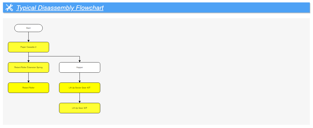
Disassembly Flowchart
 Check Point / チェックポイント Check Point / チェックポイント |
|
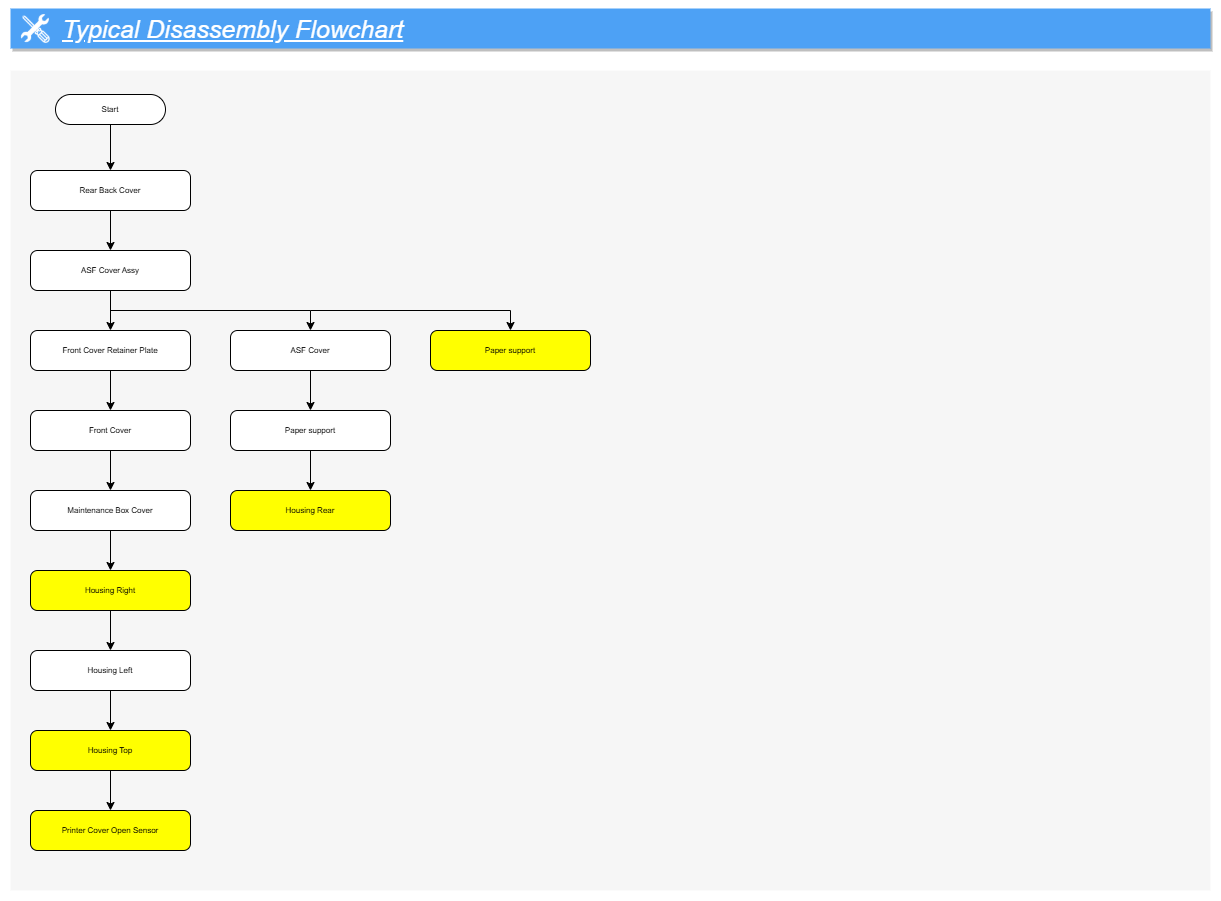
Housing (WF-C579R) (1/2)
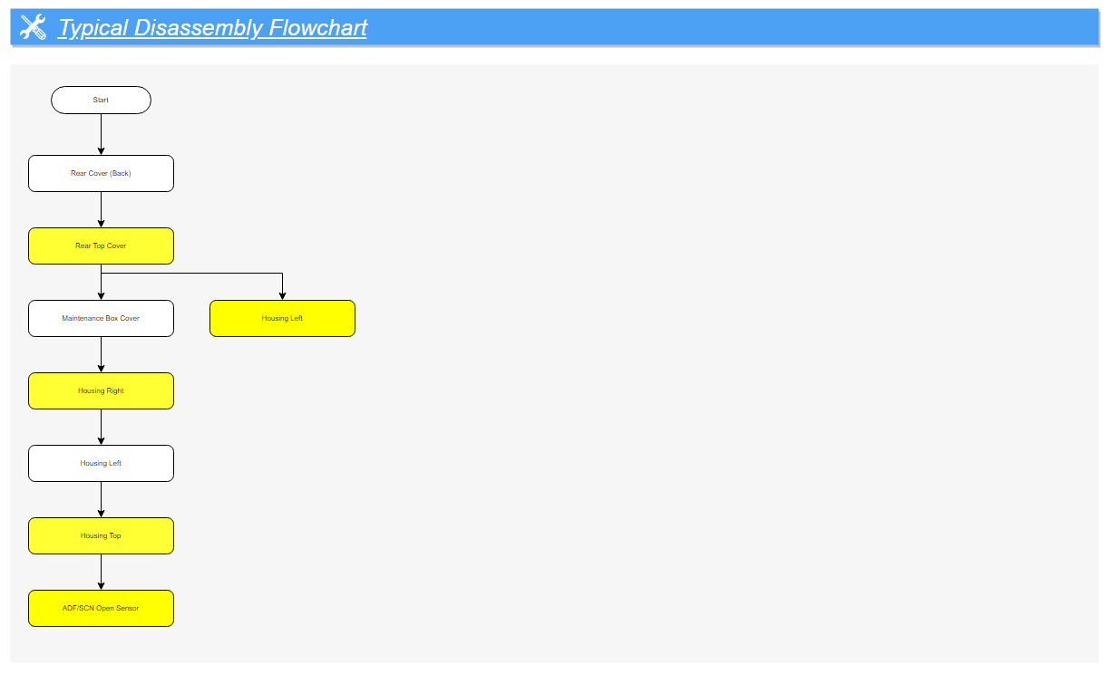
Housing (WF-C579R) (2/2)
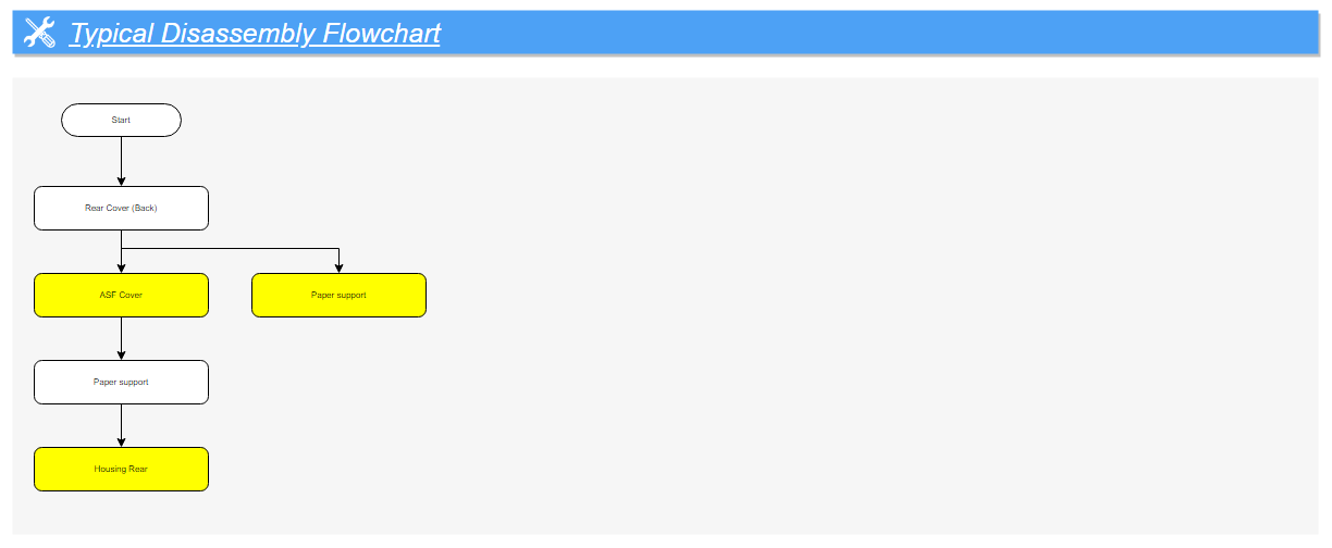
Housing (WF-C529R) (1/2)
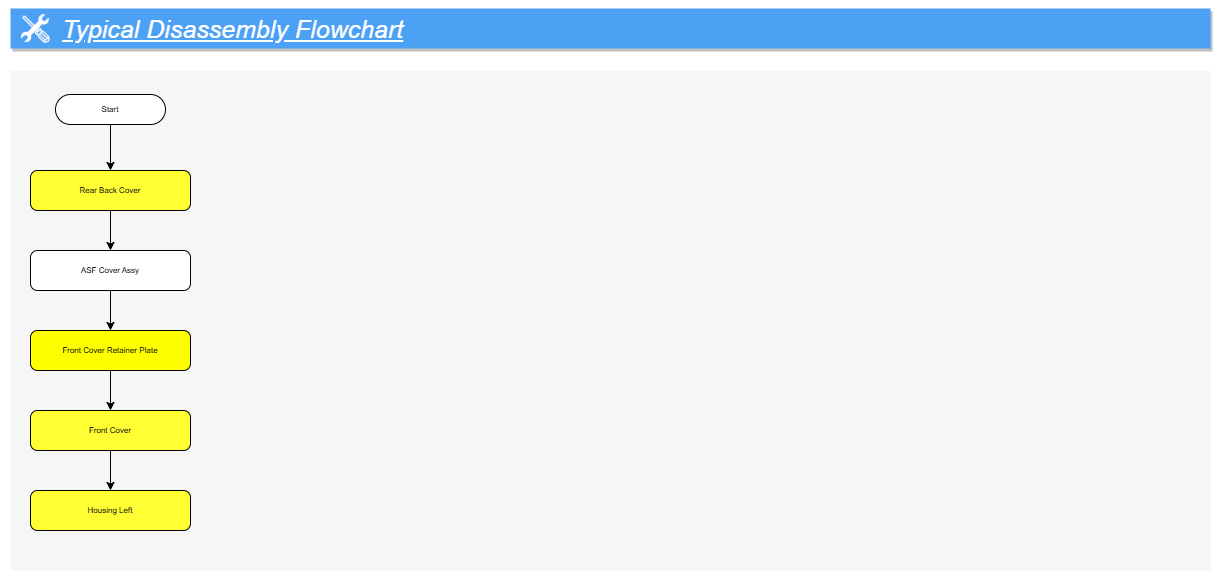
Housing (WF-C529R) (2/2)
Ink Supply Mechanism (1/3)
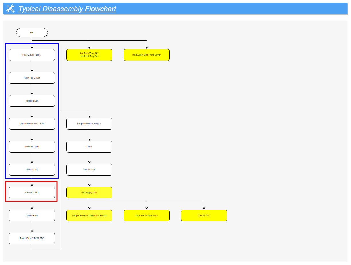
Ink Supply Mechanism (2/3)
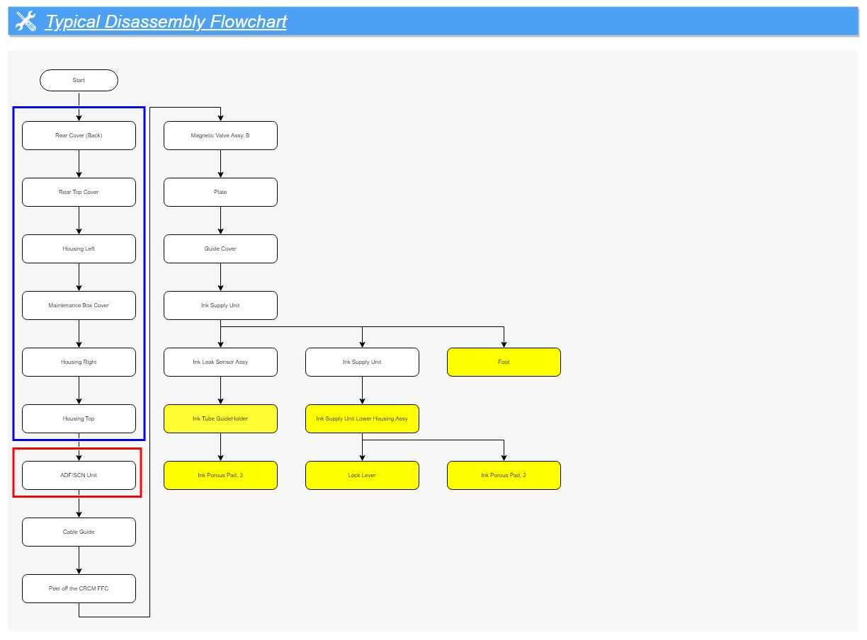
Ink Supply Mechanism (3/3)
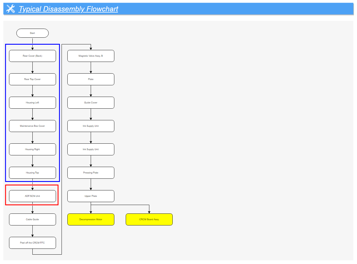
ADF/SCN (WF-C579R only) (1/2)
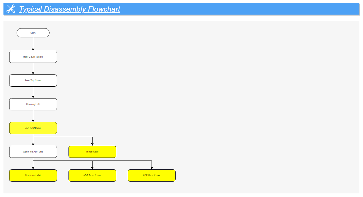
ADF/SCN (WF-C579R only) (2/2)
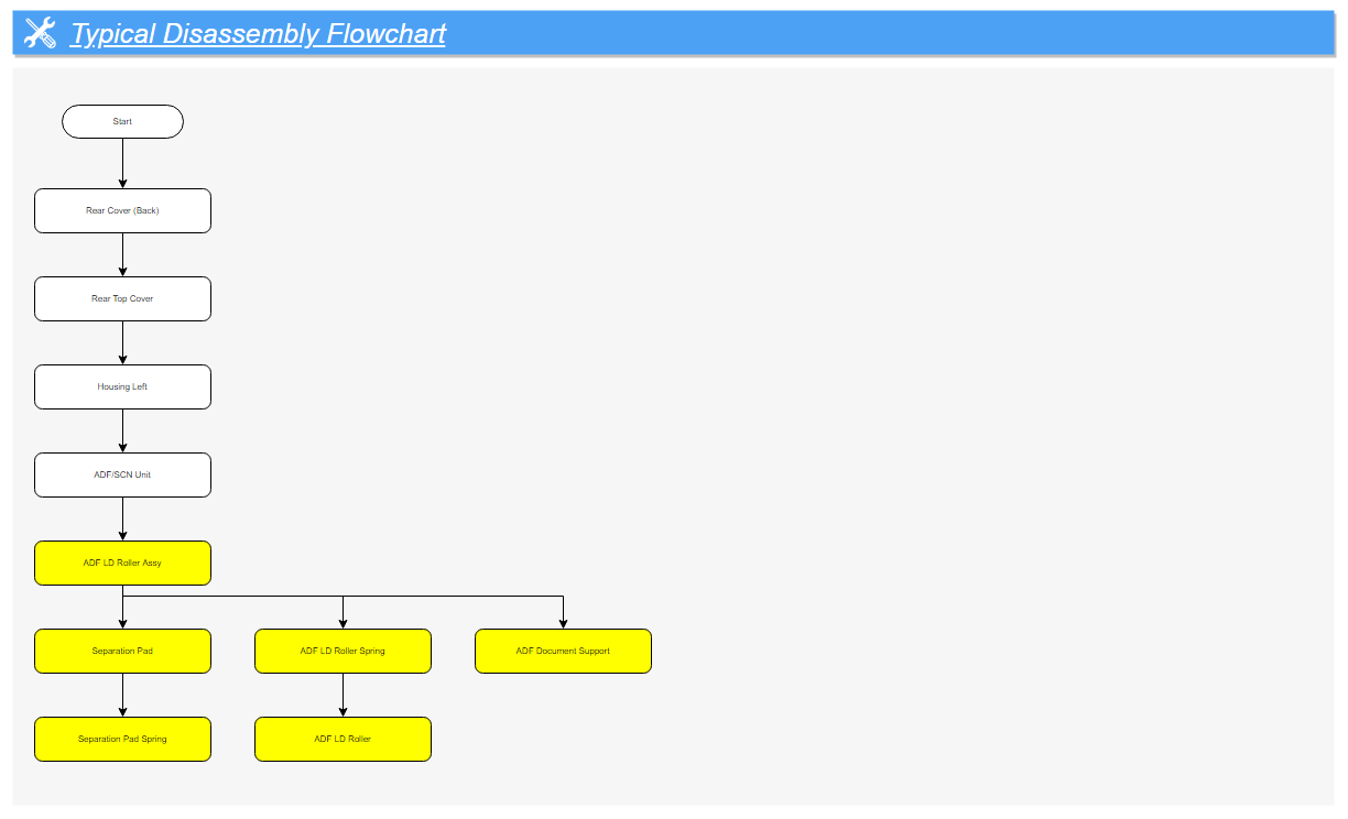
Electric Circuit Components (1/2)
| Check Point / チェックポイント |
|
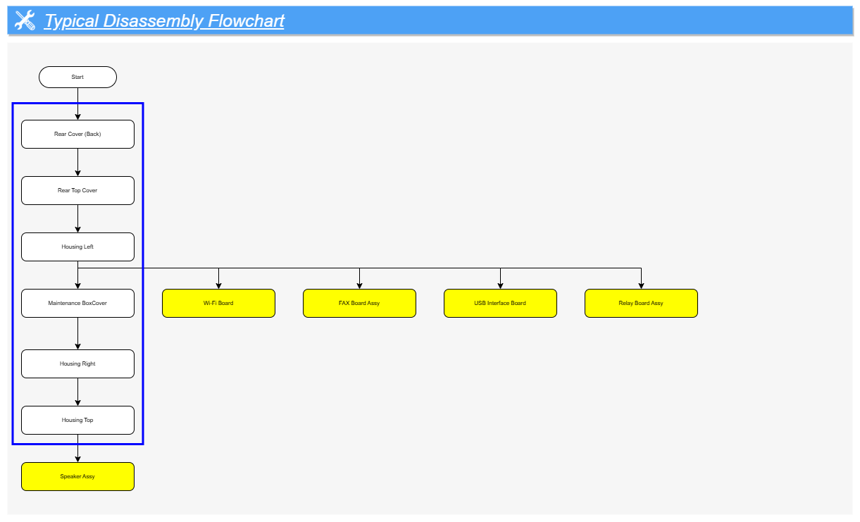
Electric Circuit Components (2/2)
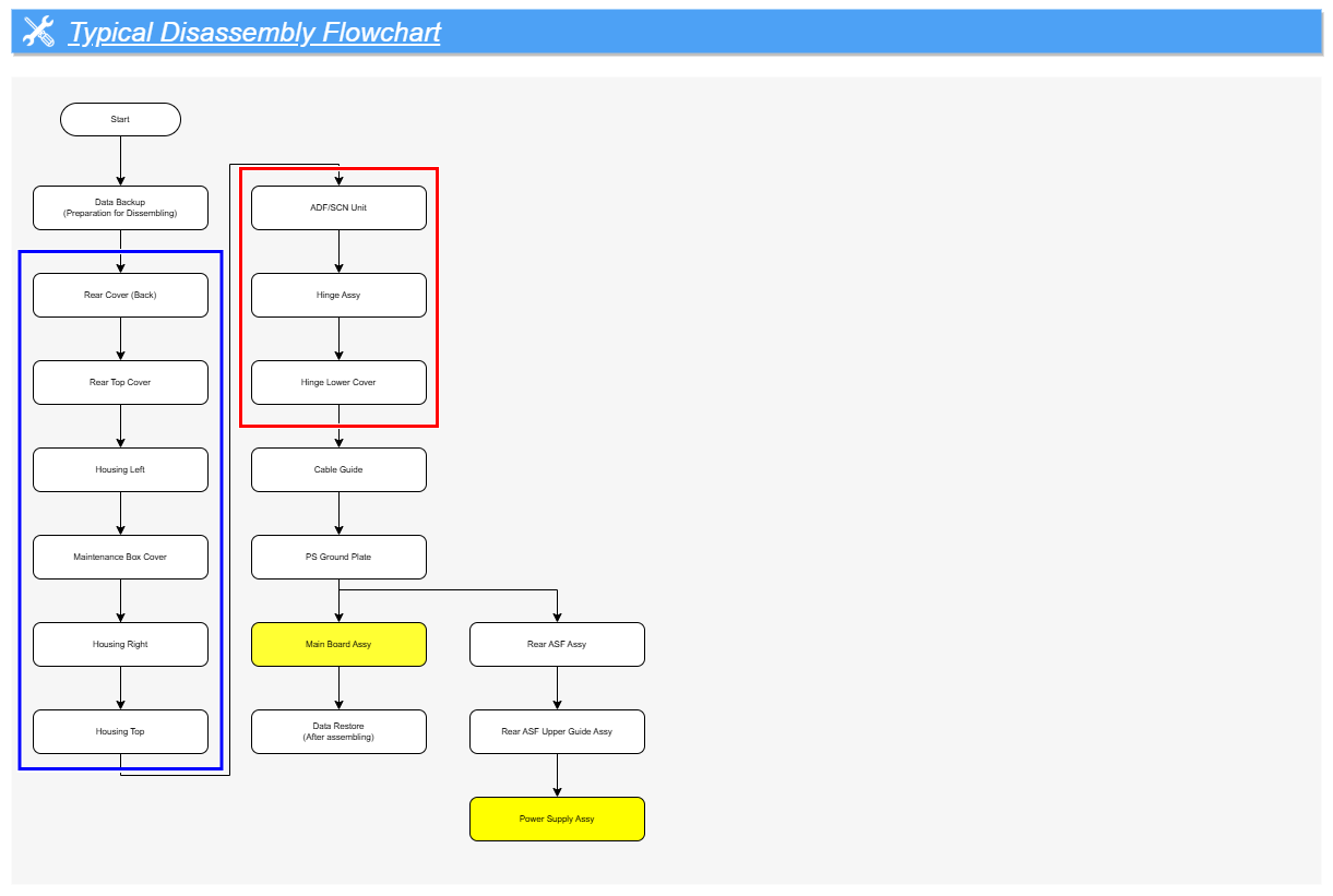
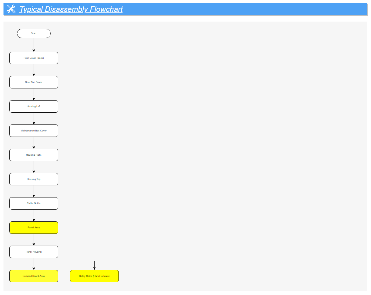
Electric Circuit Components (WF-C579R) (1/1)
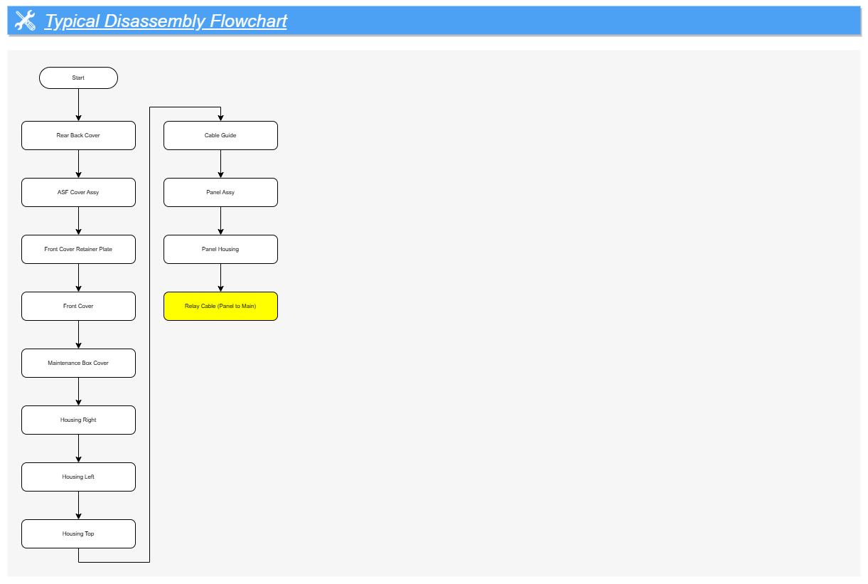
Electric Circuit Components (WF-C529R) (1/1)
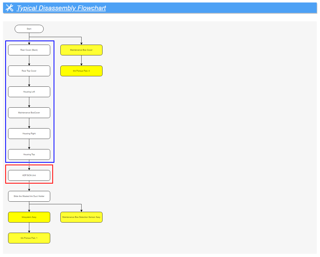
Inksystem (1/1)
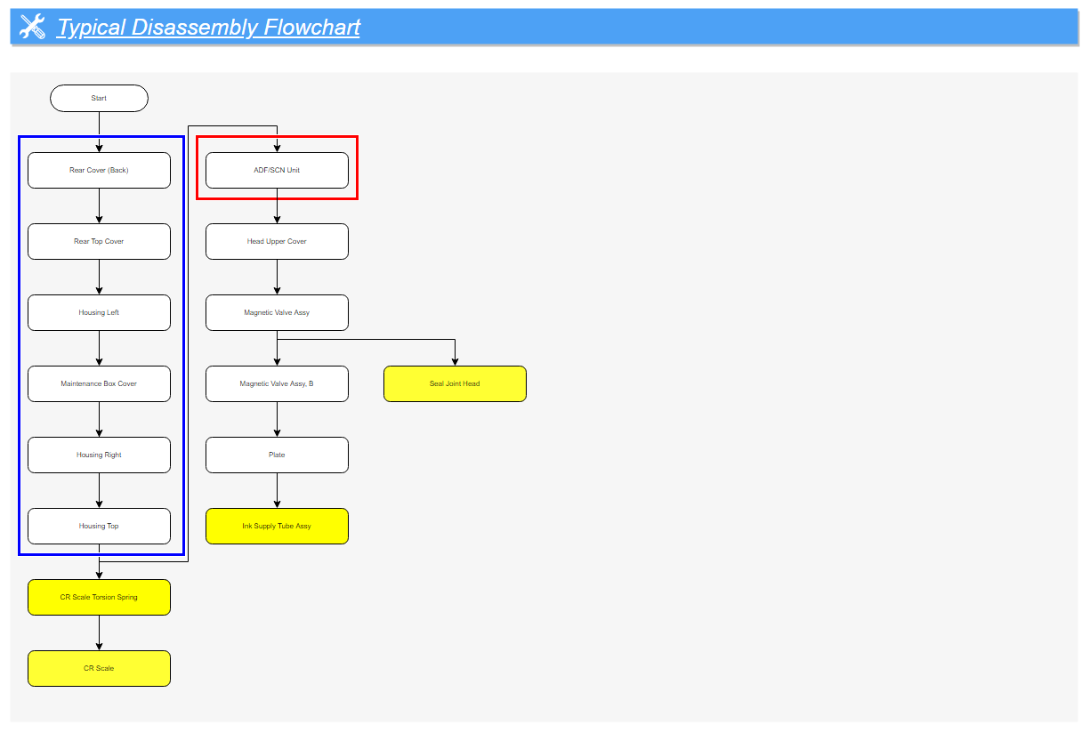
Carriage Mechanism (1/3)
Carriage Mechanism (2/3)
| Check Point / チェックポイント |
Perform B90 PRINTHEAD (PREPARATION BEFORE REPLACEMENT) before removing Print head. |
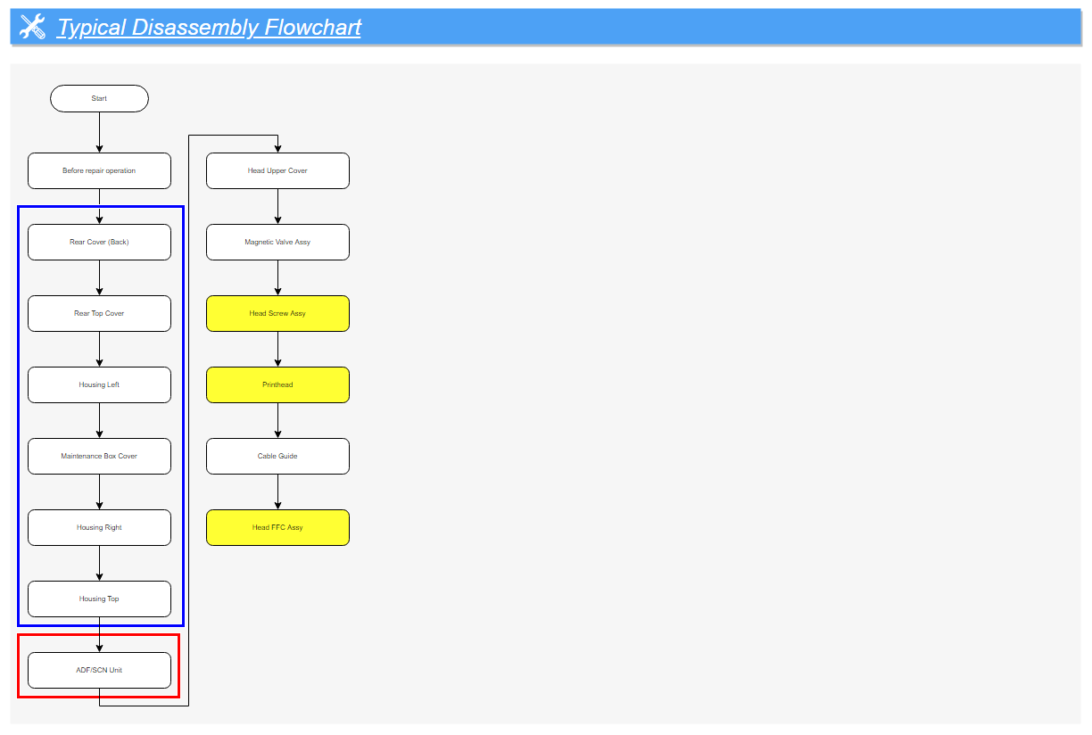
Carriage Mechanism (3/3)
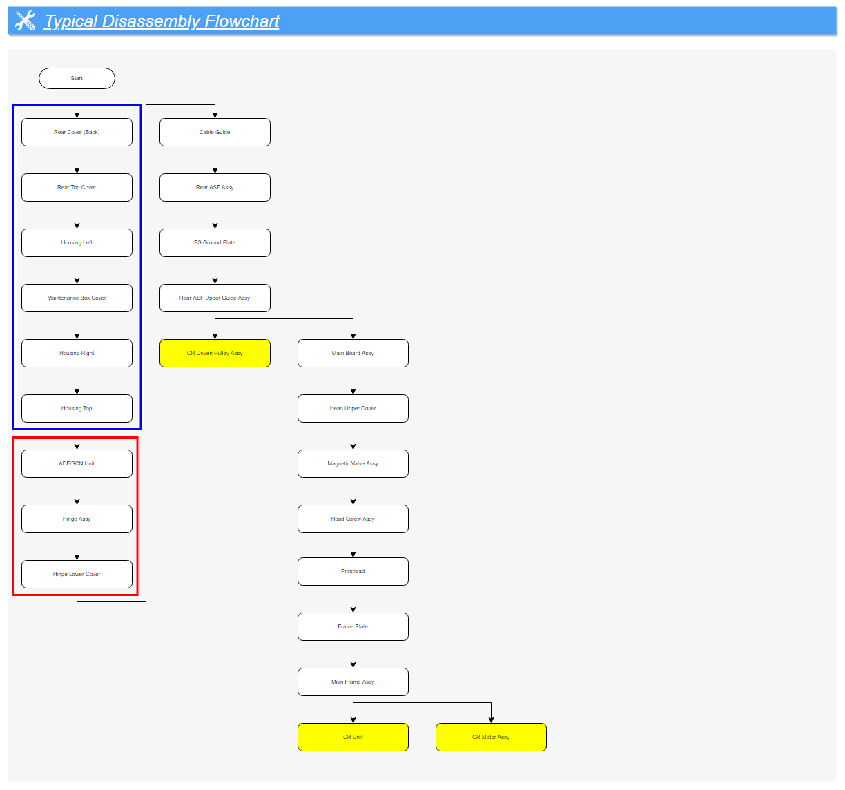
Paper Feed Mechanism (1/6)
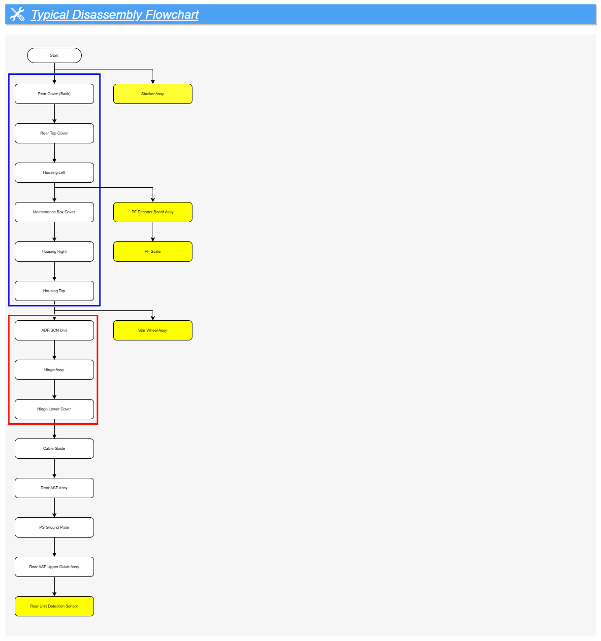
Paper Feed Mechanism (2/6)
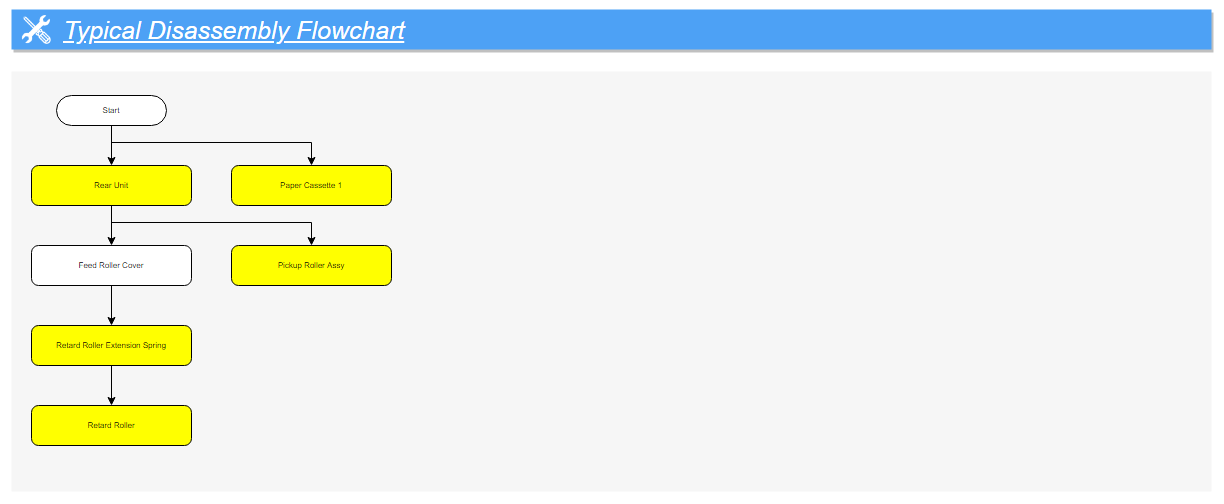
Paper Feed Mechanism (3/6)
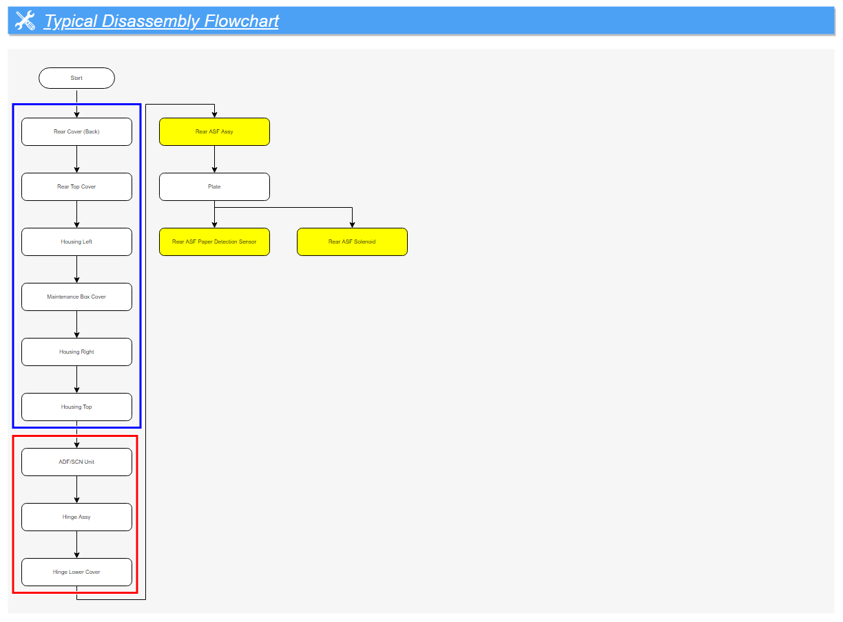
Paper Feed Mechanism (4/6)
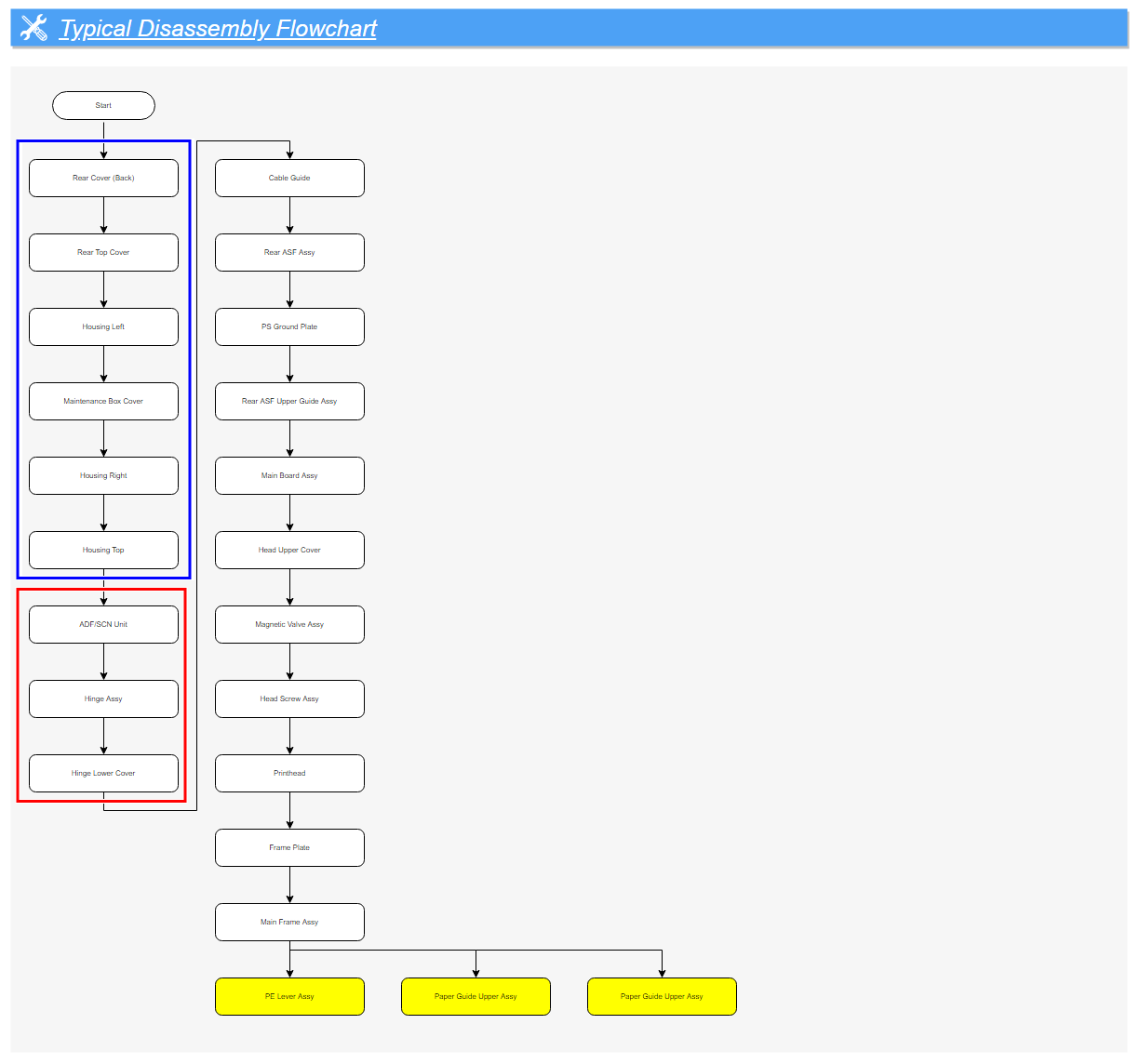
Paper Feed Mechanism (5/6)
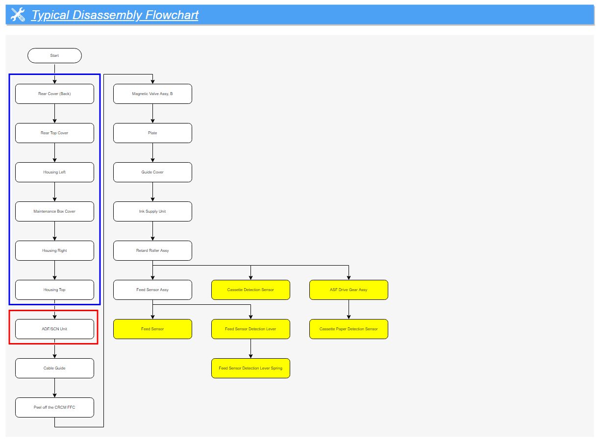
Paper Feed Mechanism (6/6)
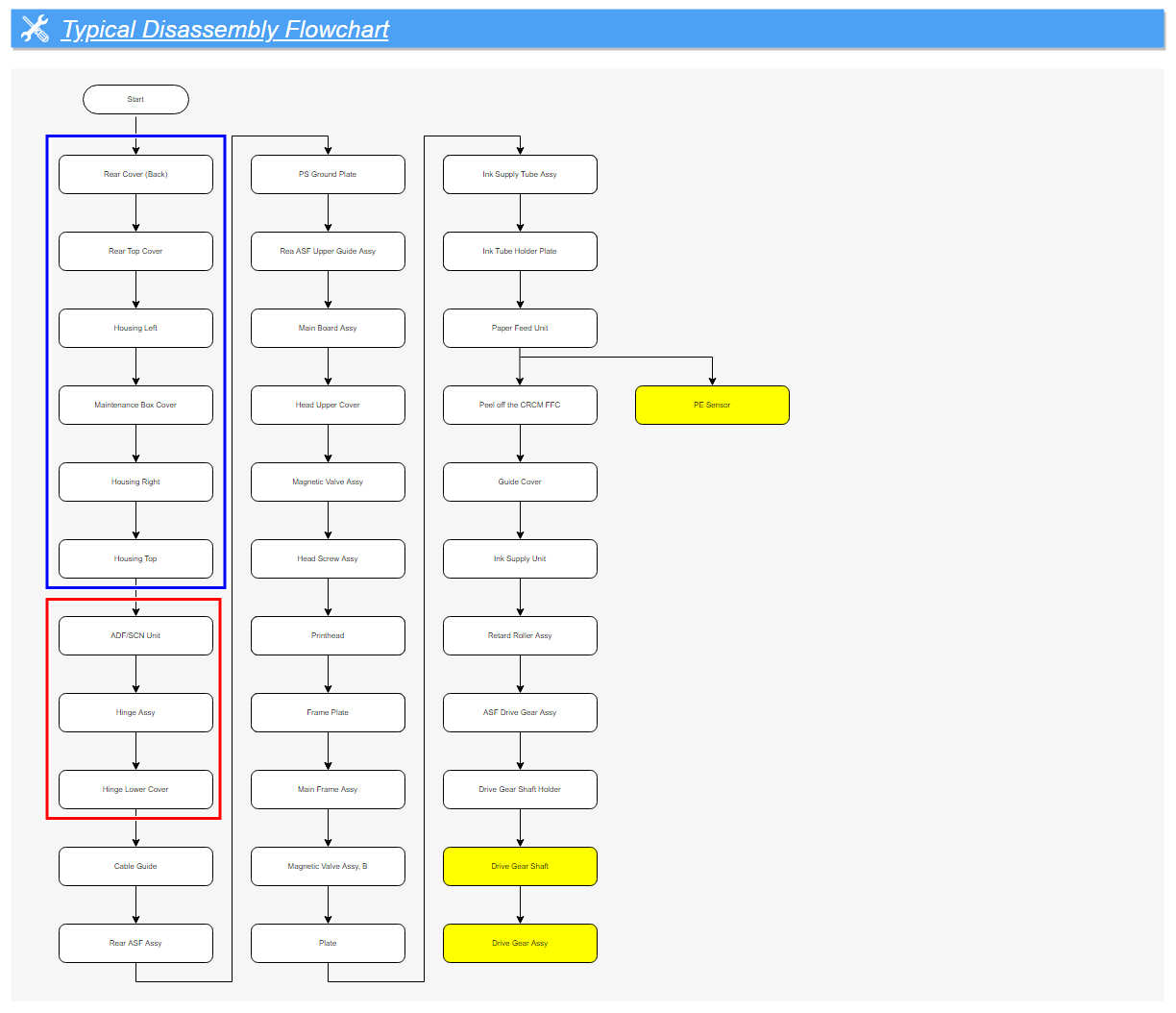
Optional Paper Cassette Unit (1/5)
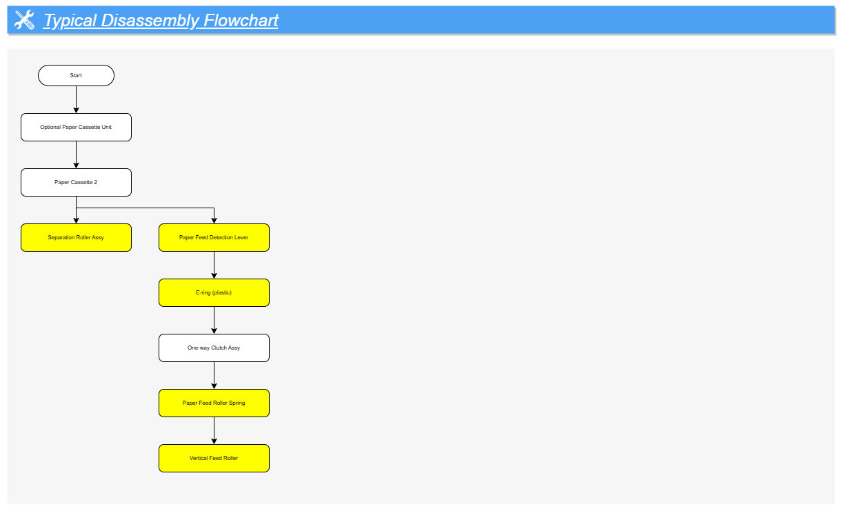
Optional Paper Cassette Unit (2/5)
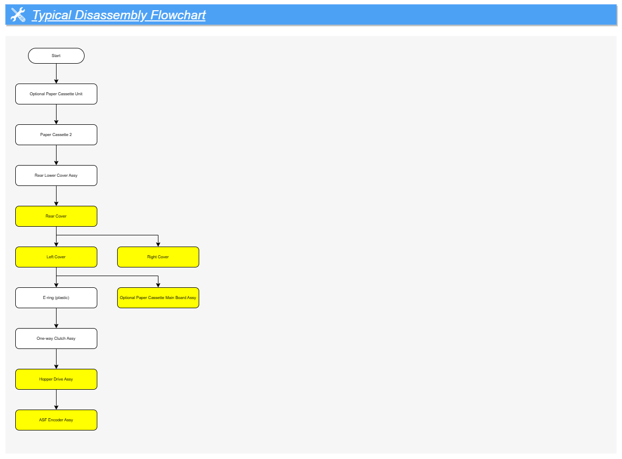
Optional Paper Cassette Unit (3/5)
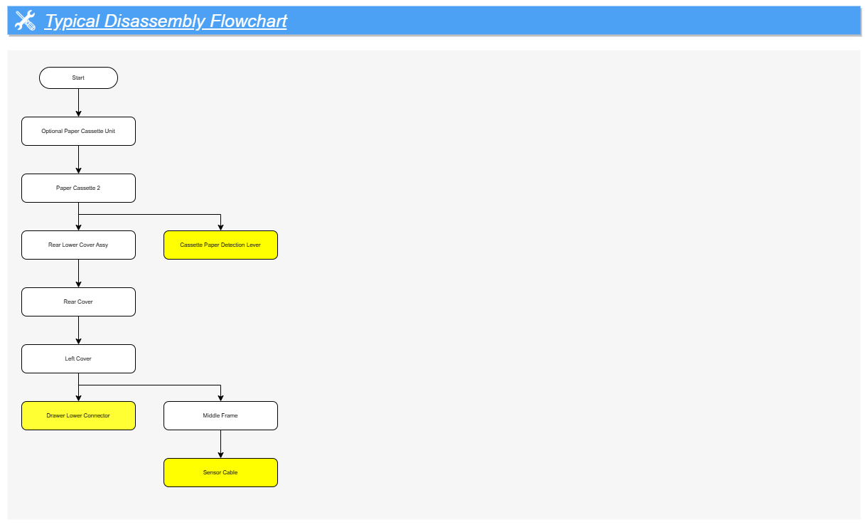
Optional Paper Cassette Unit (4/5)
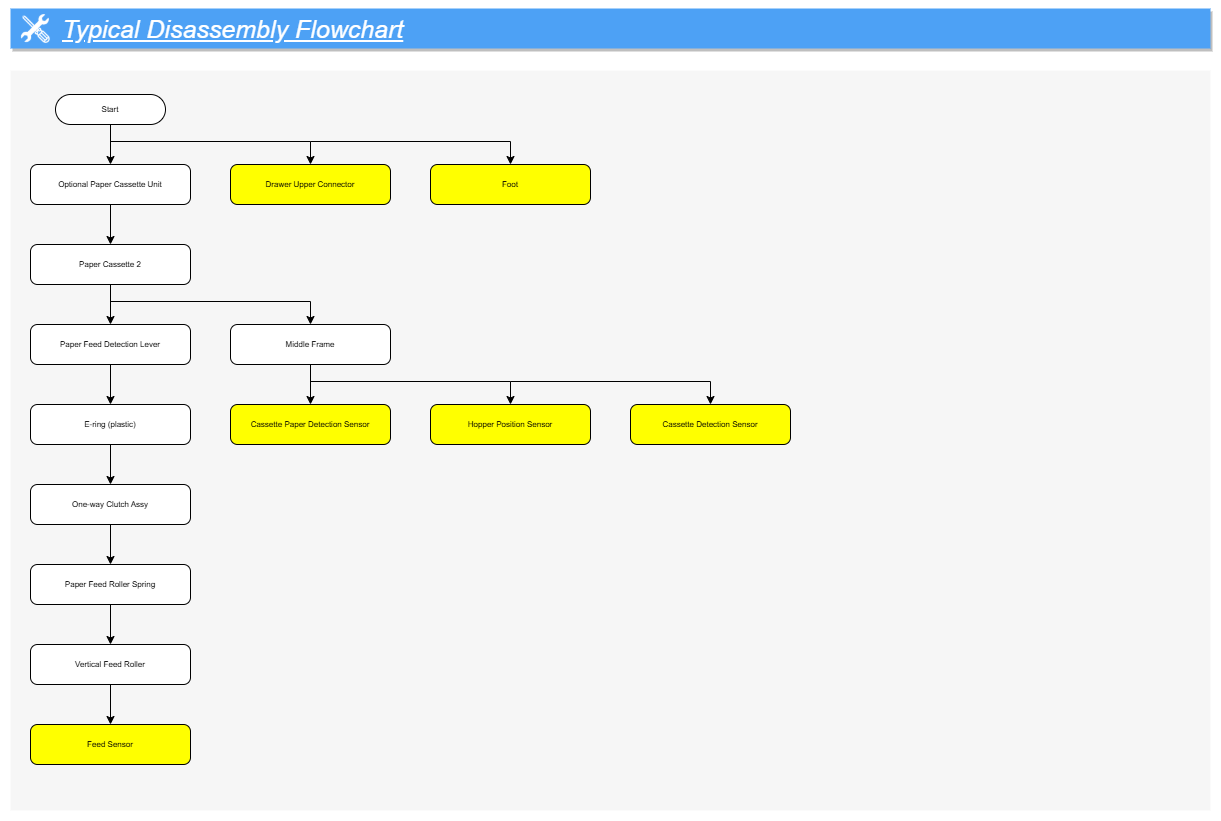
Optional Paper Cassette Unit (5/5)