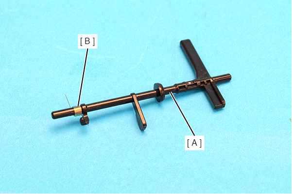
Feed Sensor Detection Lever Spring (WF-C529R Series)
- Remove the Rear Unit (A).
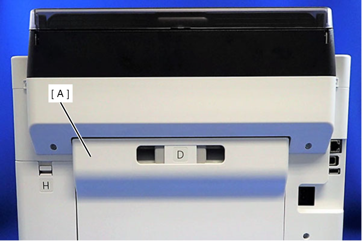
- Remove the two screws that secure the ASF Cover Assy (A).
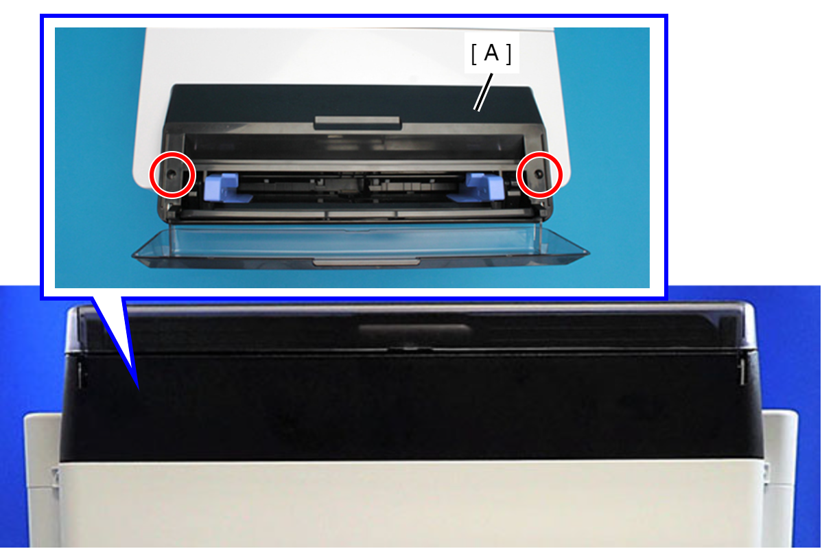
 : C.B.P-TITE-SCREW-3x10-F.ZN-3C
- Remove the four screws that secure the Rear Back Cover (A).
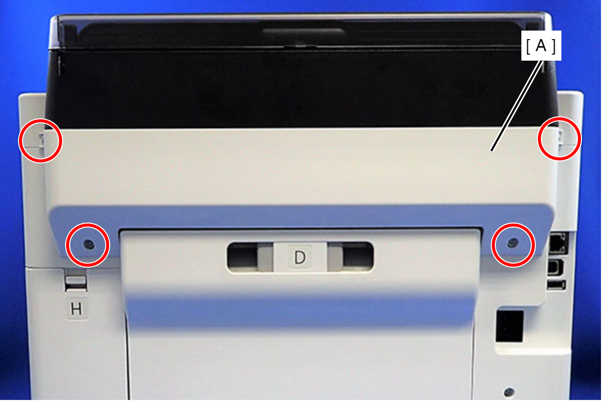
 : C.B.P-TITE-SCREW-3x10-F.ZN-3C
- Remove the Rear Back Cover (A) downward.
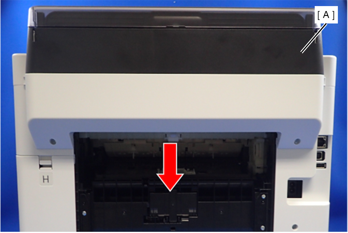
 Assembly / 組み立て
Attach the two dowels of the Rear Back Cover (A) to the positioning holes on the Housing Left (B) and the Housing Right (C).
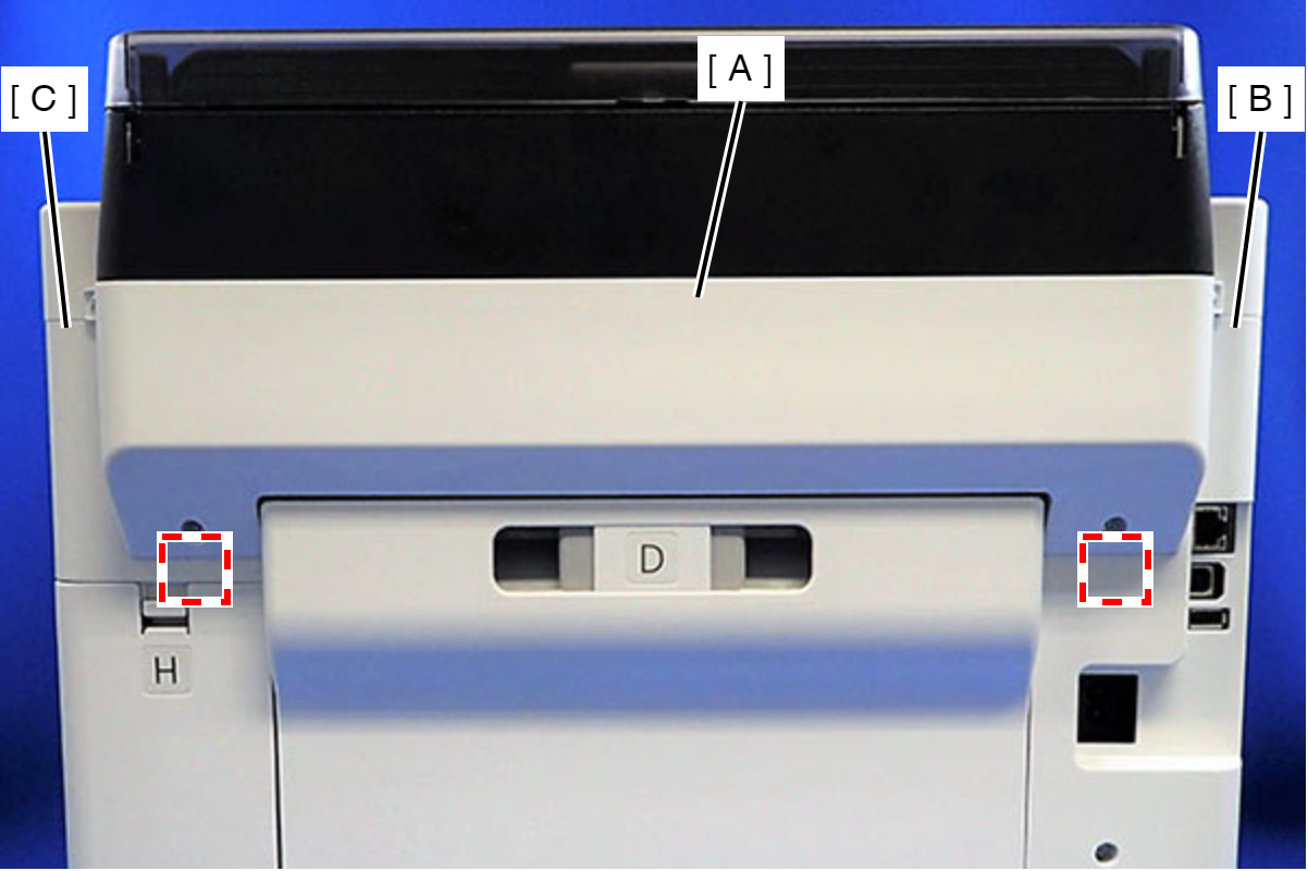
- Remove the ASF Cover Assy (A) in the direction of the arrow.
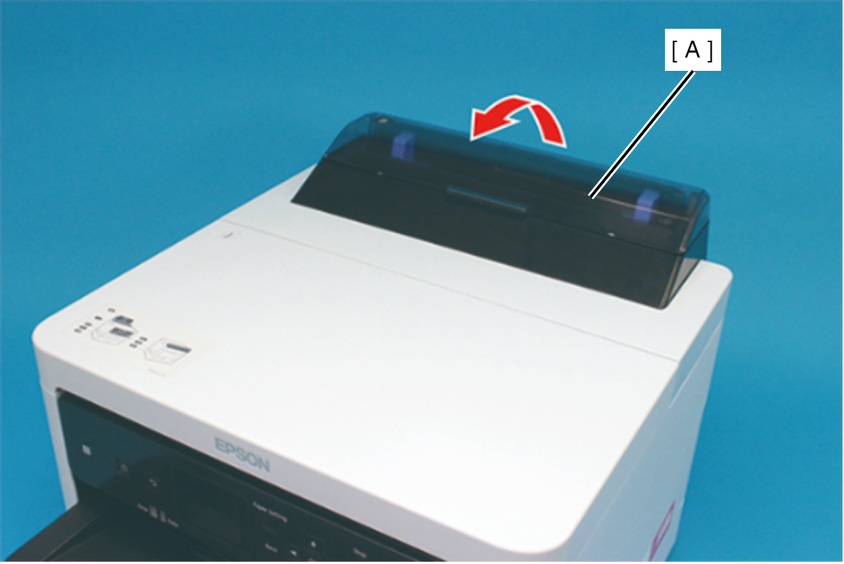
Assembly / 組み立てInsert the four tabs of the ASF Cover Assy (A) to the positioning holes of the Front Cover Retainer Plate.
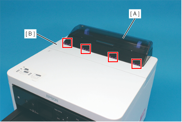
- Remove the two screws securing the Front Cover Retainer Plate (A).
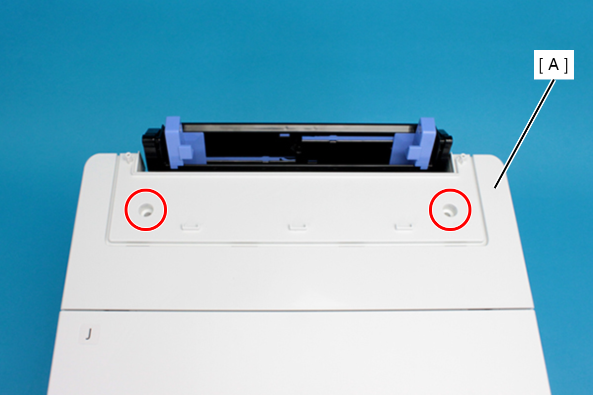
- : C.B.P-TITE-SCREW-3x10-F/ZN-3C
- Open the Printer Cover (A) and remove the four screws, and then remove the Front Cover Retainer Plate (B).
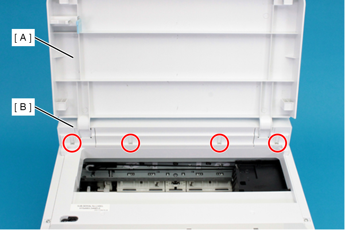
- : C.B.P-TITE-SCREW-3x10-F/ZN-3C
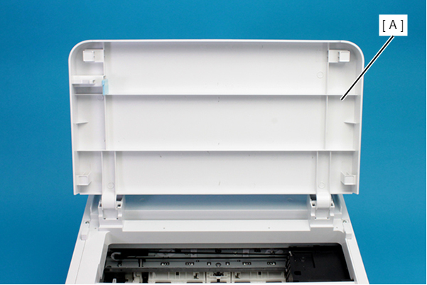
- Remove the Front Cover (A) upward.
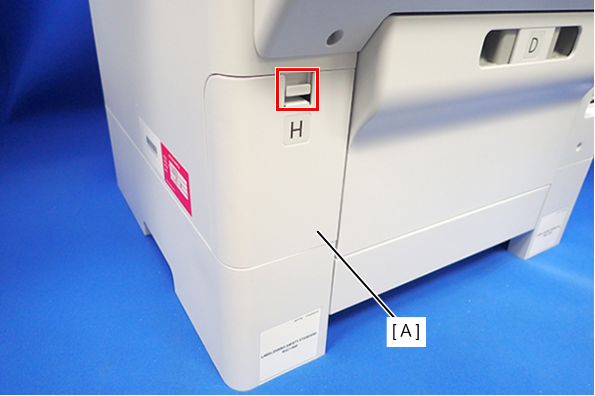
- Disengage the hook, and remove the Maintenance Box Cover (A).
- Remove the three screws that secure the Housing Right (A).
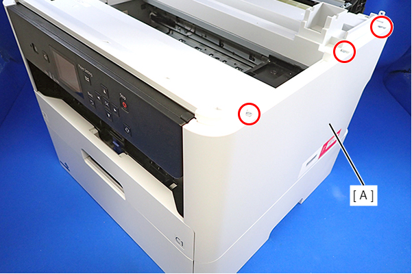
- : C.B.P-TITE-SCREW-3x10-F.ZN-3C
- Remove the two screws that secure the Housing Right (A).
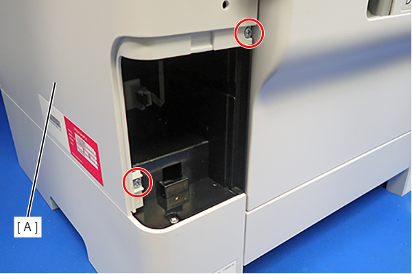
- : C.B.P-TITE-SCREW-3x10-F.ZN-3C
- Lift the Housing Right (A) to release the two hooks on the front side of the Housing Right (A), then remove the Housing Right (A).
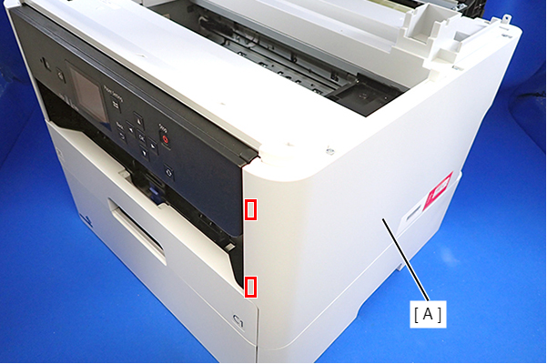 Assembly / 組み立て
Insert the four tabs of the Housing Right (A) to the positioning holes on the Ink Supply Unit (B).
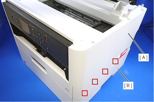
- Remove the three screws that secure the Housing Left (A).
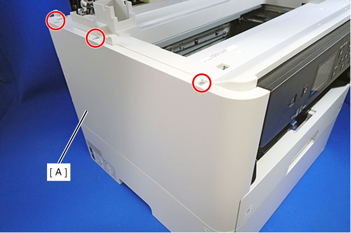
- : C.B.P-TITE-SCREW-3x10-F.ZN-3C
- Remove the two screws that secure the Housing Left (A).
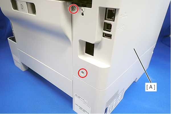
- : C.B.P-TITE-SCREW-3x10-F.ZN-3C
- Lift the Housing Left (A) to release the two hooks each on the front side and rear side of the Housing Left (A), and then remove the Housing Left (A).
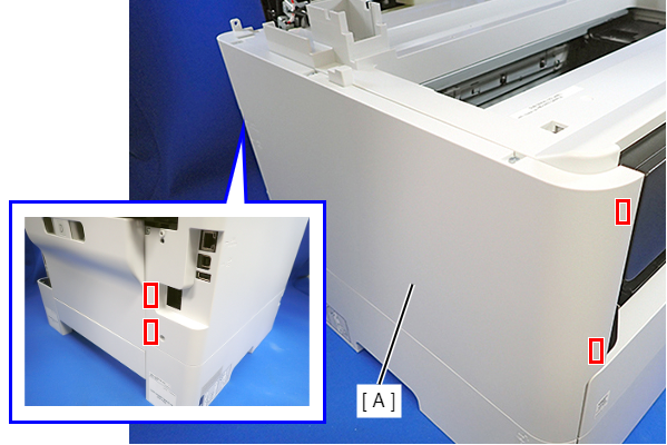 Assembly / 組み立て
Insert the four tabs on the Housing Left (A) to the positioning holes of the Ink Supply Unit (B).
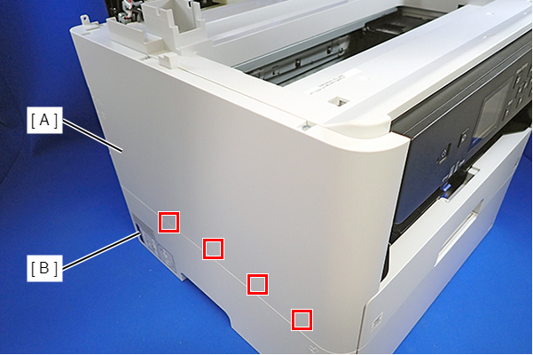
- Remove the six screws, then remove the Housing Upper (A).
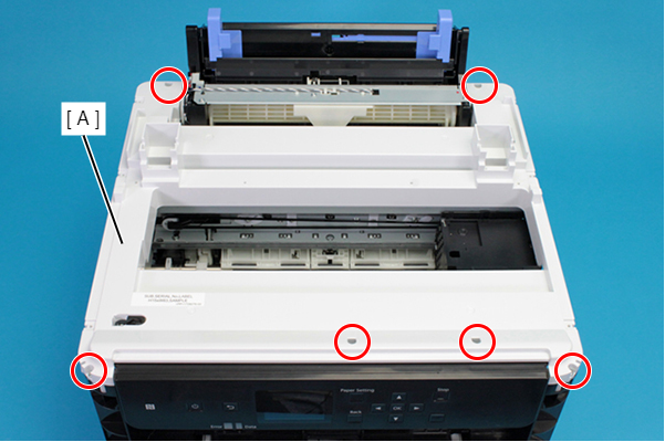
- : C.B.P-TITE-SCREW-3x10-F.ZN-3C
- Release the all cable from the Cable Guide (A).
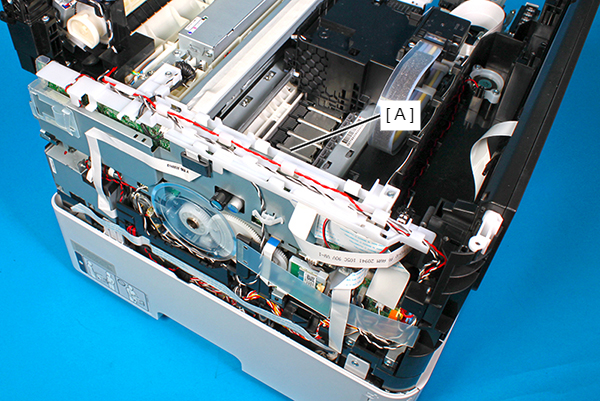
- Remove the two screws, and remove the Cable Guide (A).
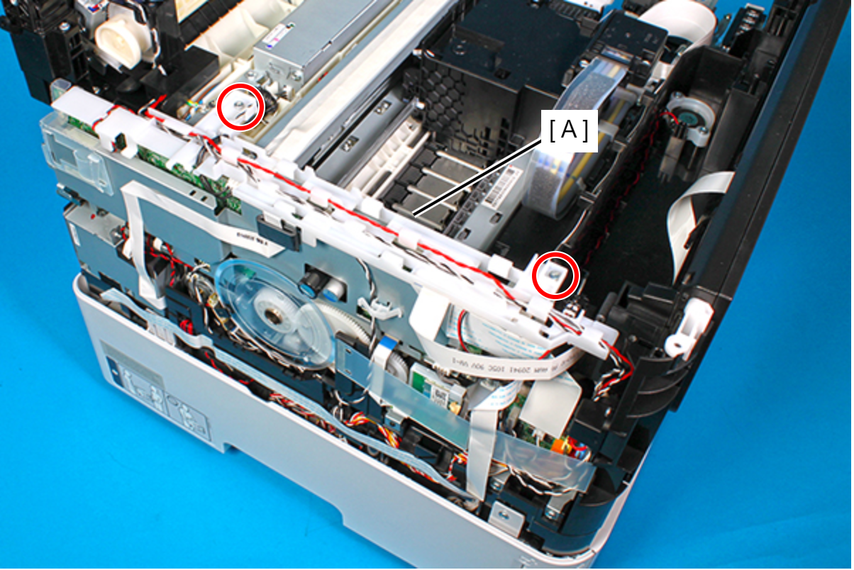
- : C.B.P-TITE-SCREW-3x10-F.ZN-3C
Assembly / 組み立て- Route the PS cable (A) through the two guides and hook on the Cable Guide.
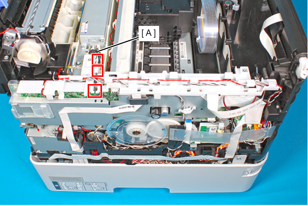
- Route the Rear ASF Solenoid cable (A) through the six hooks on the Cable Guide.
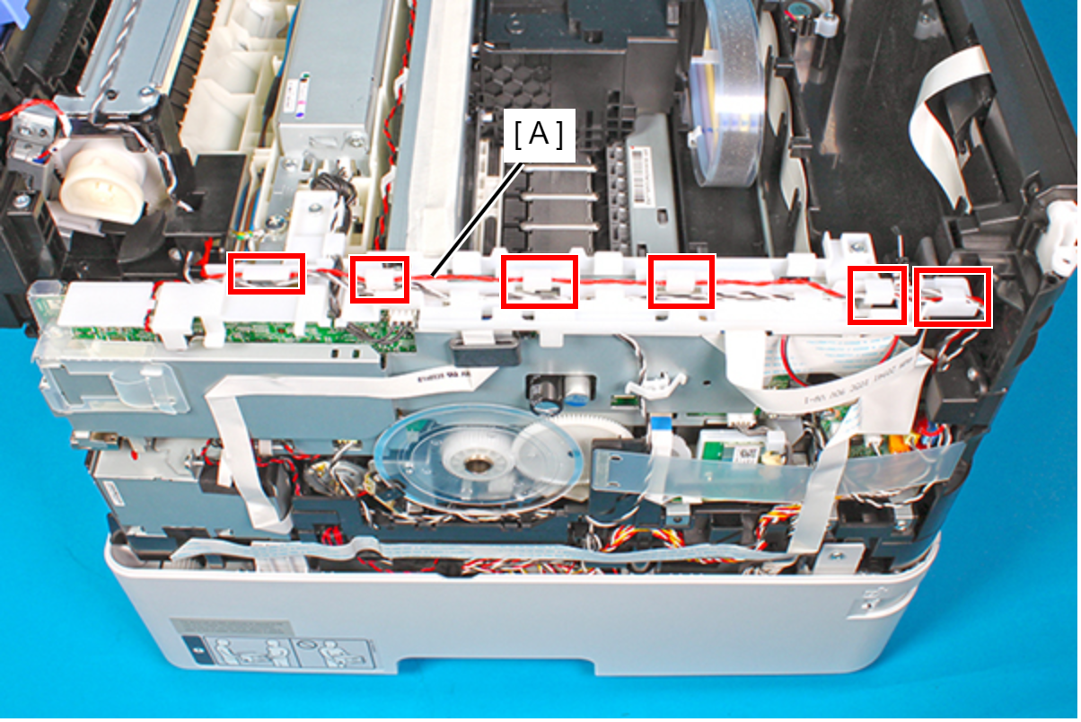
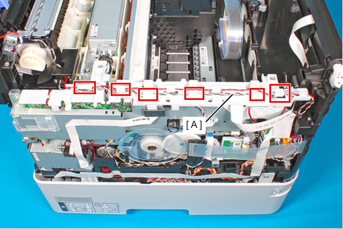
- Route the Rear Unit Detection Sensor cable and Rear ASF Paper Detection Sensor cable (A) through the three hooks and the three hooks on the Cable Guide.
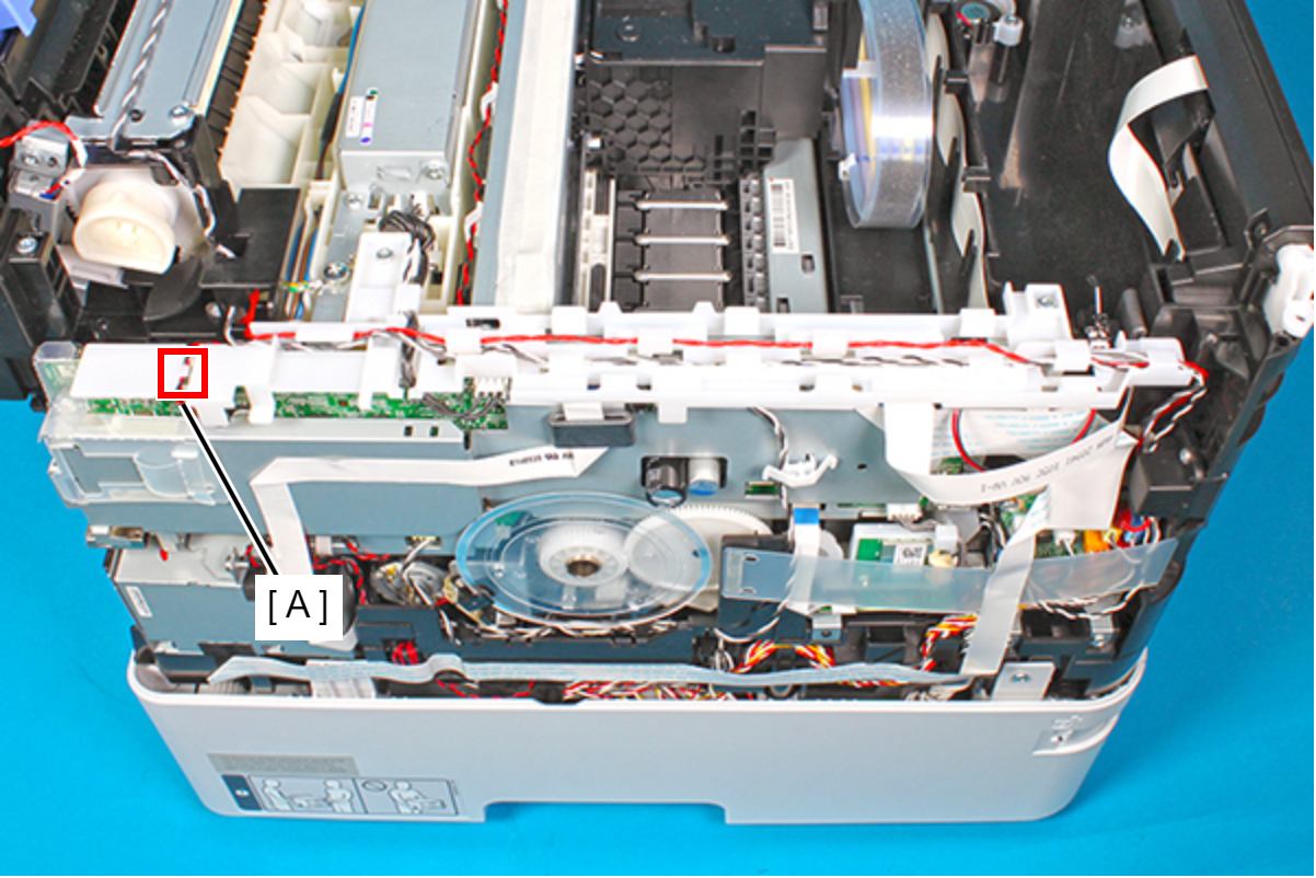
- Route the ASF motor cable (A) through the guide on the Cable Guide.
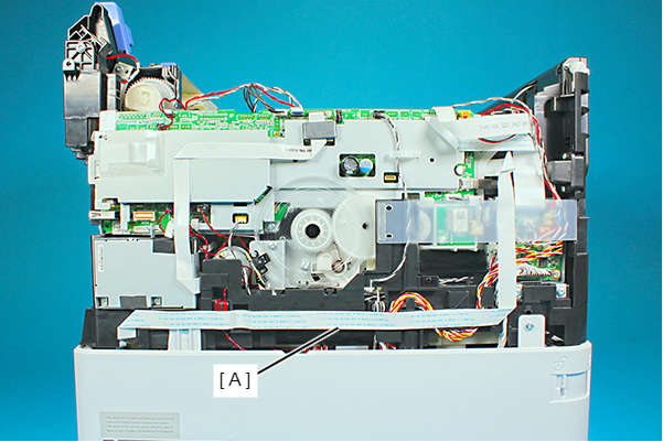
- Peel off the CRCM FFC (A).
- Peel off the CRCR FFC Sheet (A).
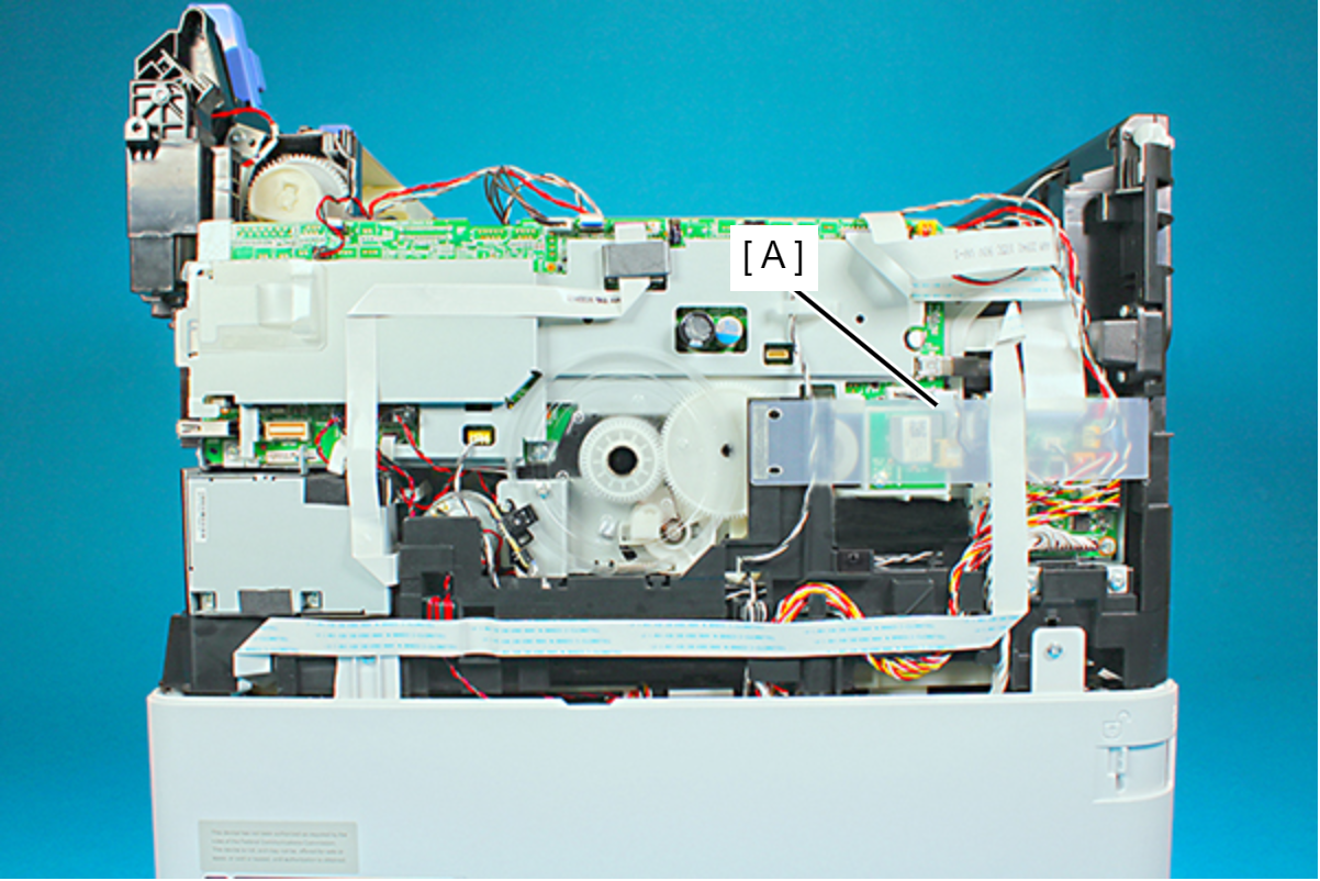
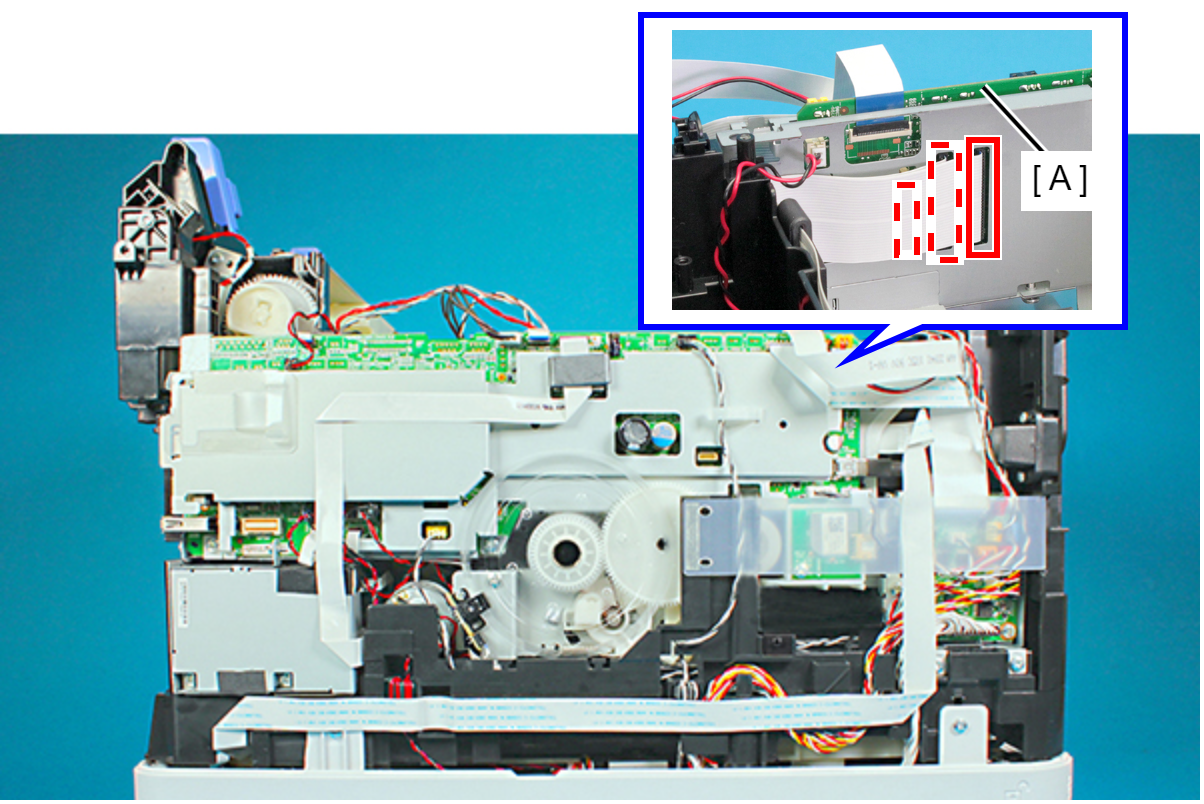
- Disconnect the FFCs (CN67,CN66, CN68) from the Main Board (A).
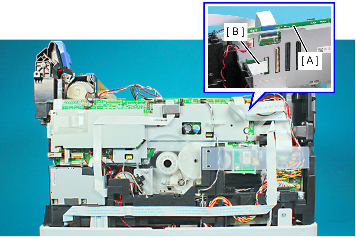
- Disconnect the CRCM FFC (B) from the Main Board (A).
- Remove the screw, then remove the Magnetic Valve Assy B (A).
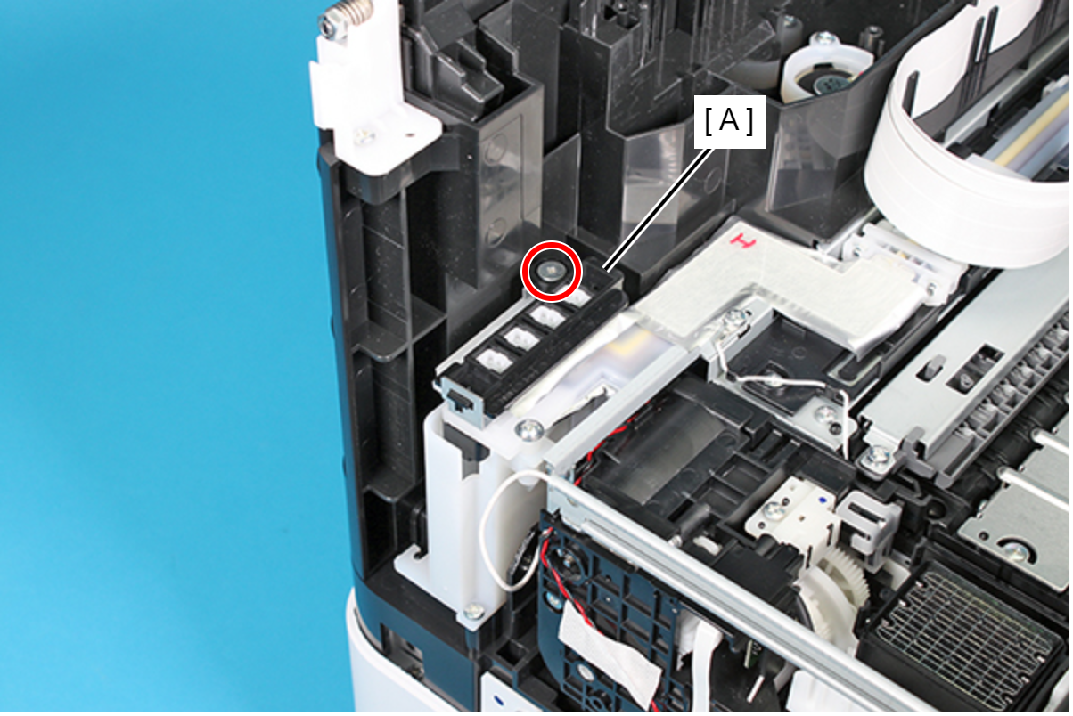
- : SCREW, JOINT, HEAD
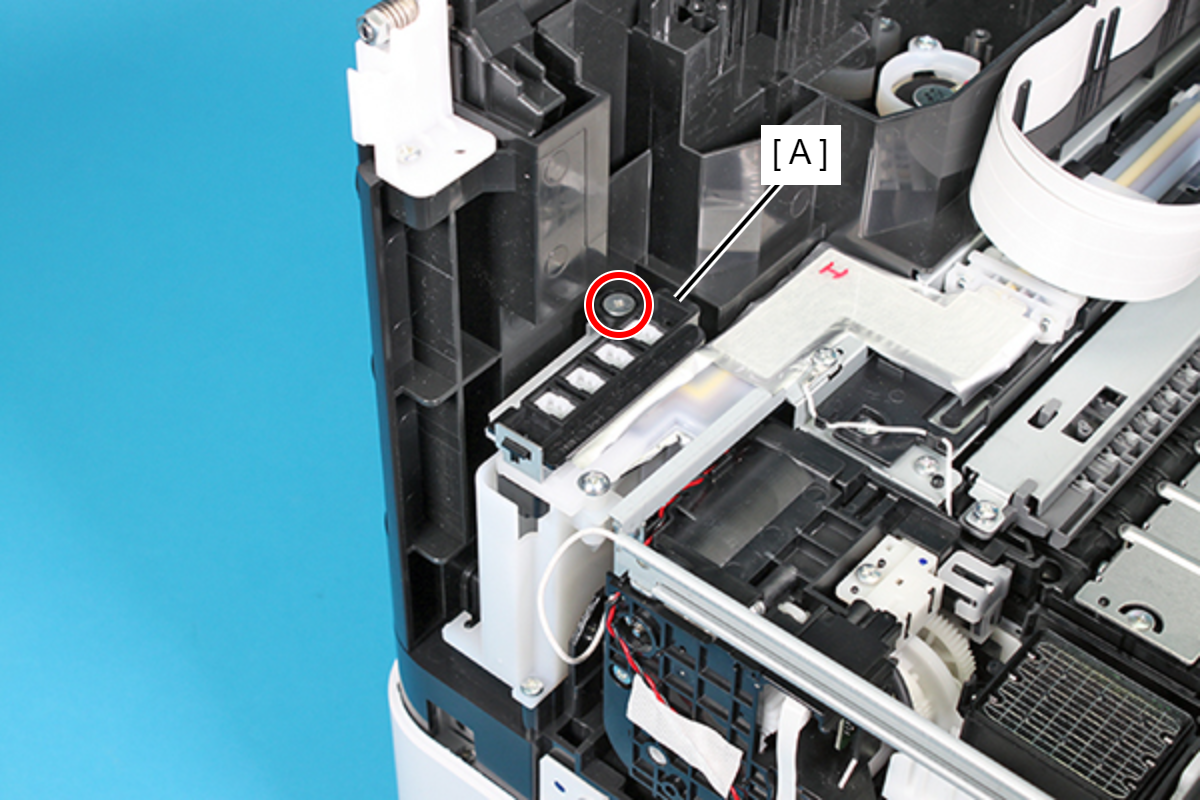
Assembly / 組み立て- When attaching the Magnetic Valve Assy, B (A), make sure to align the rib with the hole on the plate.
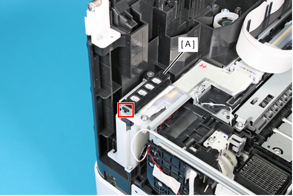
- Make sure the Magnetic Valve Assy, B (A) is secured with the screw.
- Remove the two screws and then remove the plate (A).
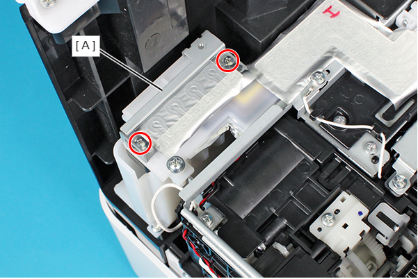
- : C.B.(S-P1)SCREW,2.5X18,F/ZN-3C
Assembly / 組み立て- When installing the Ink Supply Tube (A) to the Ink Supply Unit Assy, make sure to tighten the screws using a torque driver with the specified torque.
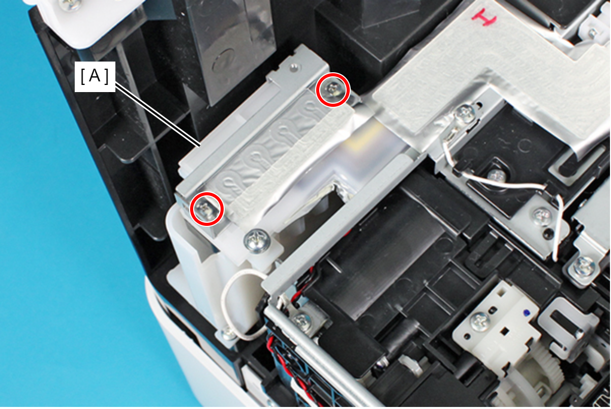
- Screw tightening torque: 0.25 ± 0.03N×m
- The S6 screw (A) and the Hexagon nut (H.N.-1,2.5,F/ZN-3C) is supplied as ASP.
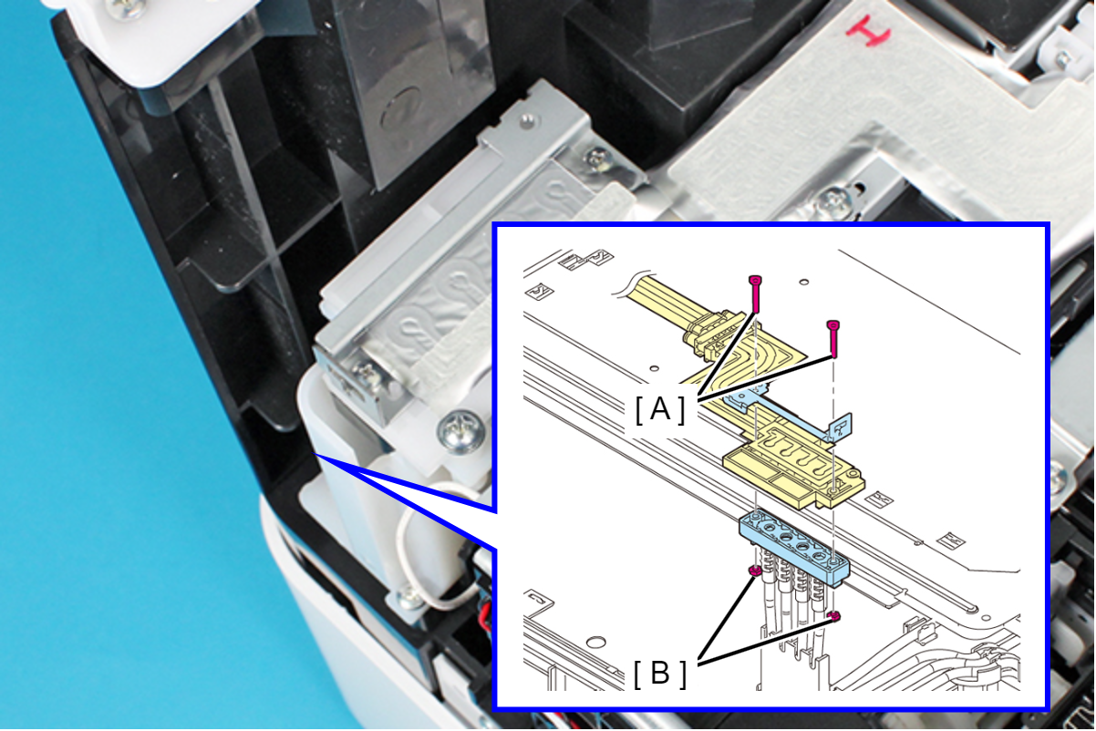
- When attaching the plate (A), make sure to align the dowel on the Ink Supply Tube Assy (B) and the positioning hole on the plate.
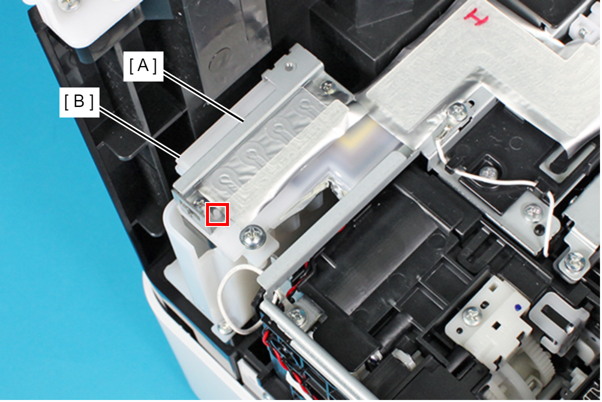
- Remove the two screws, and remove the Guide Cover (A) in the direction of the arrow.
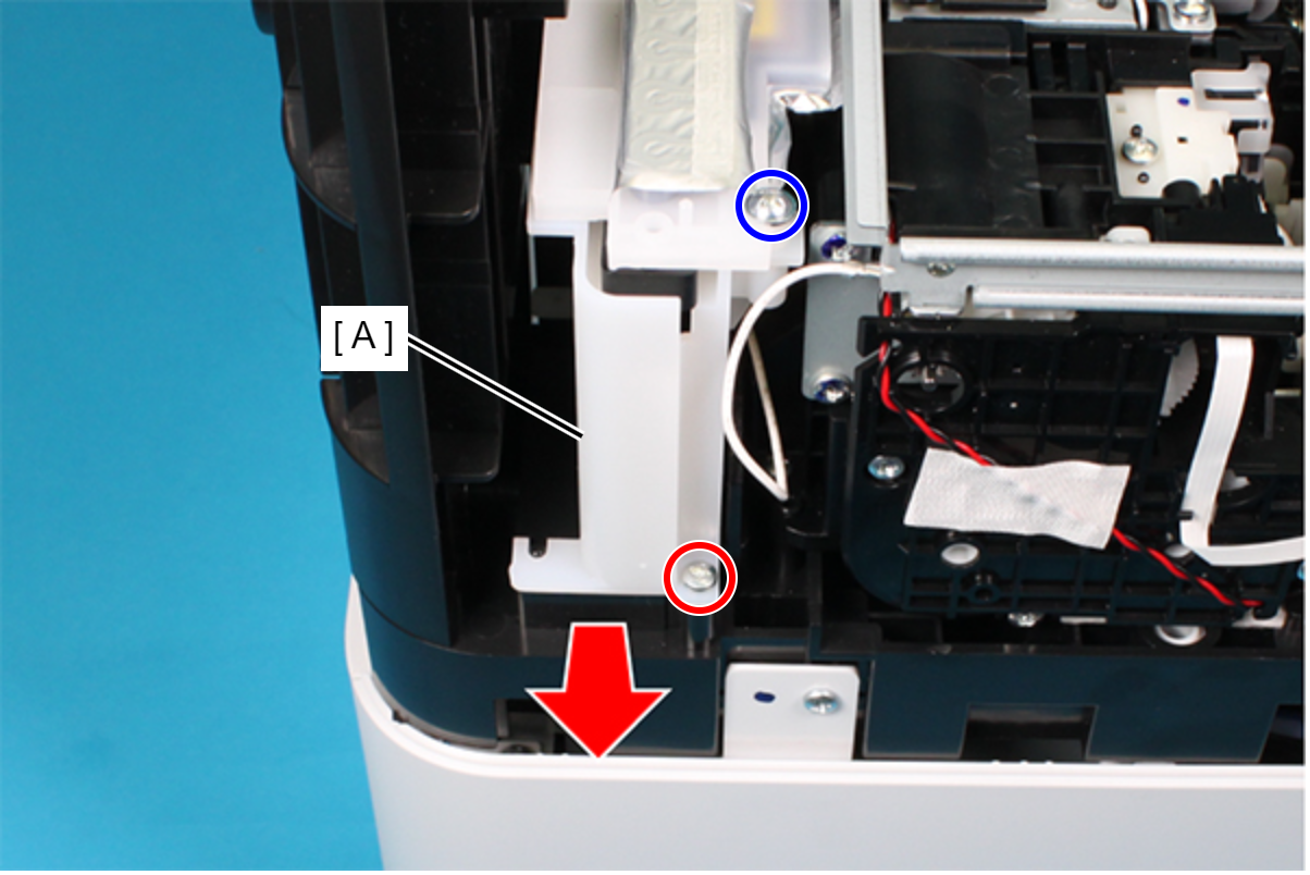
- : C.B.P-TITE-SCREW-3x10-F.ZN-3C
 : C.C.P-TITE-SCREW-3x12-F.ZN-3C
- Disconnect the cables from the connectors (CN2, CN10, CN11, CN12, CN22, CN30, CN31, CN54, CN55) on the Relay Board (A).
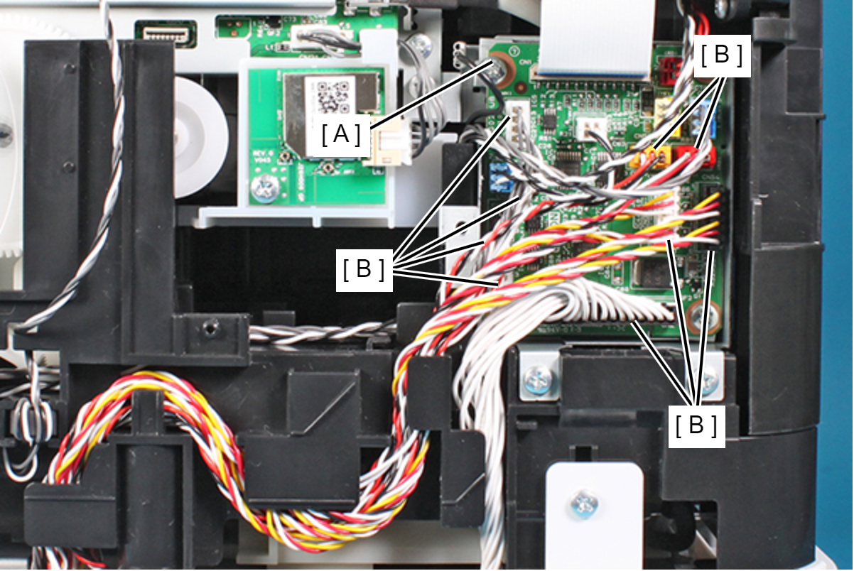
- Release the cables from the five tabs on the Frame Base.
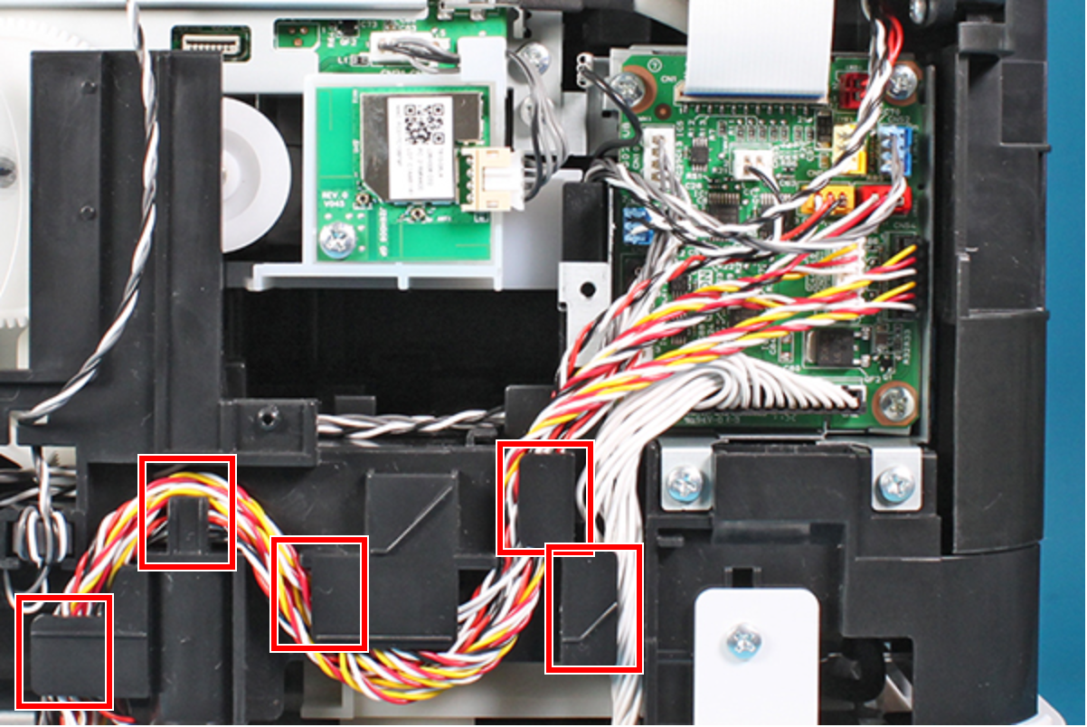 Assembly / 組み立て
Cables to be routed to A and B in the figure below are as follows.
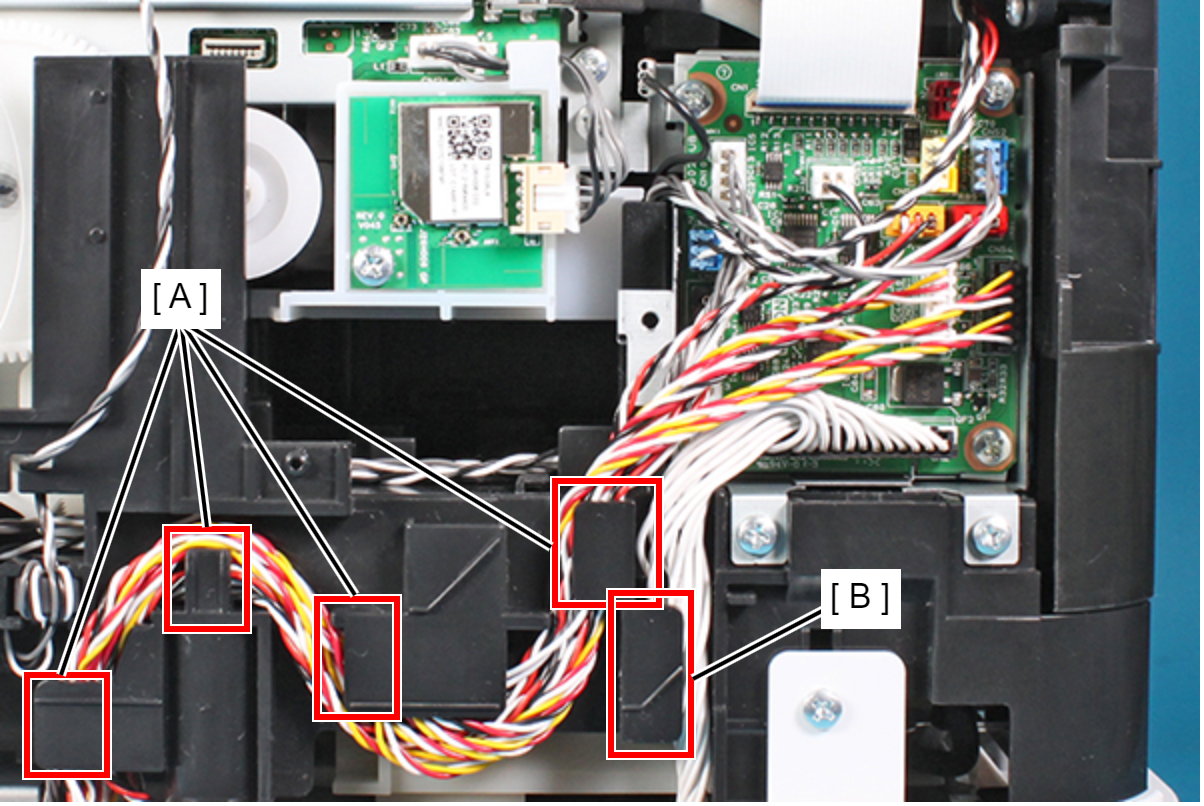
A Ink End Sensor (C/M) (CN30)
Ink End Sensor (Bk/Y) (CN31)
Ink Leak Sensor 1 (CN11)
Ink Leak Sensor 2 (CN12)
Ink Leak Sensor 3 (CN54)
Ink Leak Sensor 4 (CN55)
Temperature and Humidity Sensor(CN10)
B Drawer Connector (CN2)
Cover Open Sensor (CN22)
- Pull the Decompression Pump Cable (A) out from the hole of the Frame Base, and remove the ferrite core (B).
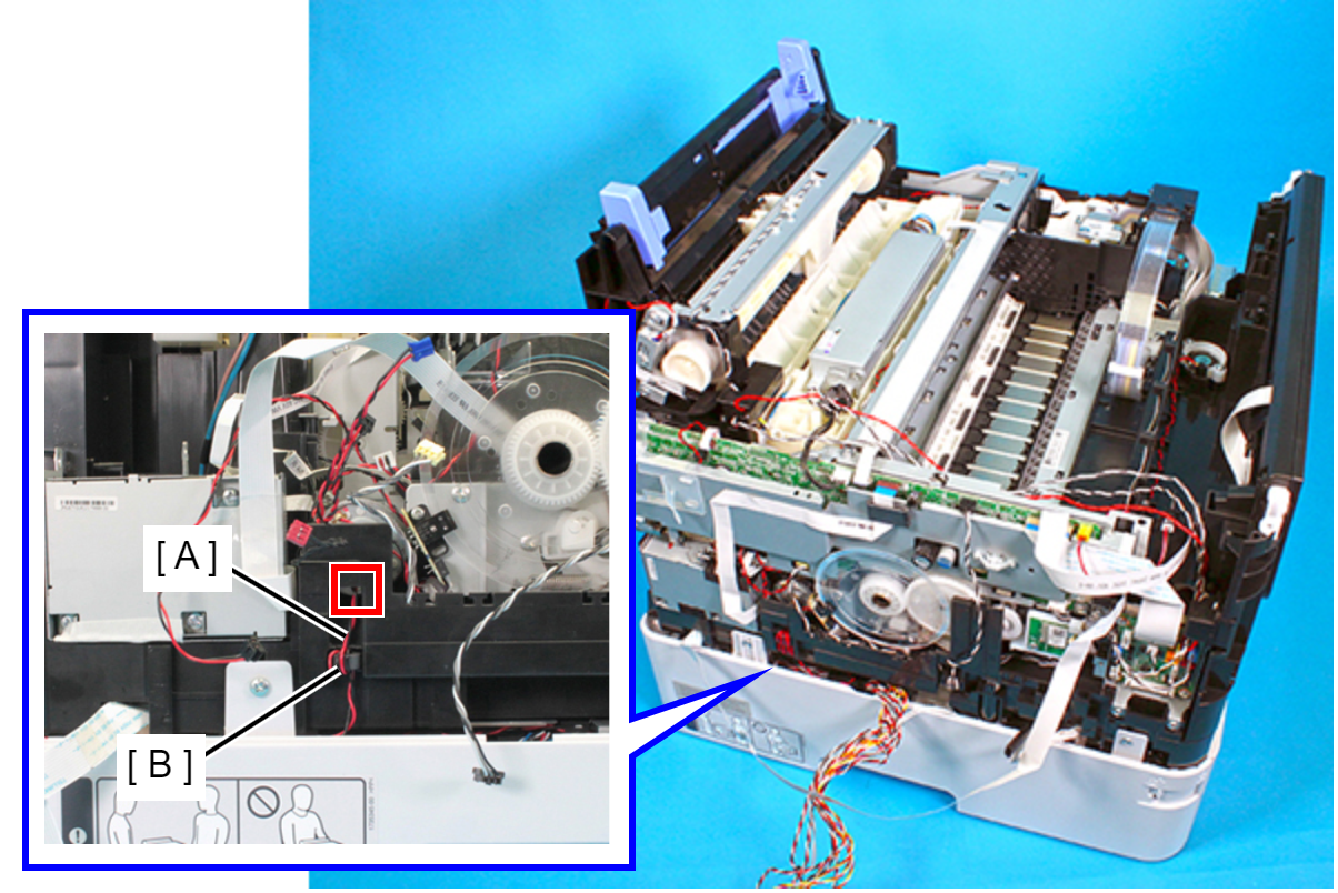
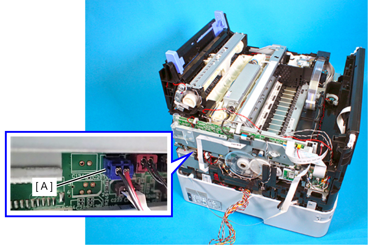
- Disconnect the Decompression pump cable (A) from the connector of the Main Board.
- Remove the three screws that secure the Ink Supply Unit (A).
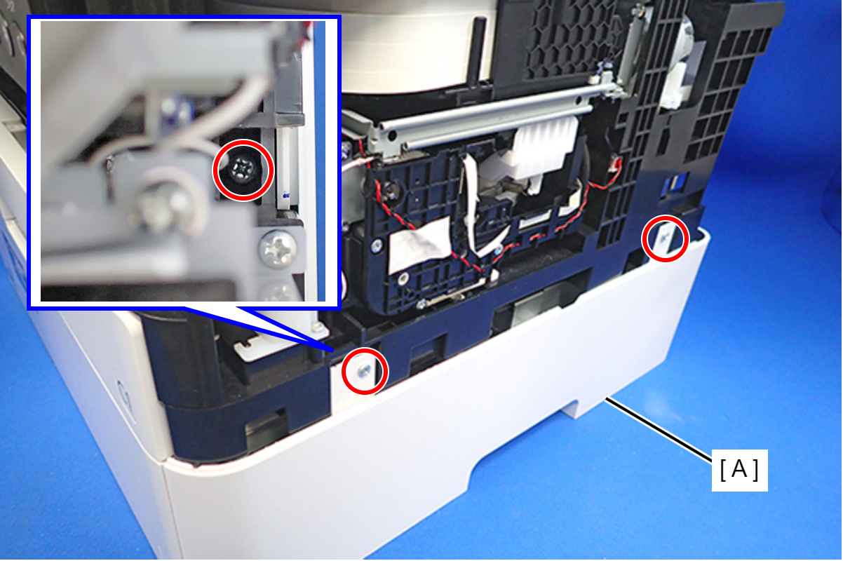
- : C.B.P-TITE-SCREW-3x10-F.ZN-3C
- Remove the two screws that secure the Ink Supply Unit (A).
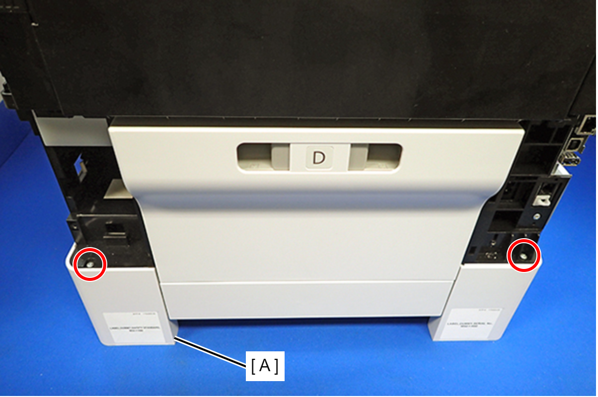
- : C.B.P-TITE-SCREW-3x10-F.ZN-3C
- Remove the three screws that secure the Ink Supply Unit (A).
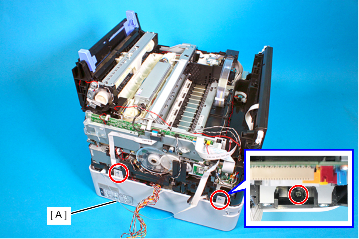
- : C.B.P-TITE-SCREW-3x10-F.ZN-3C
 Caution / 注意
As ink may adhere in the following steps, prepare a waste cloth or the like in advance.
- Remove the Ink Supply Tube Assy (B) from the Joint (A).
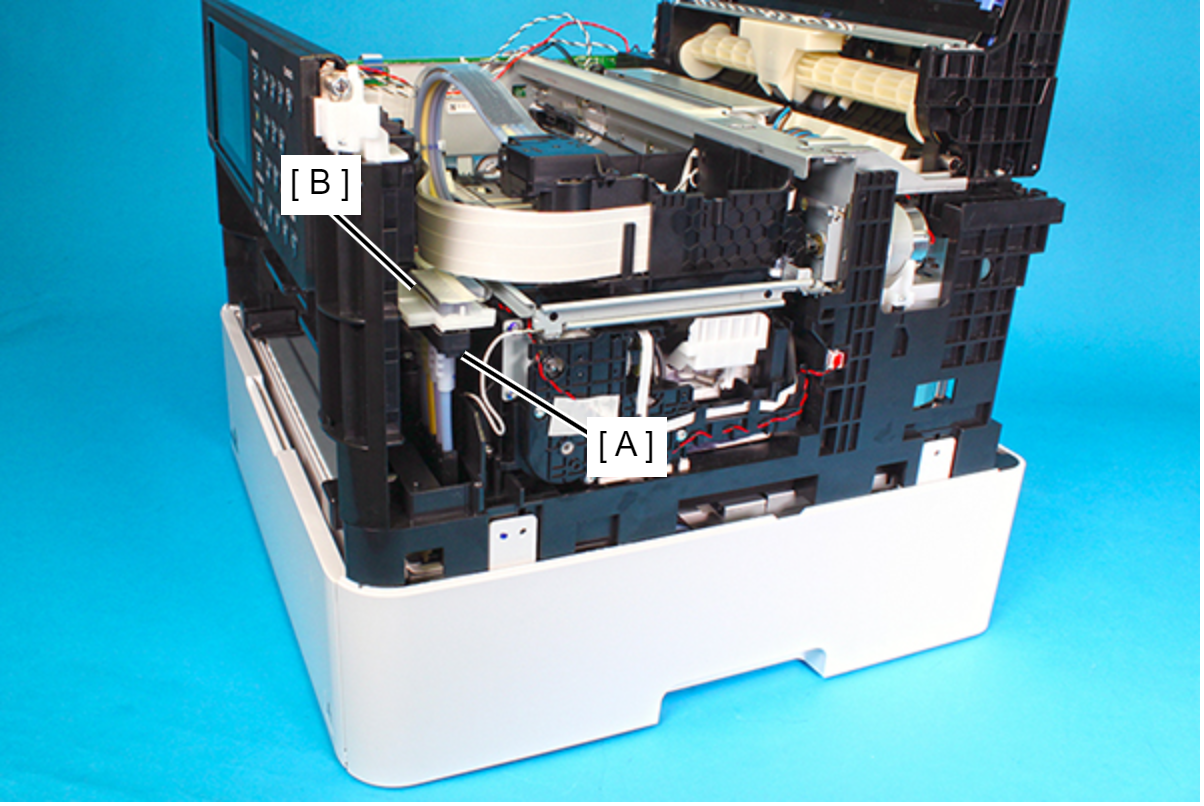 Caution / 注意
- In order to prevent injuries from the edge of the metal frame (A), use gloves when lifting the printer.
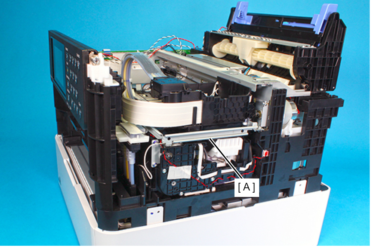
- Lift carefully so as not to touch the PF scale (A) on the left side of the main body. If you touch the PF scale, clean it with a clean cloth.
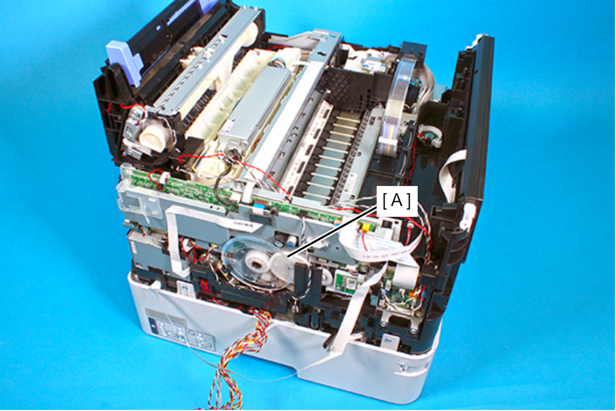
- In order to prevent injuries from the edge of the metal frame (A), use gloves when lifting the printer.
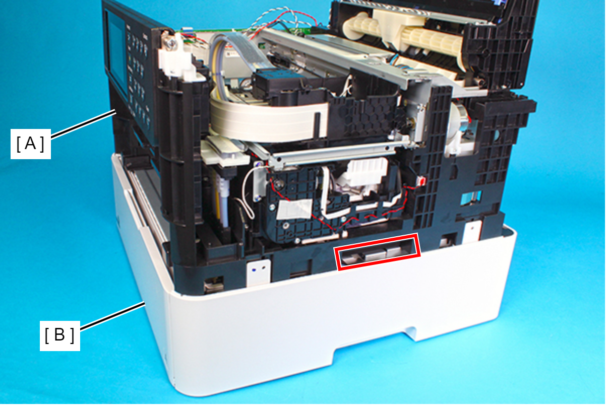
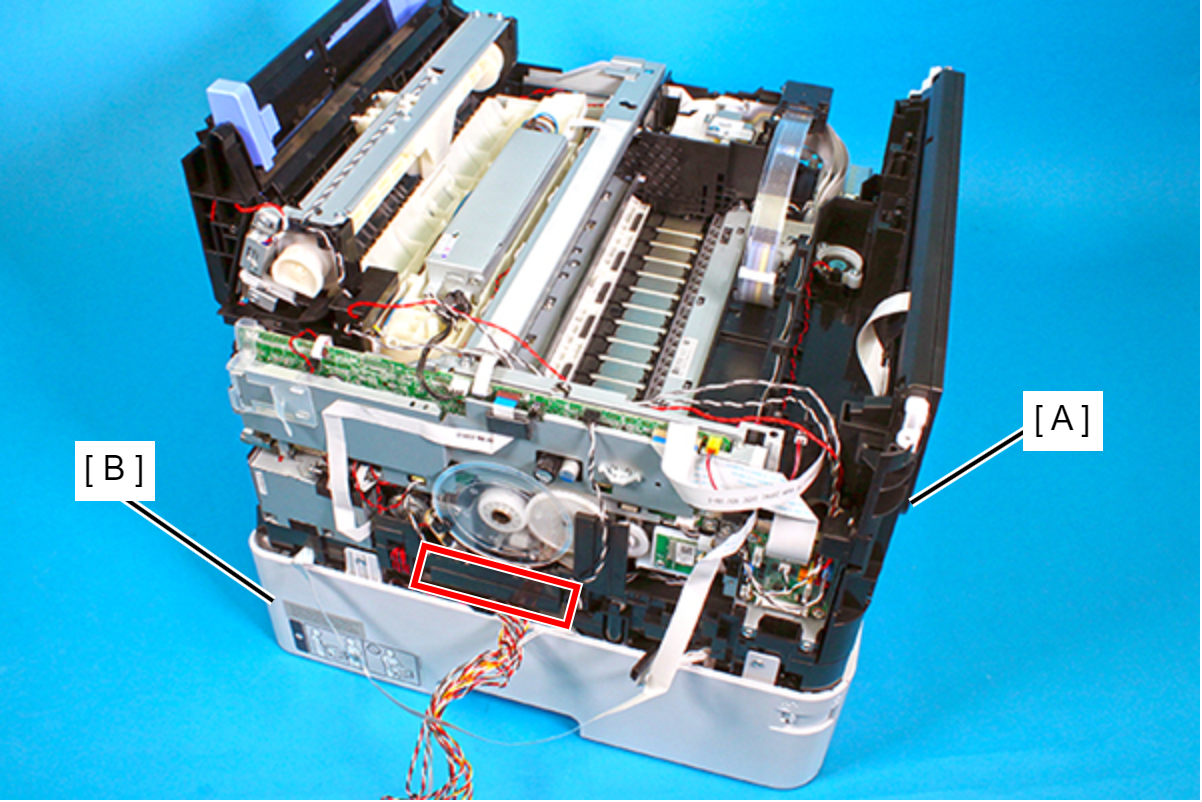
- Lift the printer (A) vertically to remove it from the Ink Supply Unit (B).
- Right side
- Left side
 Assembly / 組み立て
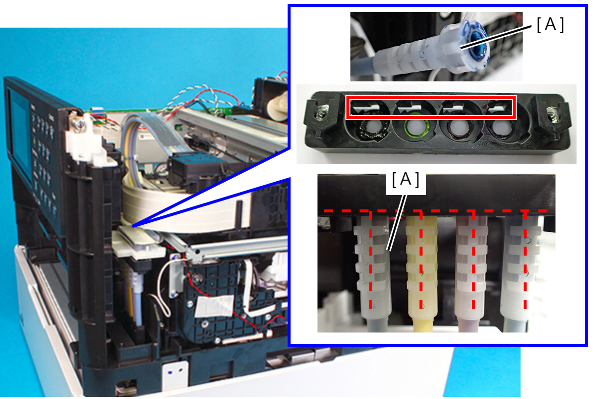
When disassembling/assembling, misalignment between tube of the Ink Supply Tube and the joint part of the tube affects ink supply.
When assembling, make sure to rotate the tube to check if it is secured with the joint part.
Make sure the rib (A) of the tube and the joint part is attached vertically as shown in the figure below.
- Right side
- Remove the three screws, then remove the Retard Roller Assy (A).
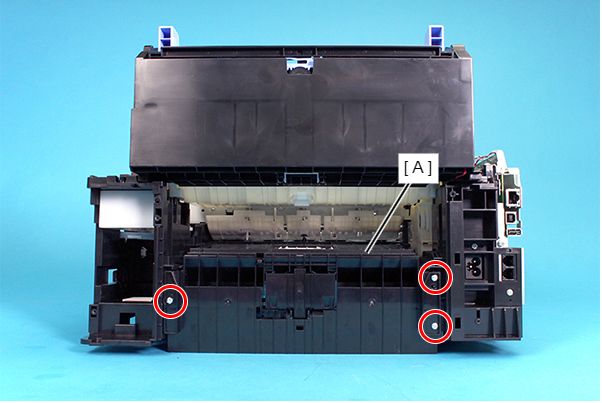
- ; C.B.P-TITE-SCREW-3x10-F/ZN-3C
Assembly / 組み立てWhen attaching the retard Roller Assy (A), make sure to align the positioning hole on the Retard Roller Assy with the dowels on the Frame Base (B).
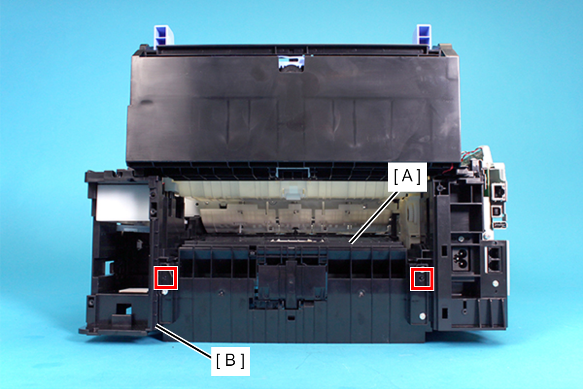
- Remove the two screws, then remove the Feed Sensor Assy.

- : C.B.P-TITE-SCREW-3x10-F/ZN-3C
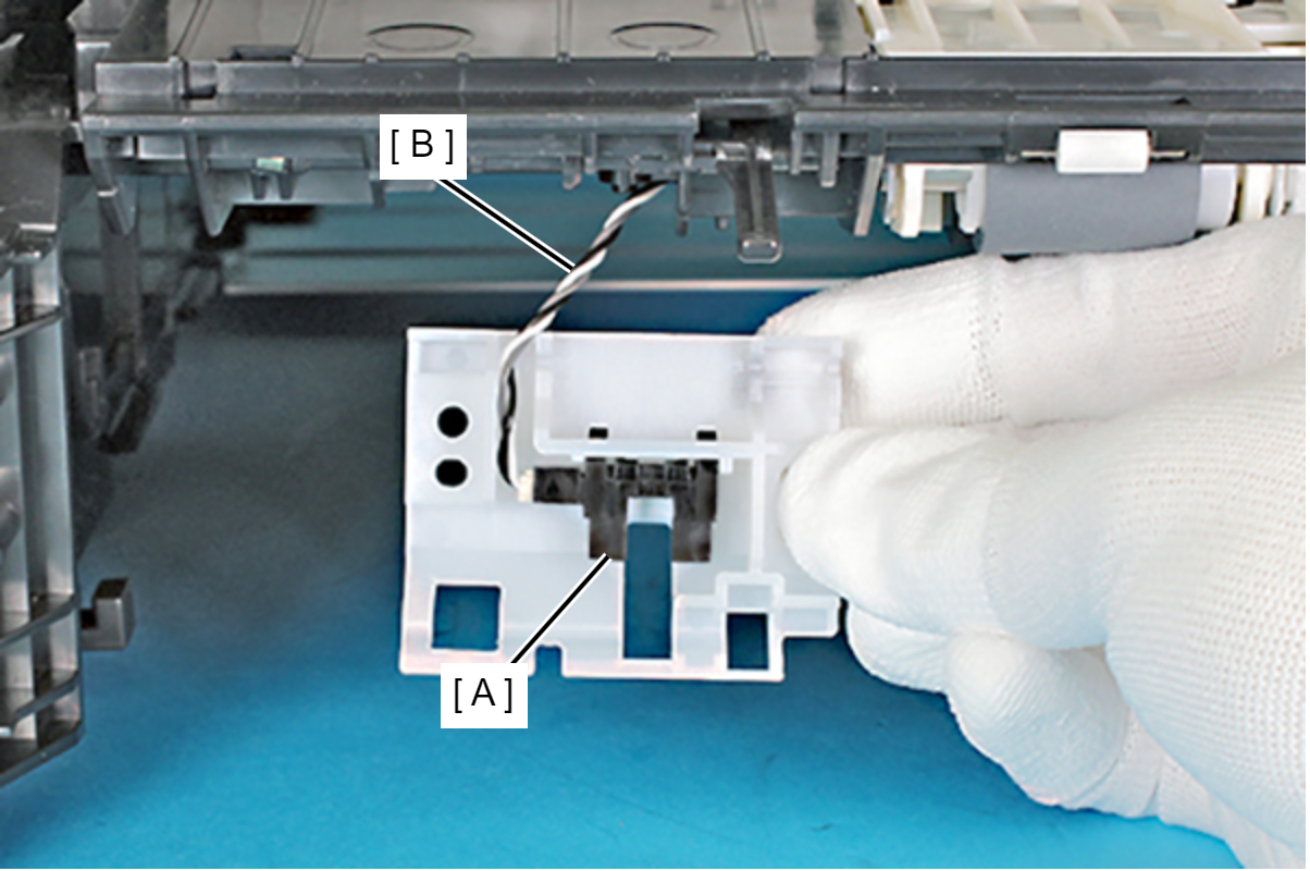
Caution / 注意In the this step, do not remove the Feed Sensor Assy too far since the Feed Sensor (A) is inside the Feed Sensor Assy, and the cable (B) is connected to the Feed Sensor.
 Assembly / 組み立て
Pull out the Feed Sensor cable (A) from the slit on the Feed Sensor Assy (B), then route the cable through the two hooks and notch shown below.
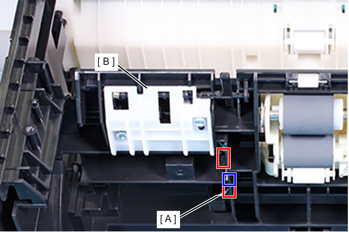
- Release the foot of the Feed Sensor Detection Lever Spring (A) from the rib (B).
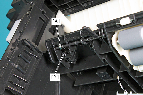
- Pull the Feed Sensor Detection Lever (A) out from the Frame Base (B) while warping the Feed Sensor Detection Lever (A).
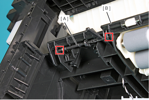
- Remove the Feed Sensor Detection Lever Spring (B) from the Feed Sensor Detection Lever (A).