Main Board Assy (WF-C529R Series)
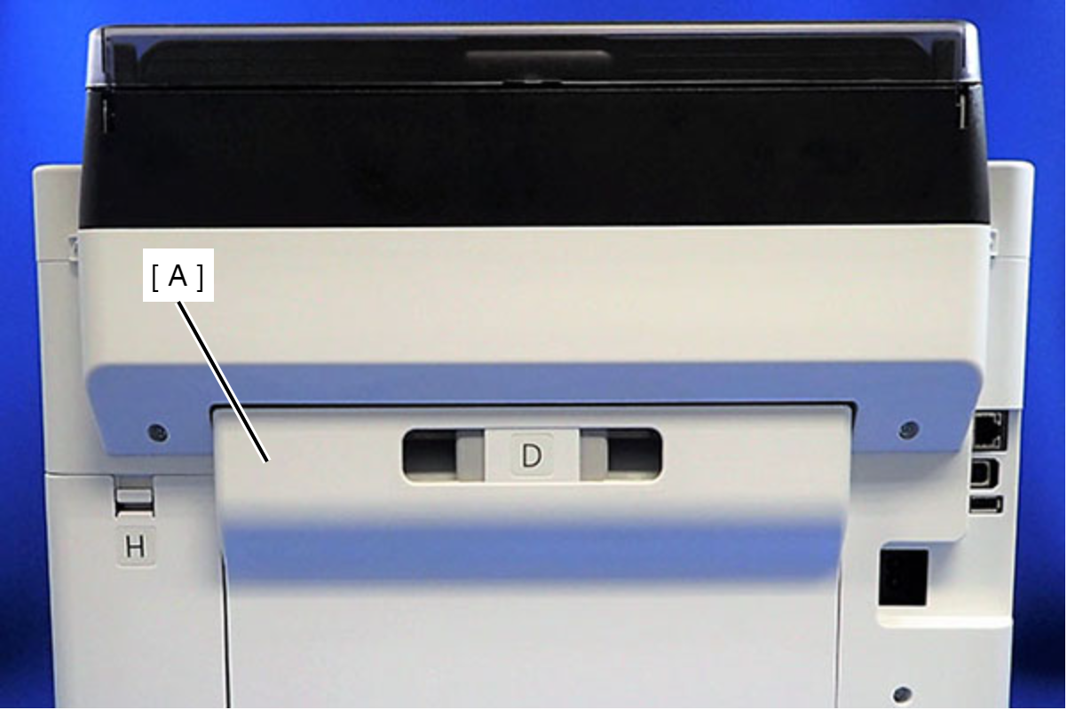
- Remove the Rear Unit (A).
- Remove the two screws that secure the ASF Cover Assy (A).
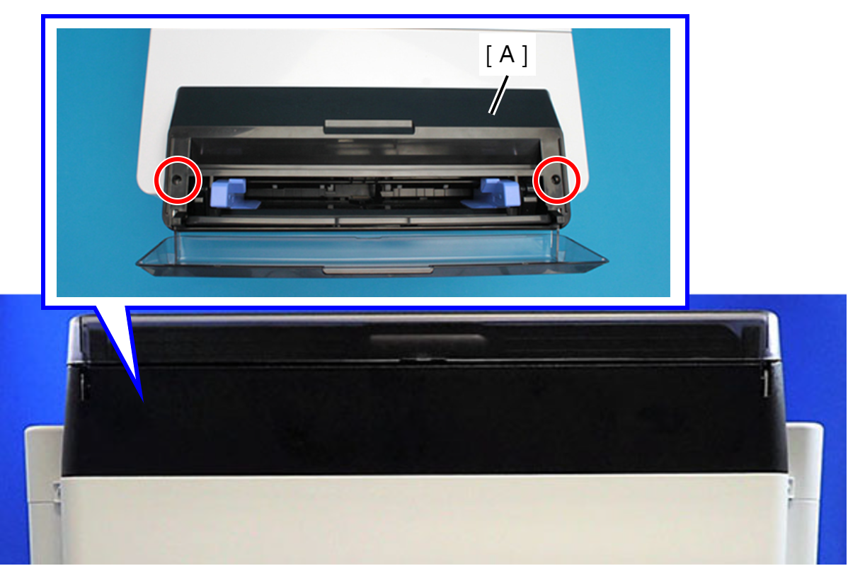
 : C.B.P-TITE-SCREW-3x10-F.ZN-3C
- Remove the four screws that secure the Rear Back Cover (A).
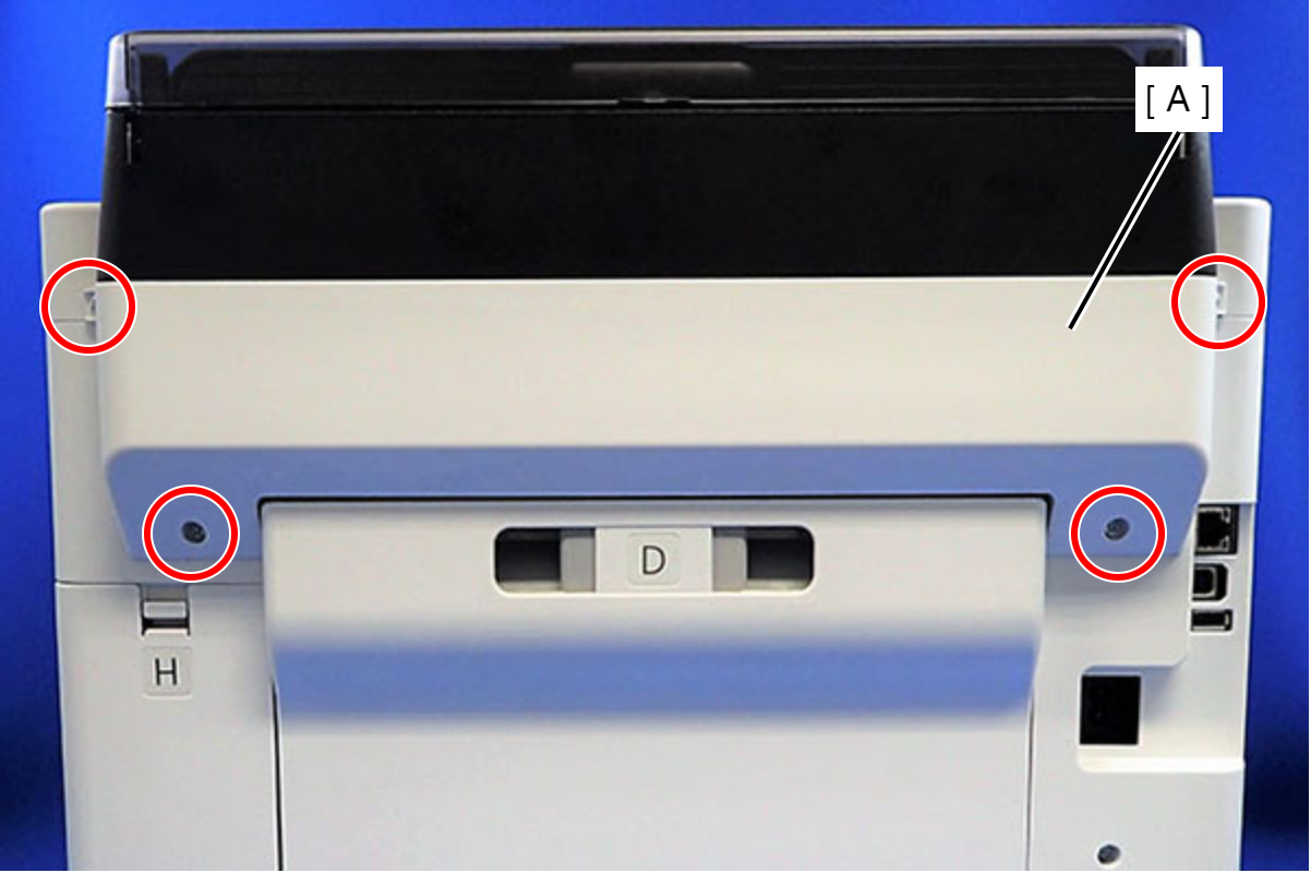
 : C.B.P-TITE-SCREW-3x10-F.ZN-3C
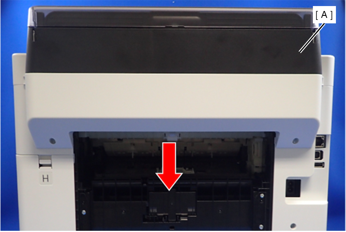
- Remove the Rear Back Cover (A) downward.
 Assembly / 組み立て
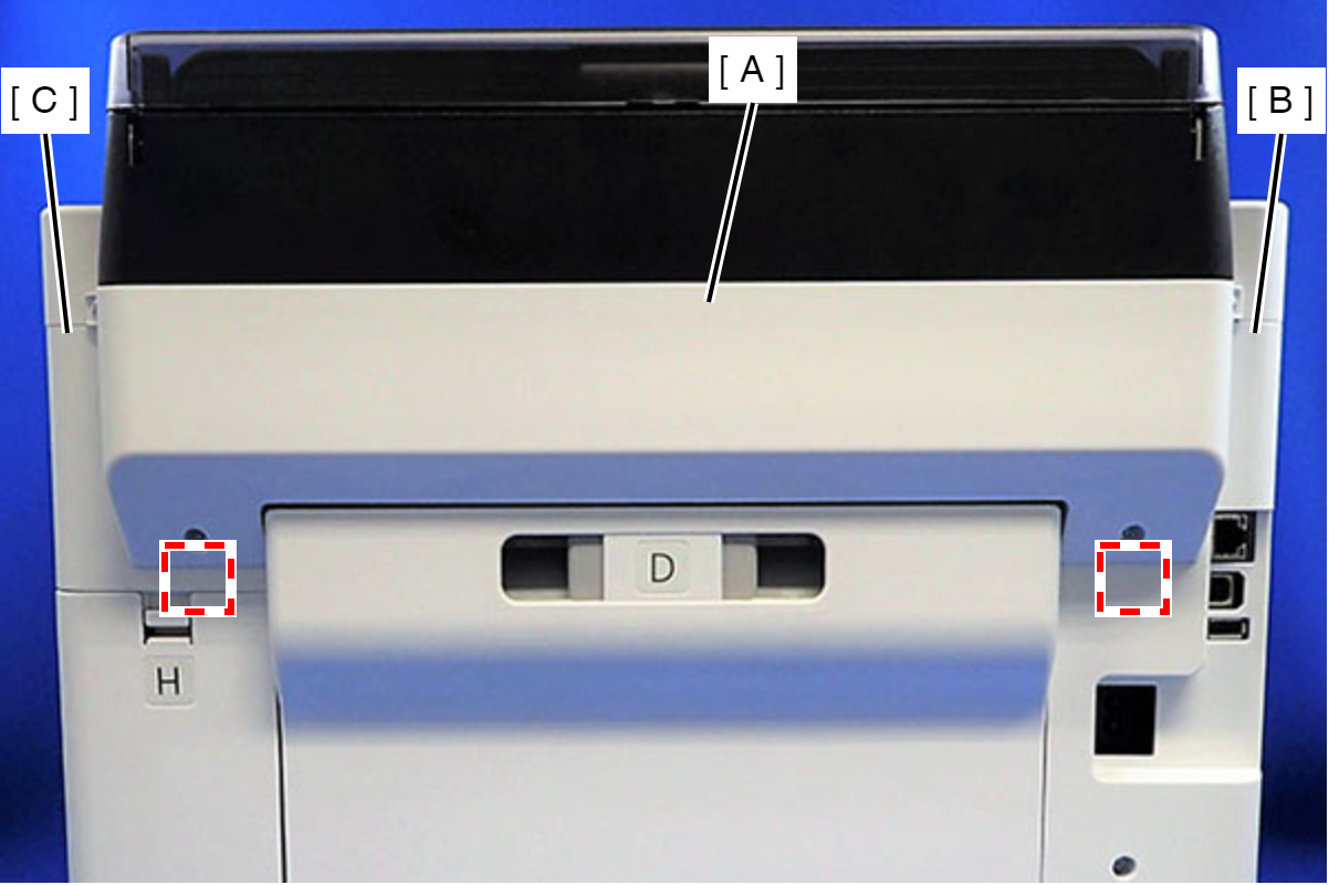
Attach the two dowels of the Rear Back Cover (A) to the positioning holes on the Housing Left (B) and the Housing Right (C).
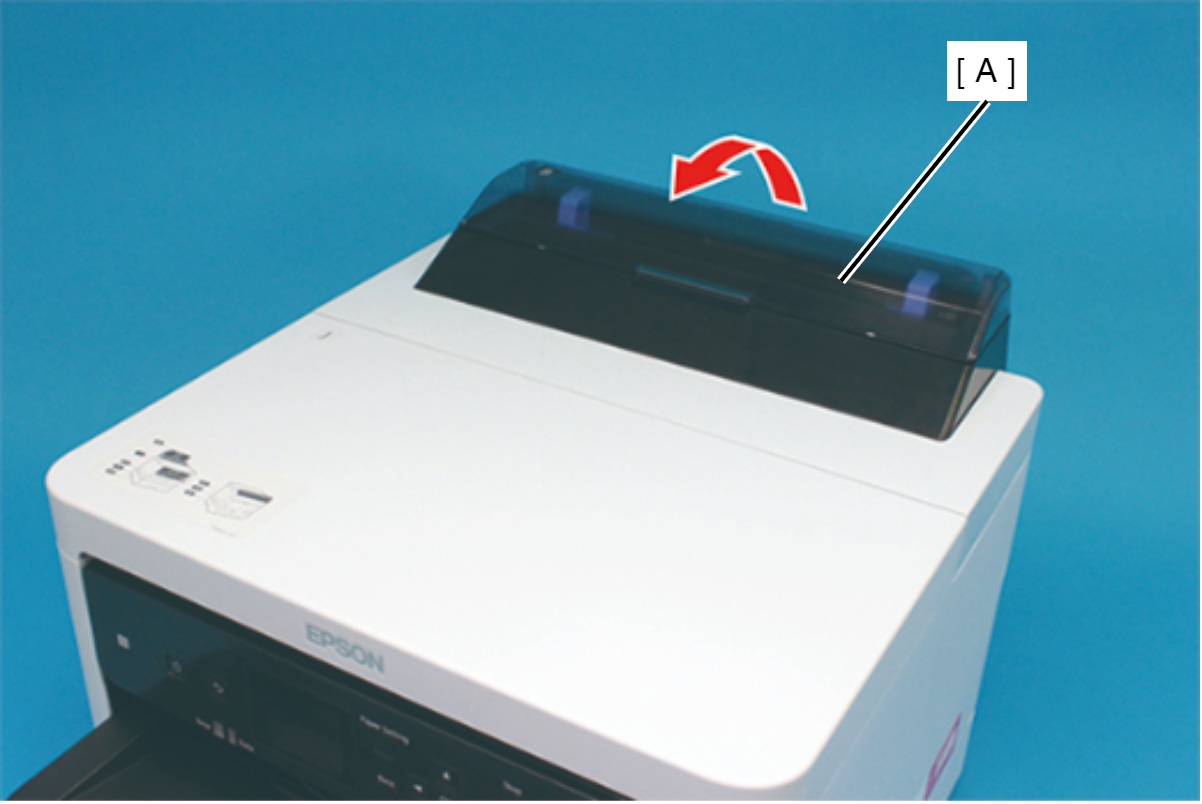
- Remove the ASF Cover Assy (A) in the direction of the arrow.
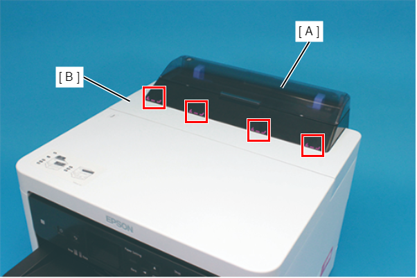
Assembly / 組み立てInsert the four tabs of the ASF Cover Assy (A) to the positioning holes of the Front Cover Retainer Plate.
- Remove the two screws securing the Front Cover Retainer Plate (A).
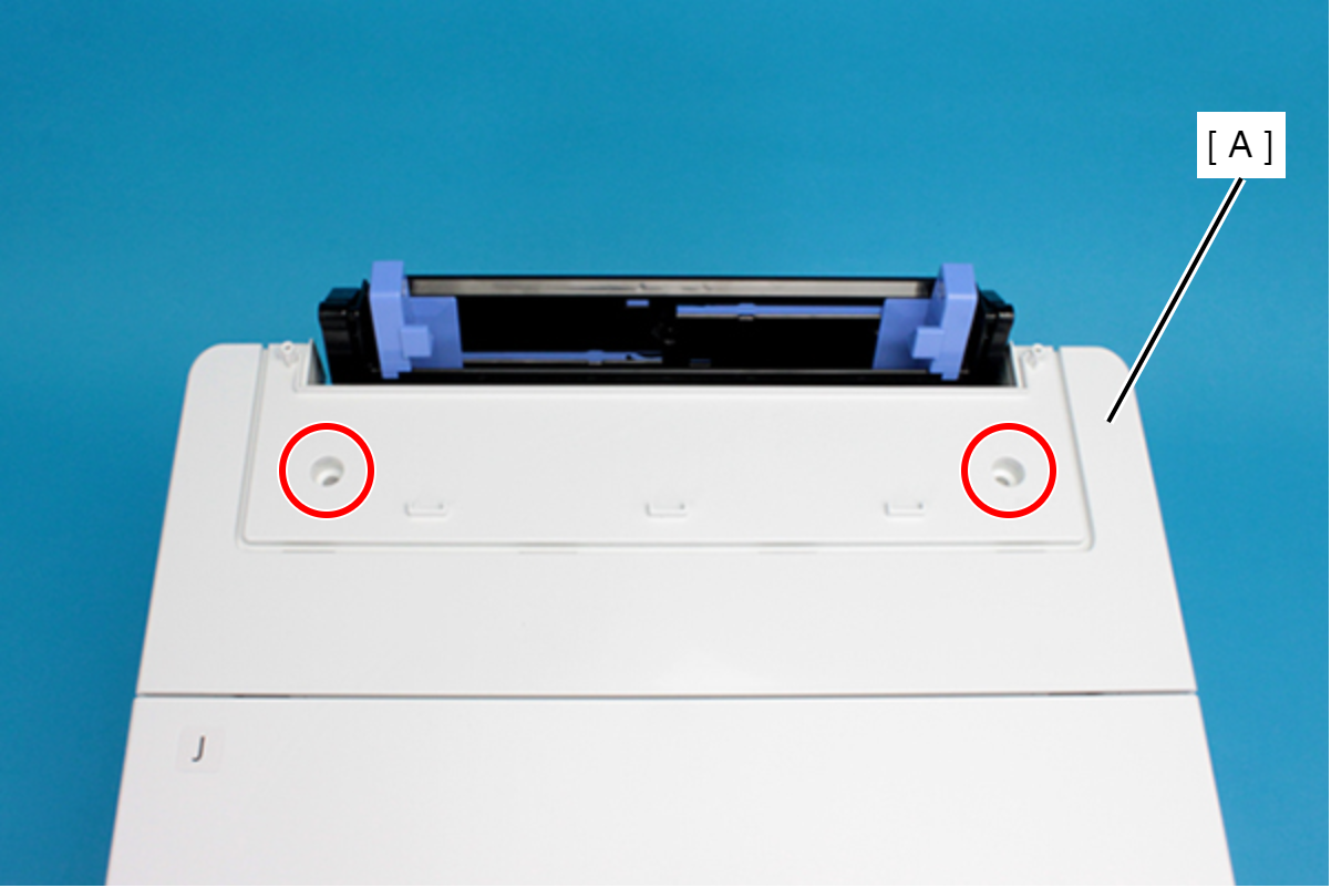
- : C.B.P-TITE-SCREW-3x10-F/ZN-3C
- Open the Printer Cover (A) and remove the four screws, and then remove the Front Cover Retainer Plate (B).
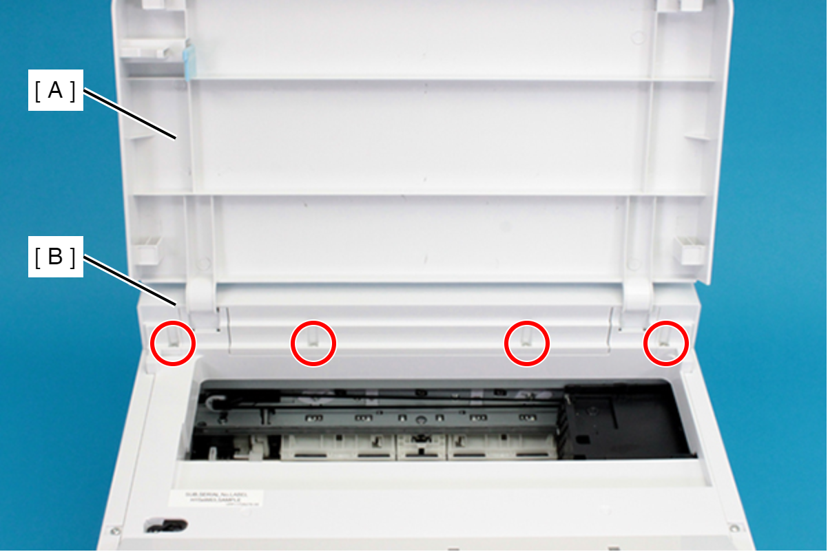
- : C.B.P-TITE-SCREW-3x10-F/ZN-3C
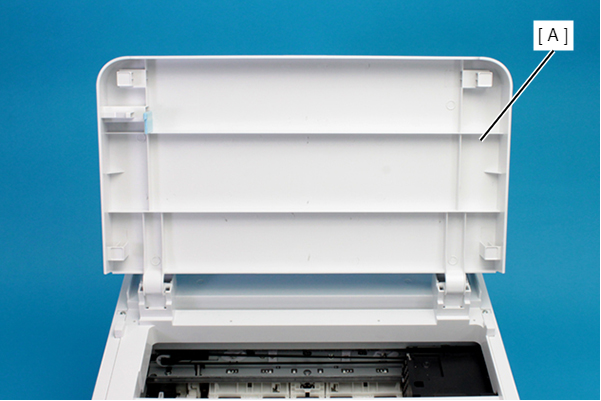
- Remove the Front Cover (A) upward.
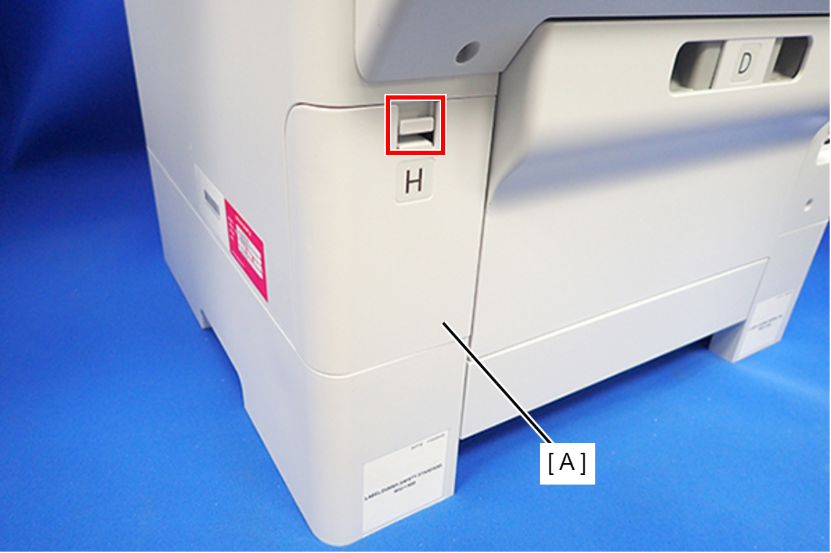
- Disengage the hook, and remove the Maintenance Box Cover (A).
- Remove the three screws that secure the Housing Right (A).
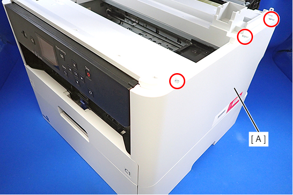
- : C.B.P-TITE-SCREW-3x10-F.ZN-3C
- Remove the two screws that secure the Housing Right (A).
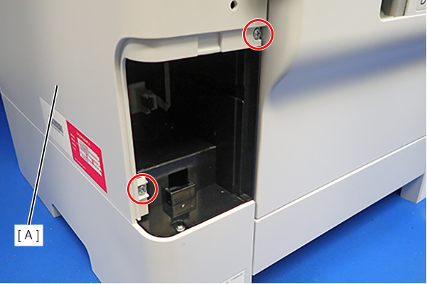
- : C.B.P-TITE-SCREW-3x10-F.ZN-3C
- Lift the Housing Right (A) to release the two hooks on the front side of the Housing Right (A), then remove the Housing Right (A).
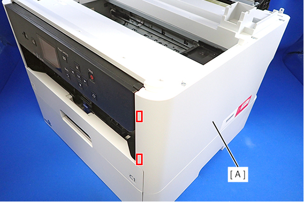 Assembly / 組み立て
Insert the four tabs of the Housing Right (A) to the positioning holes on the Ink Supply Unit (B).
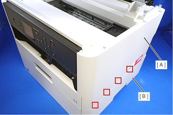
- Remove the three screws that secure the Housing Left (A).
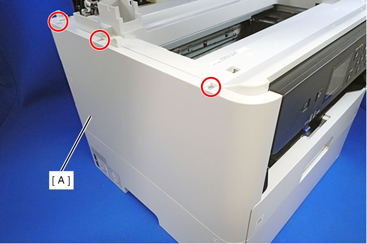
- : C.B.P-TITE-SCREW-3x10-F.ZN-3C
- Remove the two screws that secure the Housing Left (A).
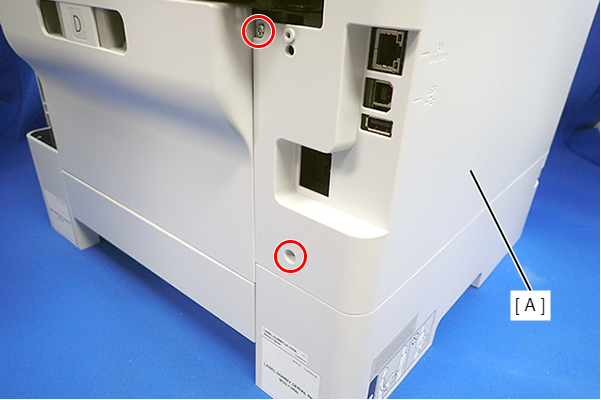
- : C.B.P-TITE-SCREW-3x10-F.ZN-3C
- Lift the Housing Left (A) to release the two hooks each on the front side and rear side of the Housing Left (A), and then remove the Housing Left (A).
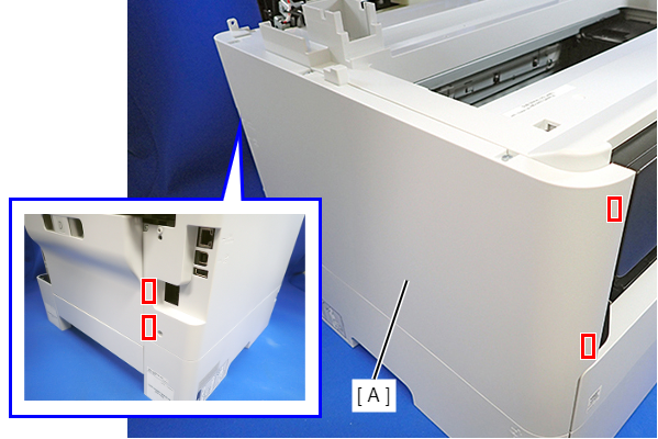 Assembly / 組み立て
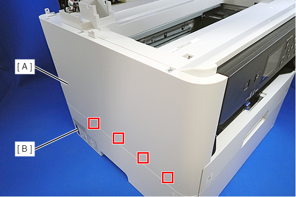
Insert the four tabs on the Housing Left (A) to the positioning holes of the Ink Supply Unit (B).
- Remove the six screws, then remove the Housing Upper (A).
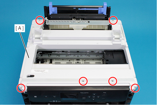
- : C.B.P-TITE-SCREW-3x10-F.ZN-3C
- Release the all cable from the Cable Guide (A).
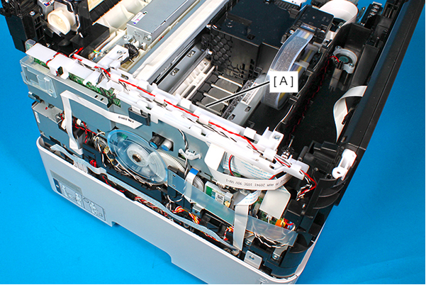
- Remove the two screws, and remove the Cable Guide (A).
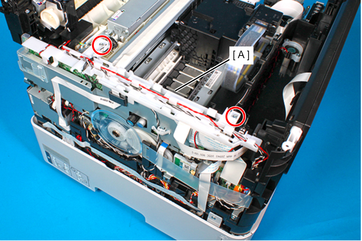
- : C.B.P-TITE-SCREW-3x10-F.ZN-3C
Assembly / 組み立て- Route the PS cable (A) through the two guides and hook on the Cable Guide.
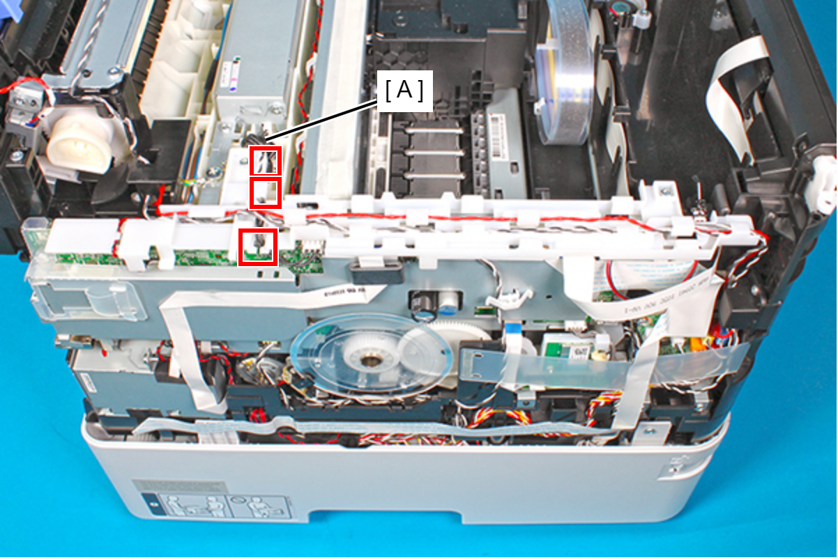
- Route the Rear ASF Solenoid cable (A) through the six hooks on the Cable Guide.
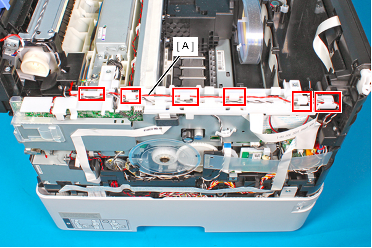
- Route the Rear Unit Detection Sensor cable and Rear ASF Paper Detection Sensor cable (A) through the three hooks and the three hooks on the Cable Guide.
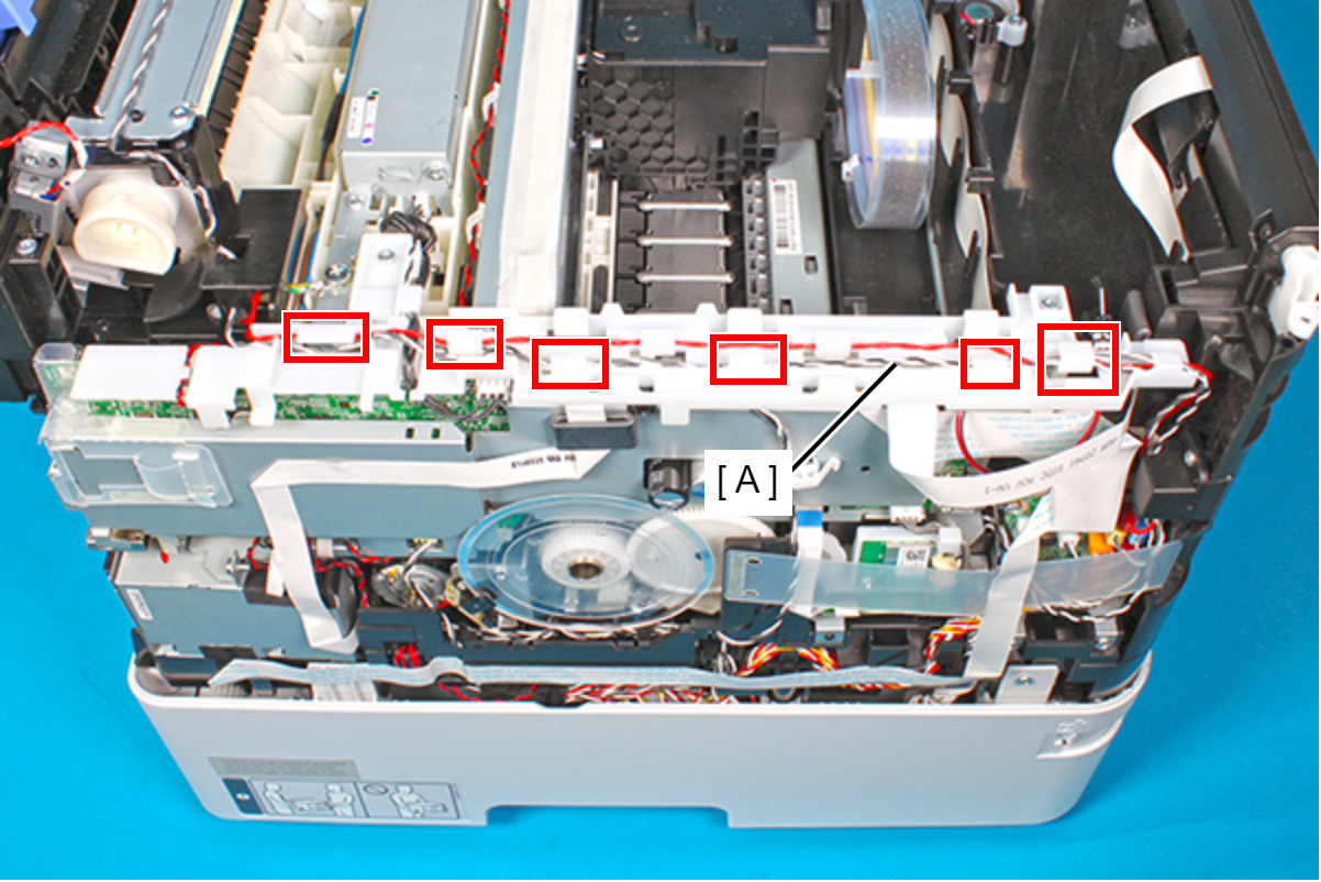
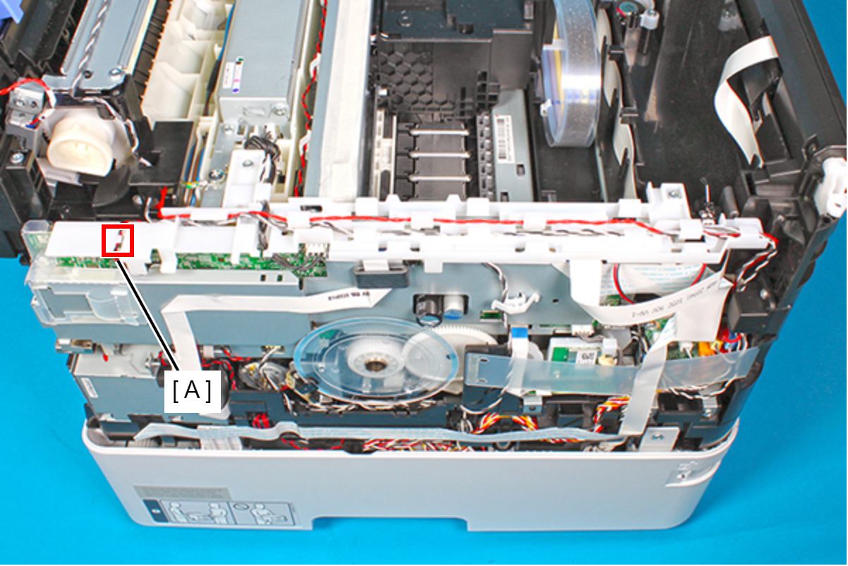
- Route the ASF motor cable (A) through the guide on the Cable Guide.
- Remove the two screws, then remove the PS Ground Plate (A).
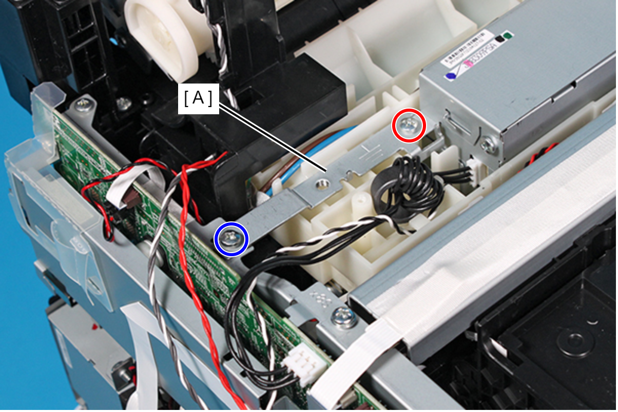
- : C.B.P-TITE-SCREW-3x10-F.ZN-3C
 : C.B.S-TITE-SCREW-3x6-F.ZN-3C
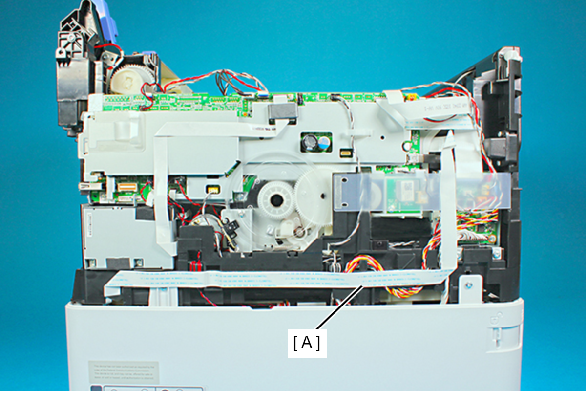
- Peel off the CRCM FFC (A).
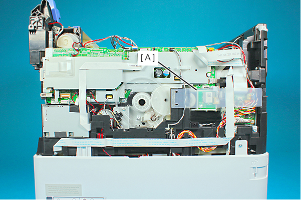
- Peel off the CRCR FFC Sheet (A).
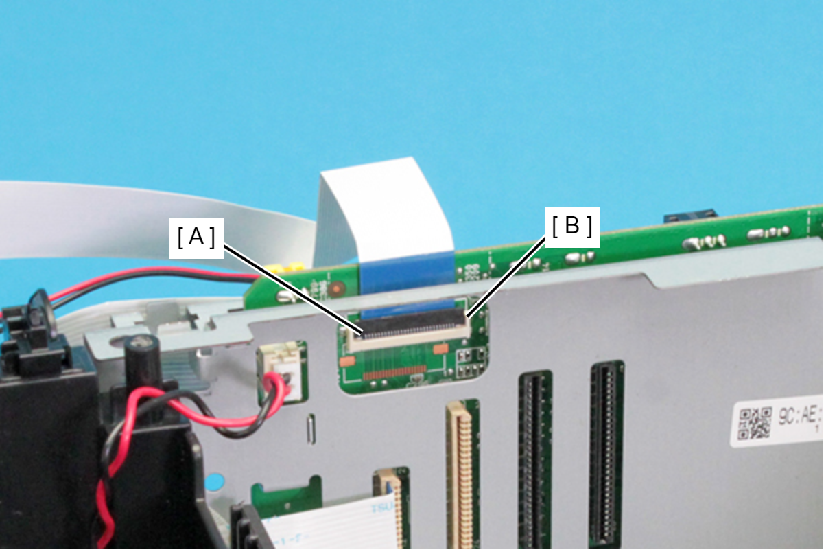
 Check Point / チェックポイント
When disconnecting the Panel FFC (CN42) (A), make sure to unlock the connector lock (B) beforehand.
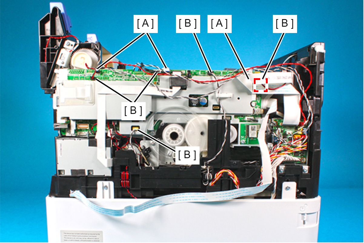
Disconnect the FFC (A) and cables (B) from the connectors (CN2, CN9, CN58, CN74, CN80, CN44, CN110, CN55, CN609) on the Main Board Assy.
- Disconnect the FFC (A) and cables (B) from the connectors (CN67, CN66, CN68, CN42, CN8) on the Main Board.
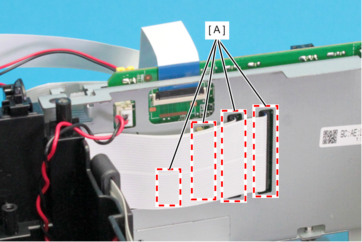
- Disconnect the cable (A) from the connector (CN31) on the Main Board.
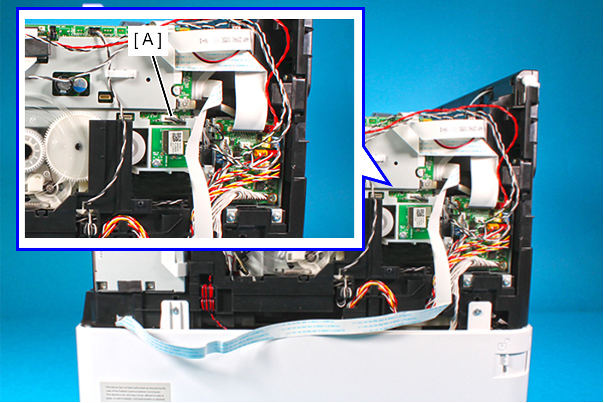
- Disconnect the FFC (A) and cables (B) from the connectors (CN50, CN52, CN72, CN73, CN75, CN77) on the Main Board.
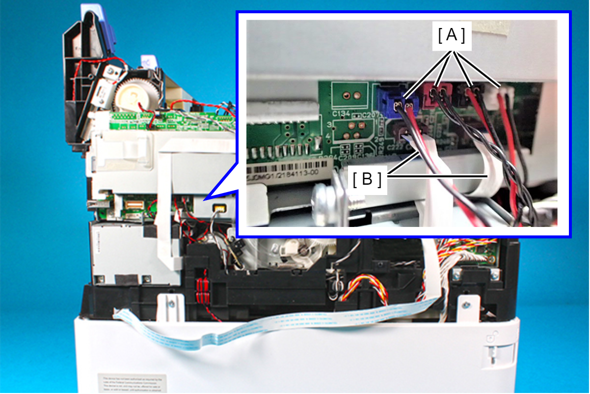
- Peel off the Fax FFC (A) from the Shield Plate, and Pull the Fax FFC out from the ferrite core (B).(WF-C579R only)
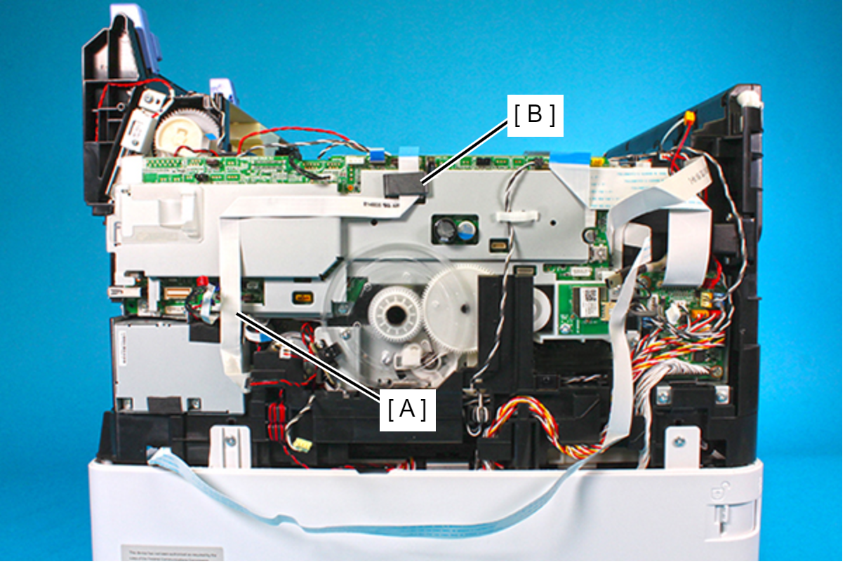
- Release the PE sensor cable (A) from the clamp.
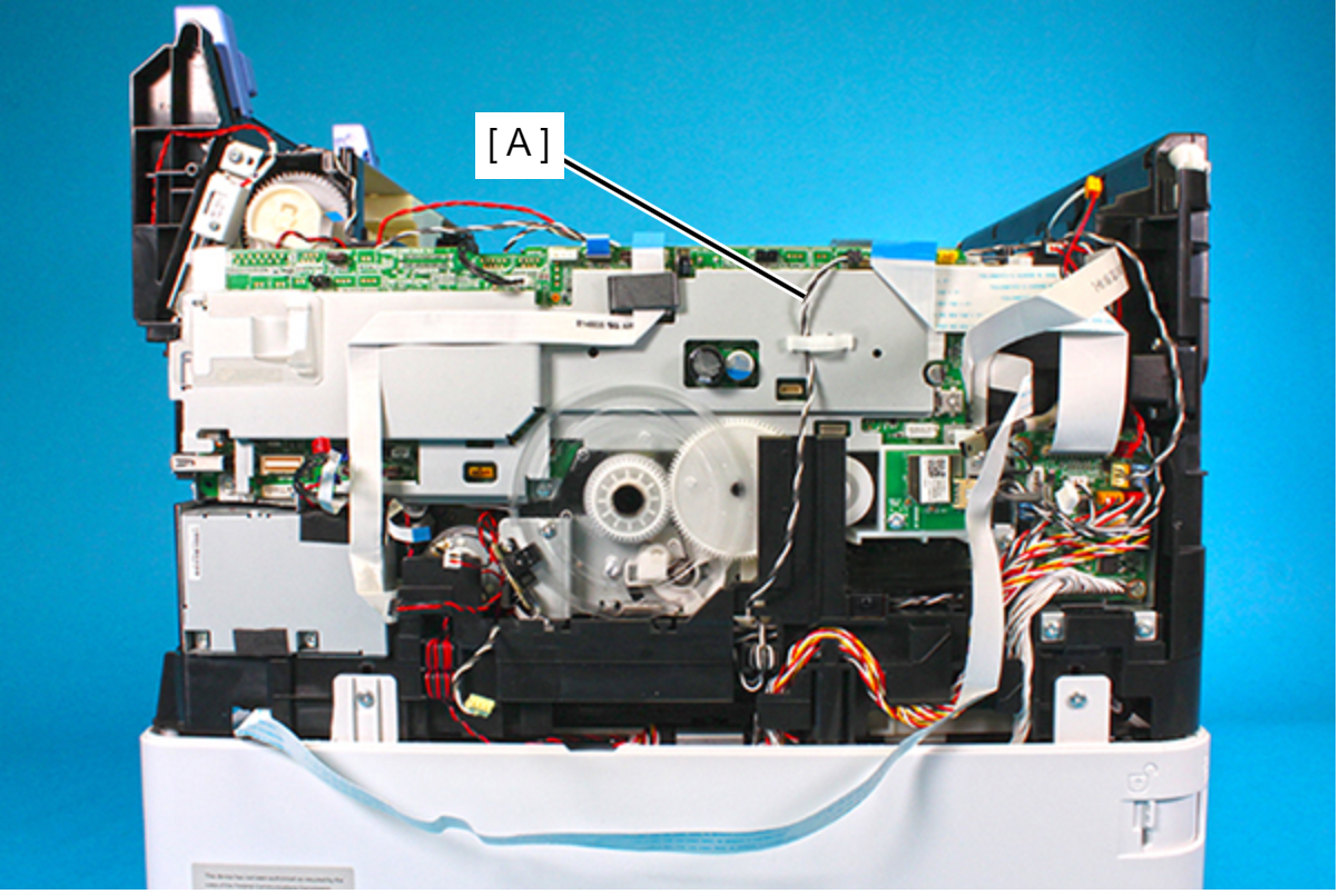
- Peel off the Relay FFC (A) from the Shield Plate.
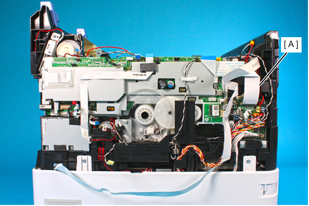
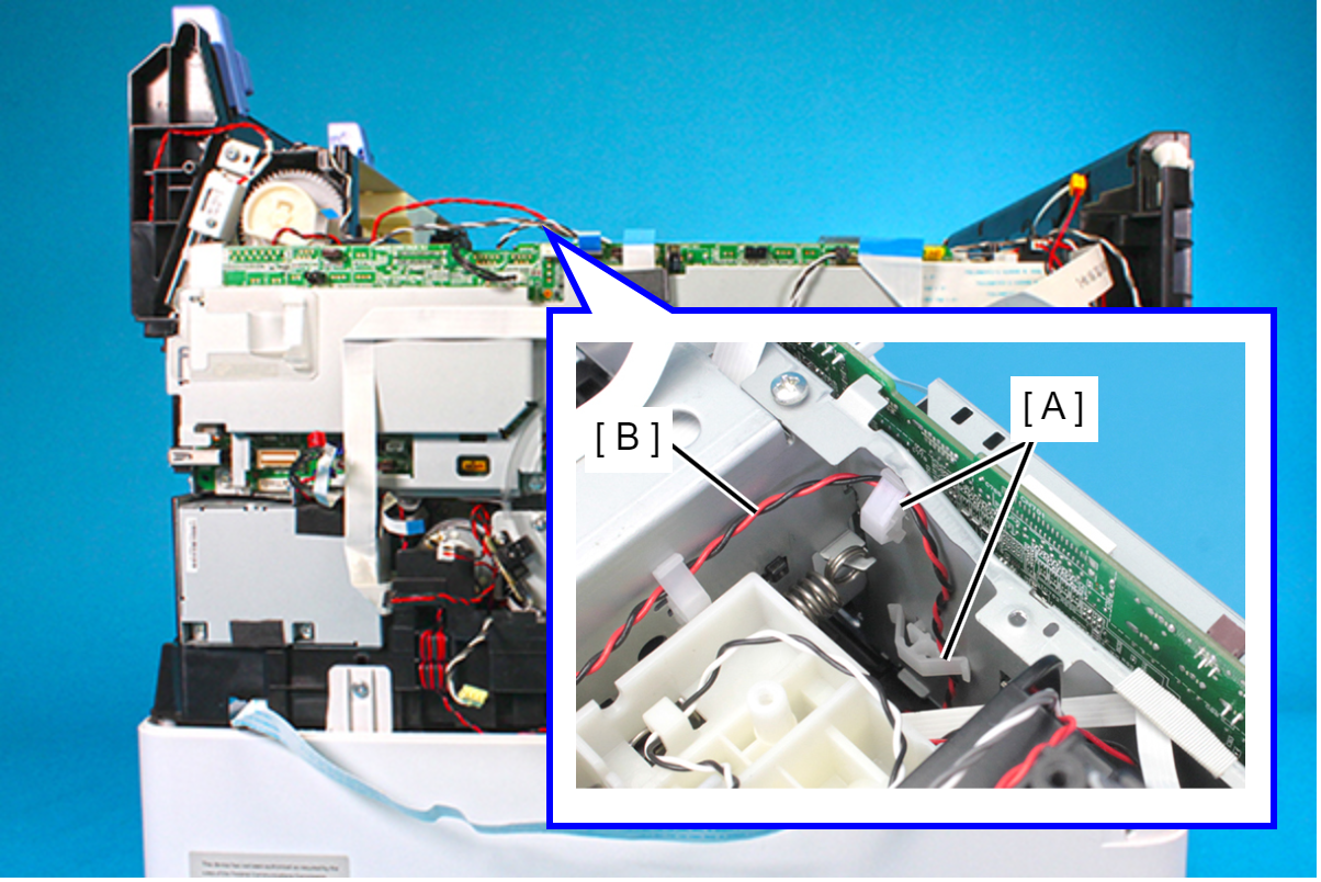
- Release the CR motor cable (B) from two clamps (A).
- Remove the following screws that secure the Main Board Assy.
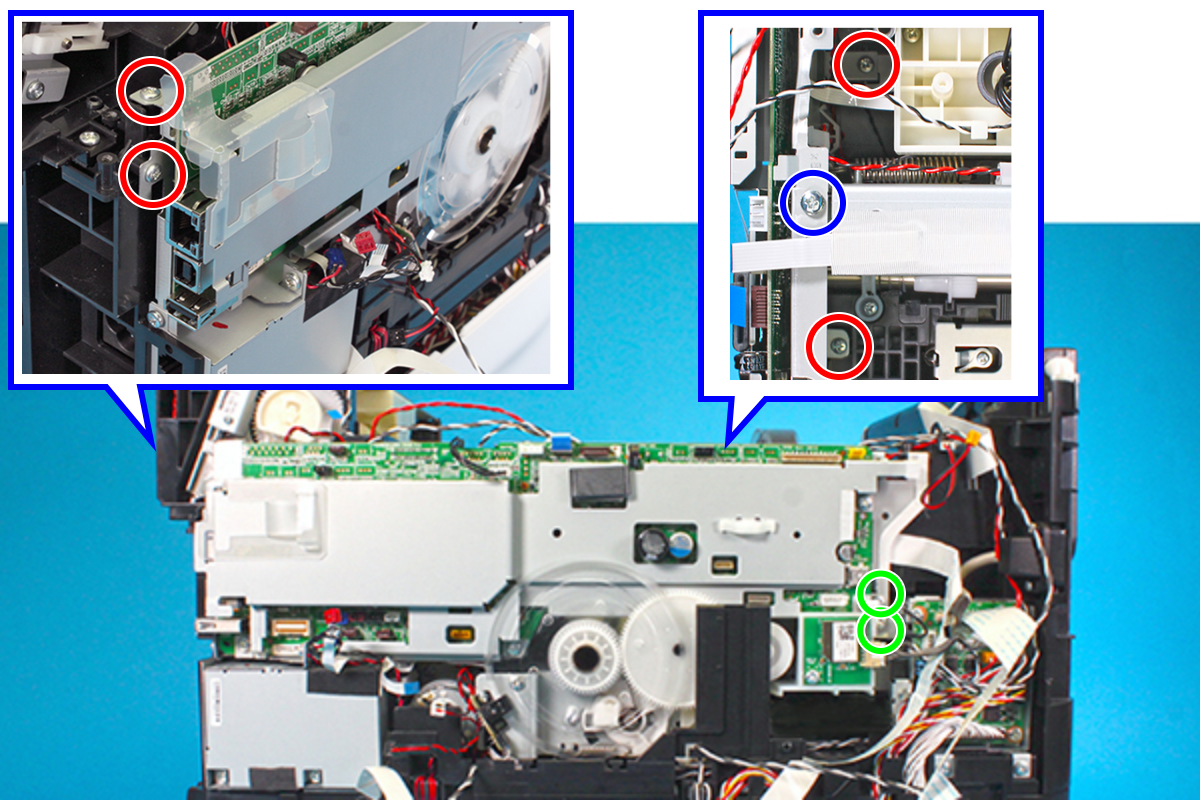
- : C.B.P-TITE-SCREW-3x10-F.ZN-3C
 : C.B.S-TITE.P4.SCREW-3X8-F.ZN-3
 : C.B.S-TITE-SCREW-3x6-F.ZN-3C
 Caution / 注意
In the next step, be careful not to damage the PF Scale (A).
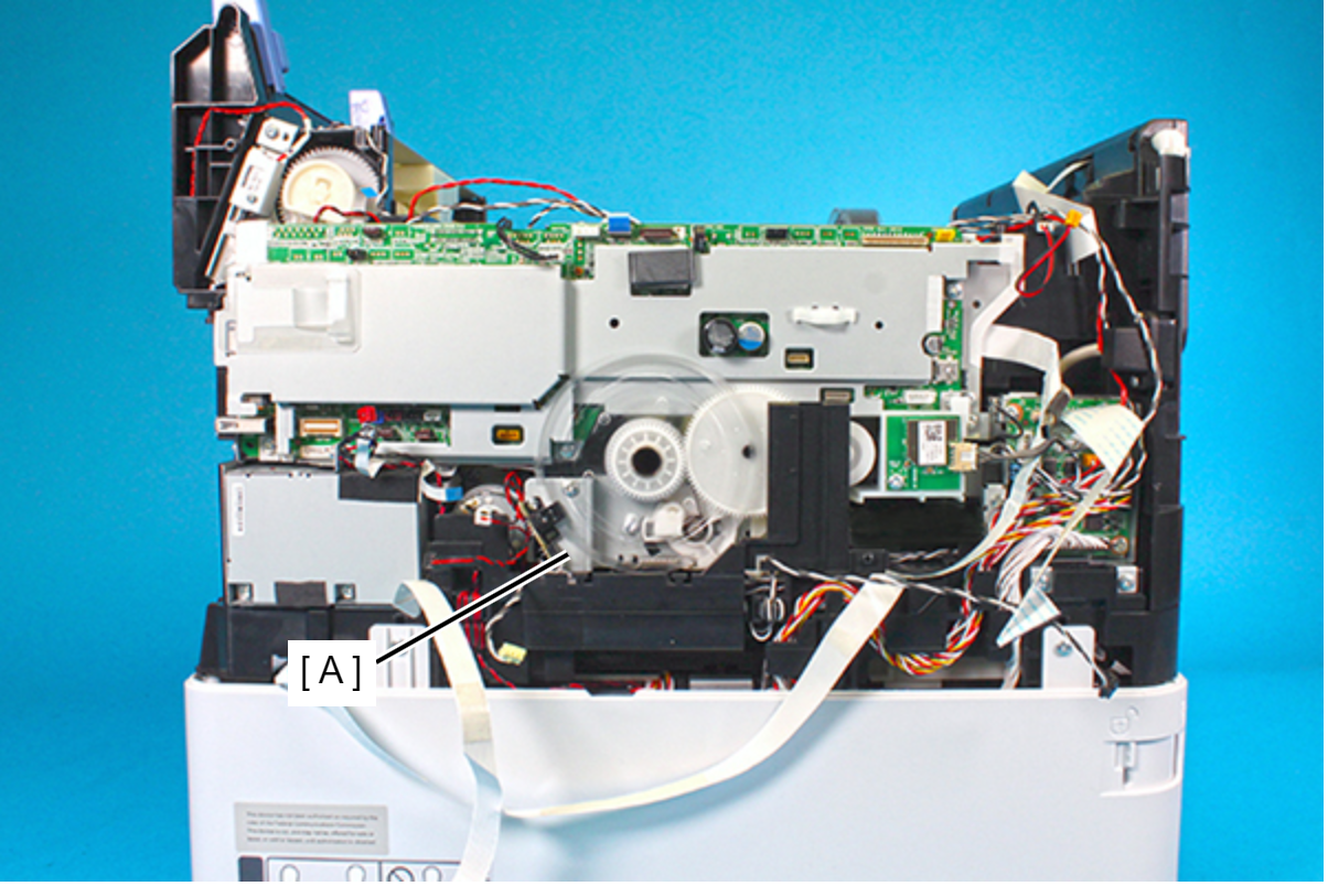
- Disengage hook of the Main Board Assy from the hole of the CR Guide Frame, then remove the Main Board Assy upward.
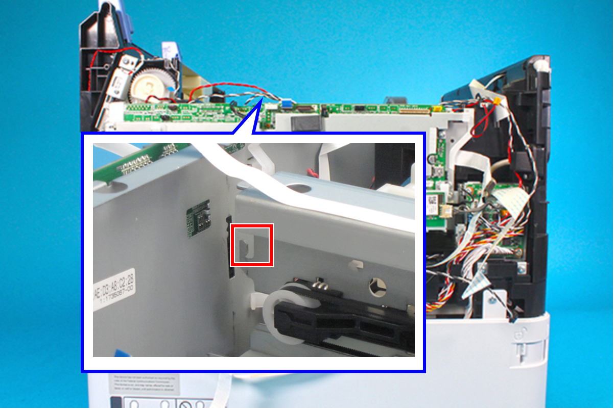 Assembly / 組み立て
Secure the PF Encoder FFC (A) with double-sided tape (B) as shown below.