
B43 HEAD ANGULAR ADJ. MECH
Overview
Use software to correct the vertical/horizontal tilt shift that may occur when installing the printhead.
Paper and feed tray
Document size: A4
Paper type: Photo matte paper
Paper feed tray: Rear ASF Unit
Adjustment pattern
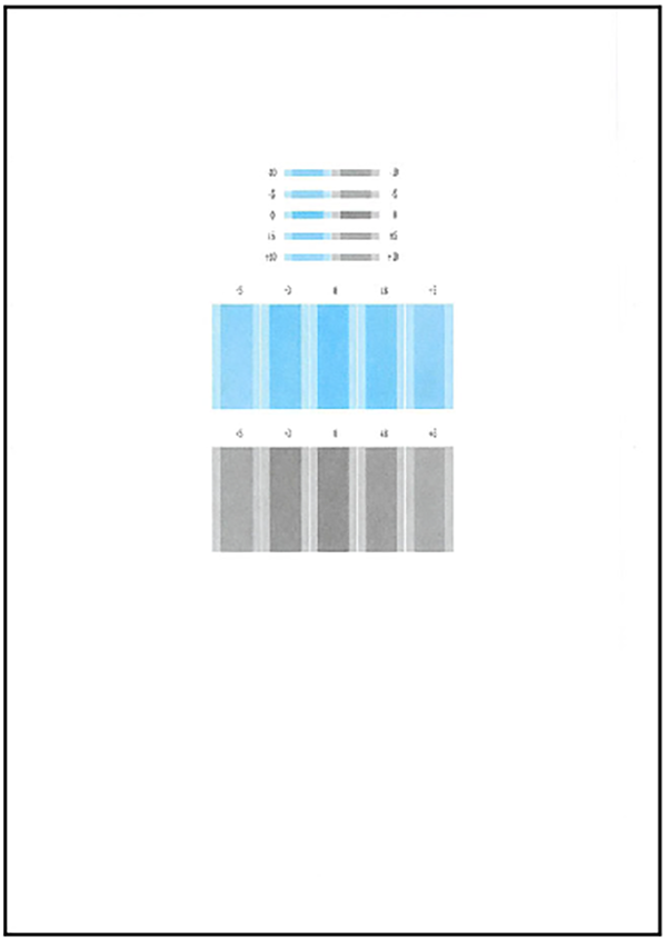
Judgment method
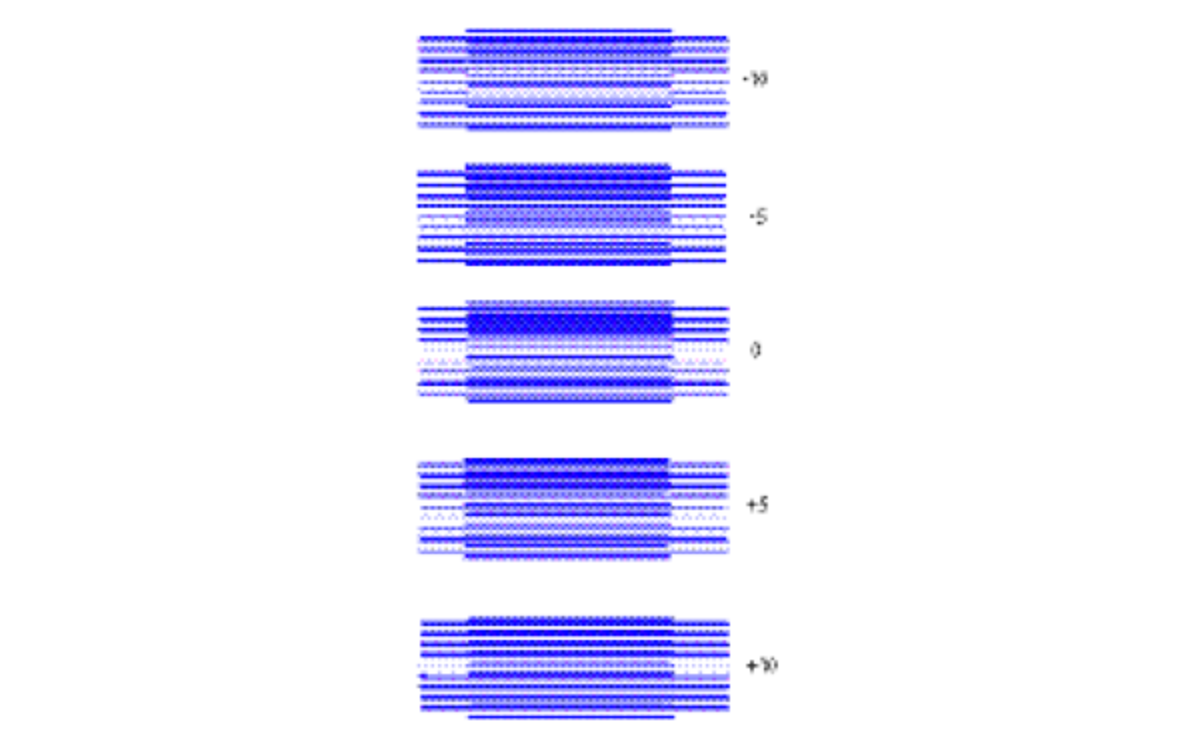
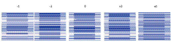
The interval of the pattern lines will be adjusted so that it is most equal when the adjustment value is “0.”
Preparation
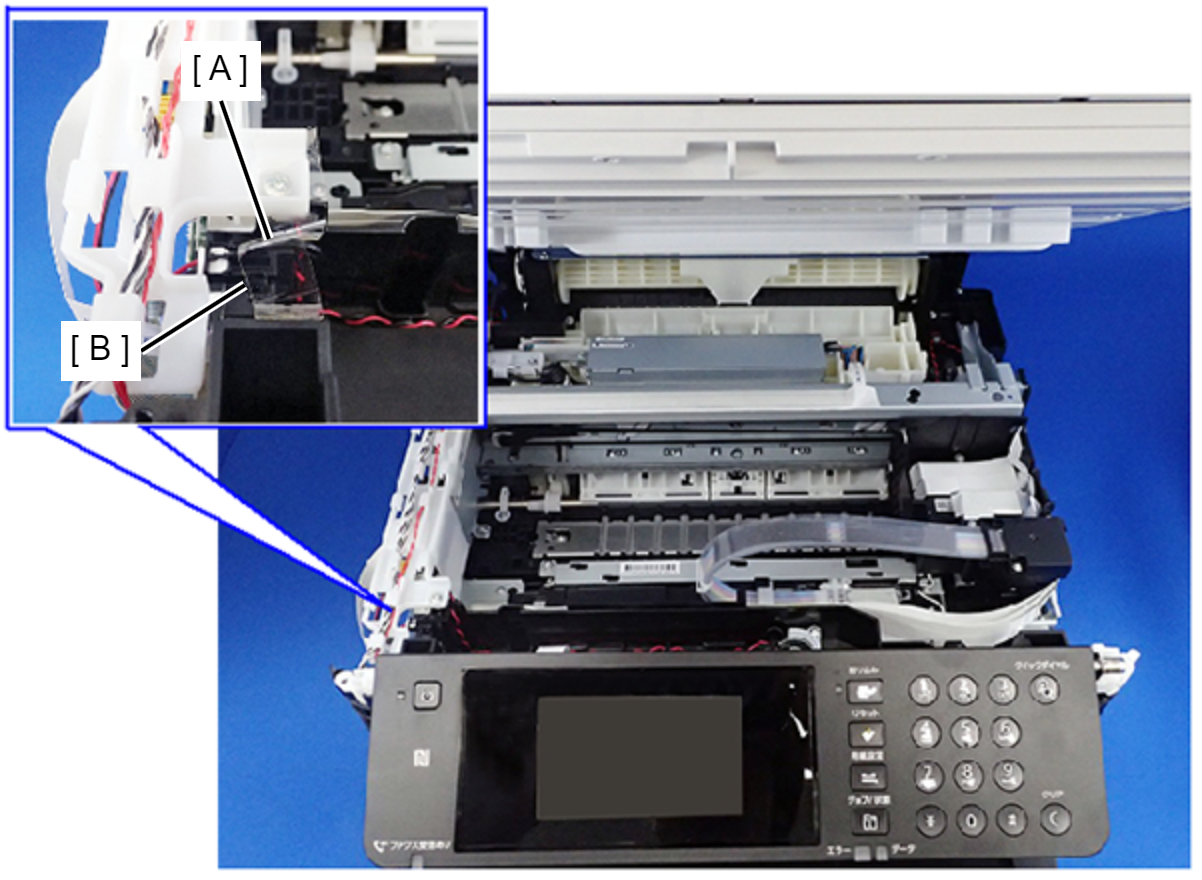
Head angular mecha adjustment must be performed when the ADF/SCN Unit has been opened.
Therefore, in order to set the ADF/SCN Open Sensor (A) to the closed state, secure it with tape (B).
Head angular mecha adjustment procedure flowchart
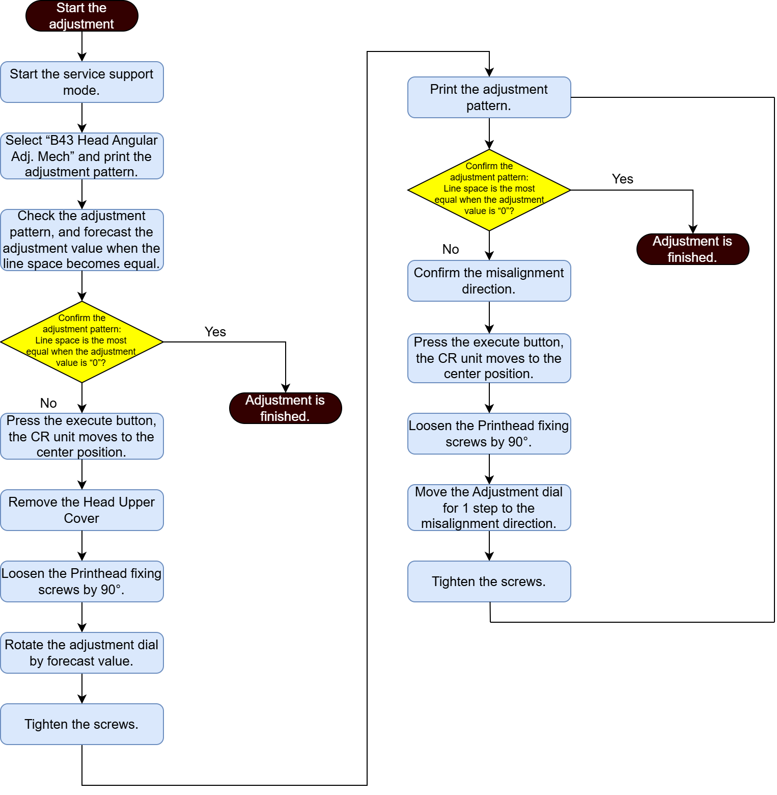
Method of the Head Angular Adjustment
Start the printer in the service mode.
Select “B43 Head Angular Adj. Mech” refer to “How to select an Adjustment item”.
Load specified paper into the specified paper feed tray.
- Confirm the current setting and print the adjustment pattern.
When changing the print setting, select and change the item following the instruction on the screen.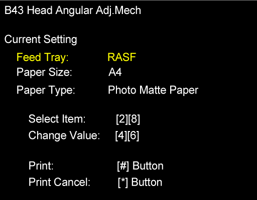
Check the adjustment pattern and determine the adjustment value based on the judgment procedure.
- B43 Head angular adj. mech pattern (Coarse adjustment pattern)
- B43 Head angular adj. mech pattern (Detail adjustment pattern)
 Check Point / チェックポイント
The following two types of patterns are printed in the adjustment pattern.
- Coarse adjustment pattern
The adjusted value is printed by five steps (-10, -5, 0, +5, +10). - Detail adjustment pattern
The adjusted value is printed by three steps (-5, -3, 0, +3, +5).
- Coarse adjustment pattern
- B43 Head angular adj. mech pattern (Coarse adjustment pattern)
- After printing the adjustment pattern, a confirmation screen shown below appears.If the adjustment is needed, follow the instructions on the screen.
After operation, the CR unit moves to the center part of the printer.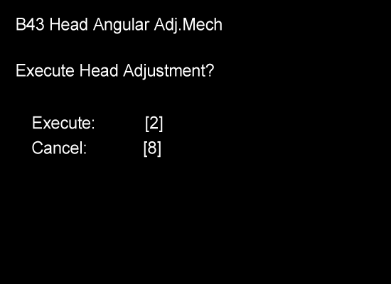
 Caution / 注意
If the tape of the ADF/SCN Open Sensor comes off during the adjustment, the CR Unit moves to the home position without the cover, so it is very dangerous. Therefore, make sure that the ADF/SCN Open Sensor is securely fixed in advance.
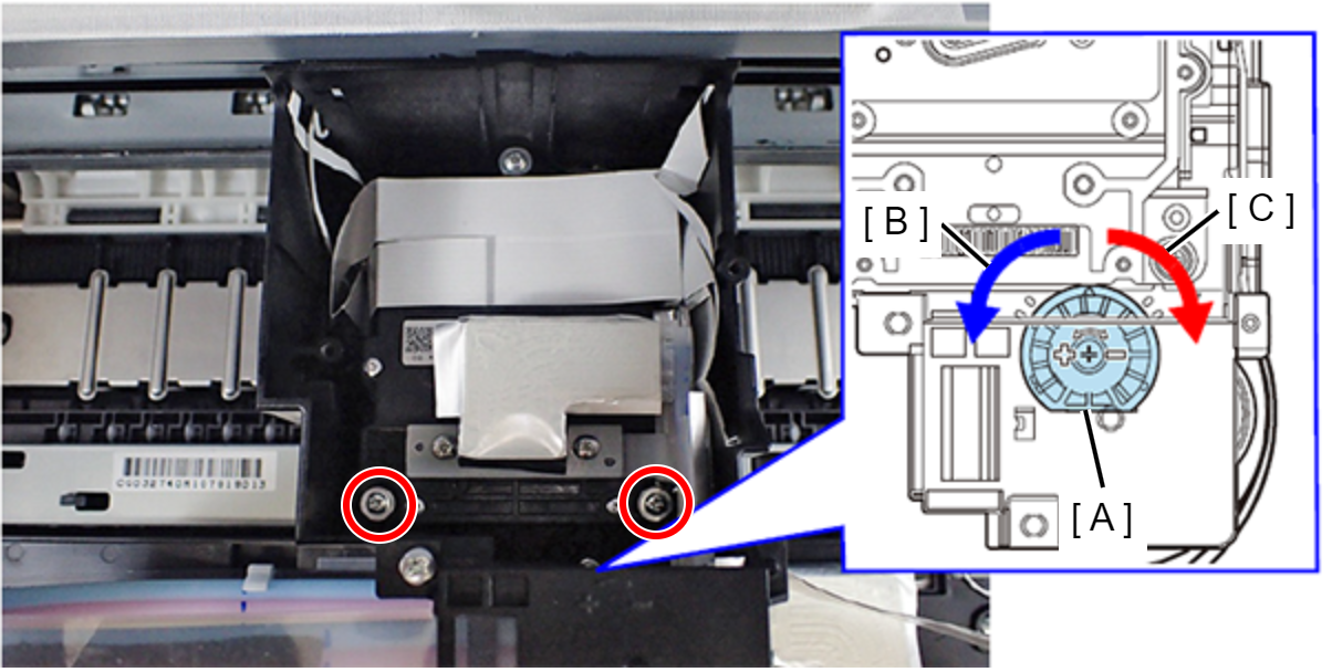
- Remove the screws (x2) that fix the Head Upper Cover and remove the Head Upper Cover. Turn the head screws (x3) that fix the Print Head counterclockwise by 90º to loosen them. Turn the adjustment dial based on the adjustment value confirmed in Step 5. (Blue arrow (B): + direction, red arrow (C): - direction)
- Tighten the head screws (x3).
- A confirmation screen shown below appears. Print the adjustment pattern again following the instruction on the screen.
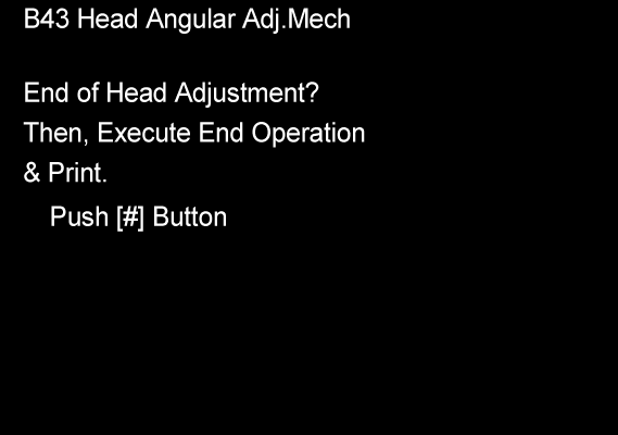
Check that the lines of the adjustment pattern of “0” are the most equal.
If the line spacing is equal: The adjustment is completed.
When not equal: Check the misalignment direction (“+”direction/“-” direction). Then go to Step 11.
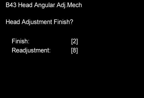
- Perform Step 6 to Step 7 and move the adjustment dial 1 notch in the direction confirmed in Step 10.
- Tighten the screws and print the adjustment pattern again to check whether the spacing between the pattern lines when the adjustment value is “0” is the evenest among the patterns.
If not, repeat steps Step 10 to Step 12 until the spacing of the pattern “0” becomes the evenest.Caution / 注意- After performing the Head Angular Adj. Mech, make sure to confirm the operation of the cap of the ink system as follows.
(If the cap does not return to its original position, capping cannot be performed accurately and printing failure may occur. For this reason, replace the Inksystem Assy.)
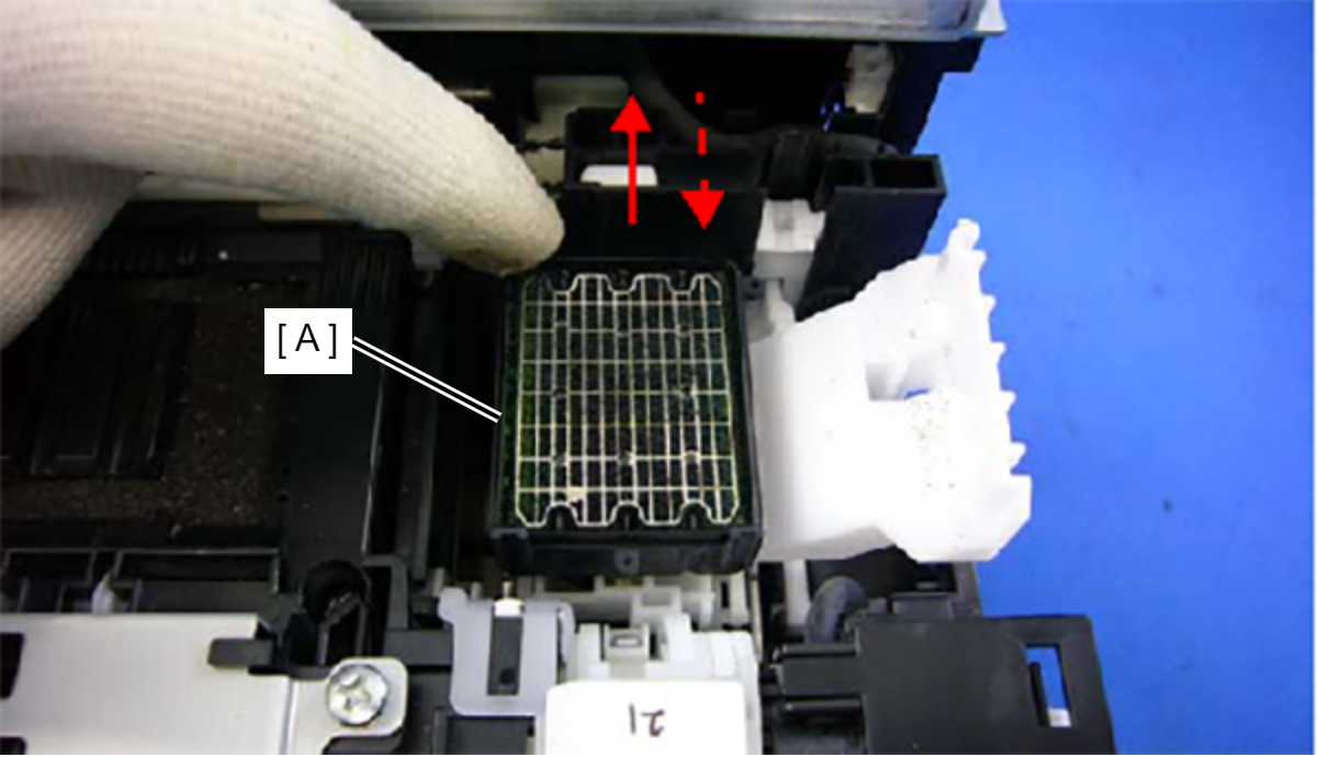
- Push the cap (A) to the rear of the printer as shown in the diagram below, and confirm it returns to its original position.
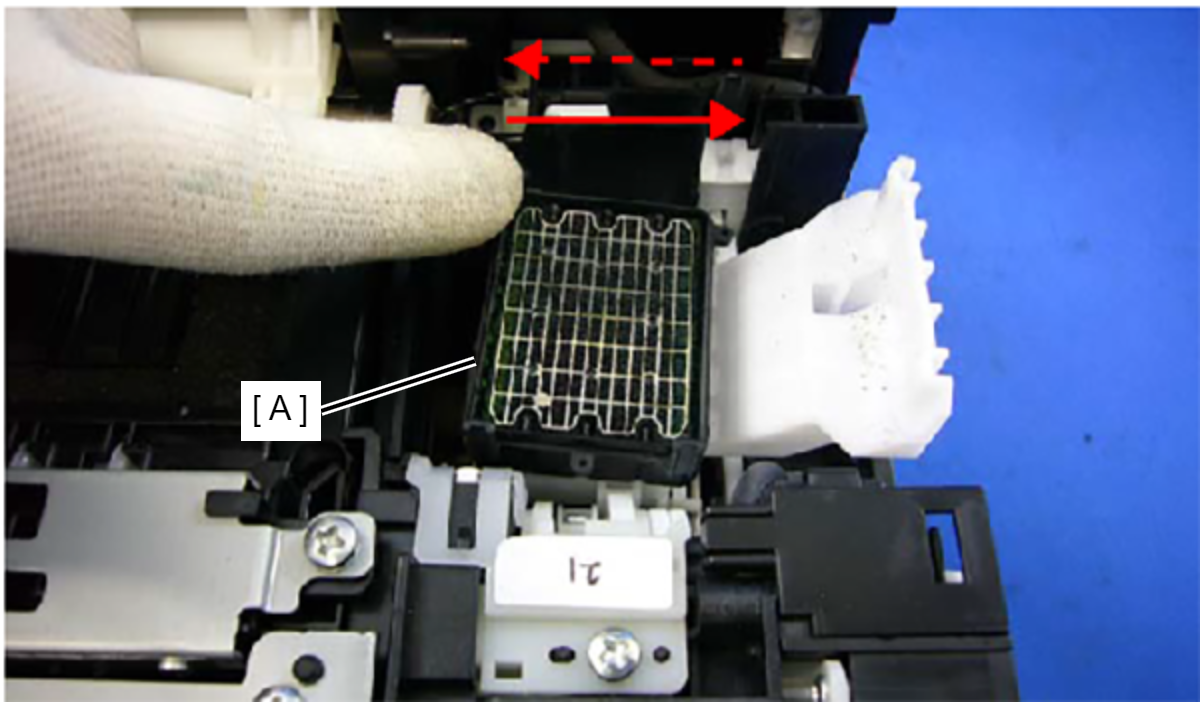
- Push the cap (A) over as shown in the diagram below, and confirm that it returns to its original position.
- After performing the Head Angular Adj. Mech, make sure to confirm the operation of the cap of the ink system as follows.