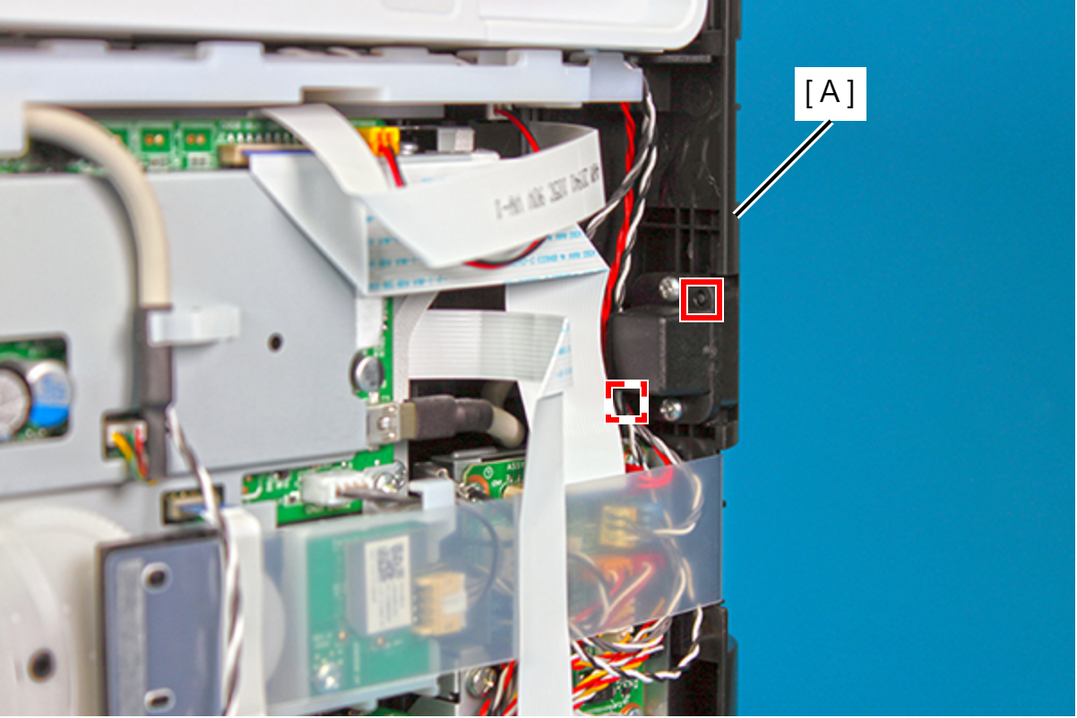
USB Interface Board
- Remove the four screws, then remove the Rear Cover (Back) (A).
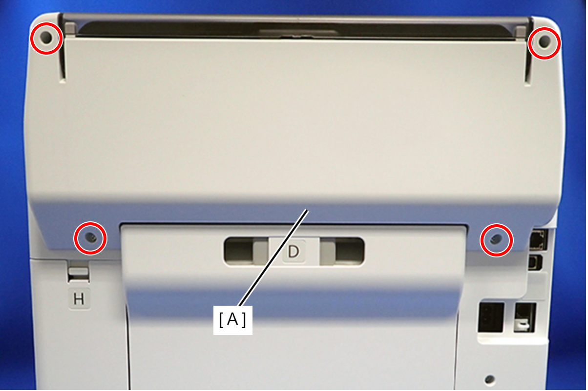
 : C.B.P-TITE-SCREW-3x10-F.ZN-3C
 Assembly / 組み立て
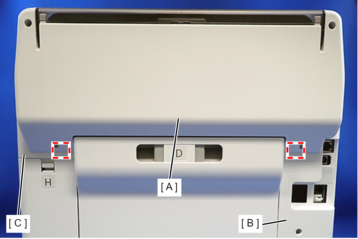
Attach the two dowels of the Rear Cover (Back) (A) to the positioning holes on the Housing Left (B) and Housing Right (C).
- Remove the two screws, then remove the Rear Top Cover (A).
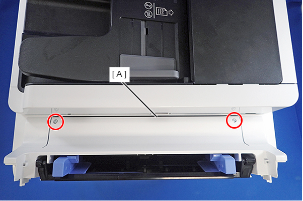
- : C.B.P-TITE-SCREW-3x10-F.ZN-3C
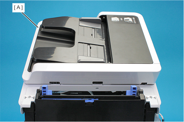
- Open the ADF/SCN Unit (A).
- Remove the three screws that secure the Housing Left (A).
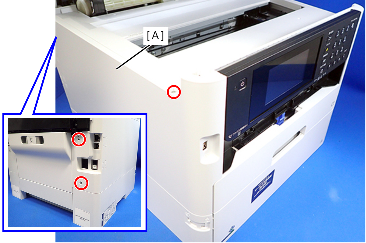
- : C.B.P-TITE-SCREW-3x10-F.ZN-3C
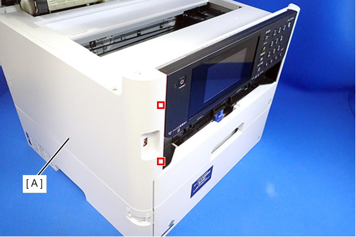
- Lift the Housing Left (A) to release the two hooks on the front side of the Housing Left.
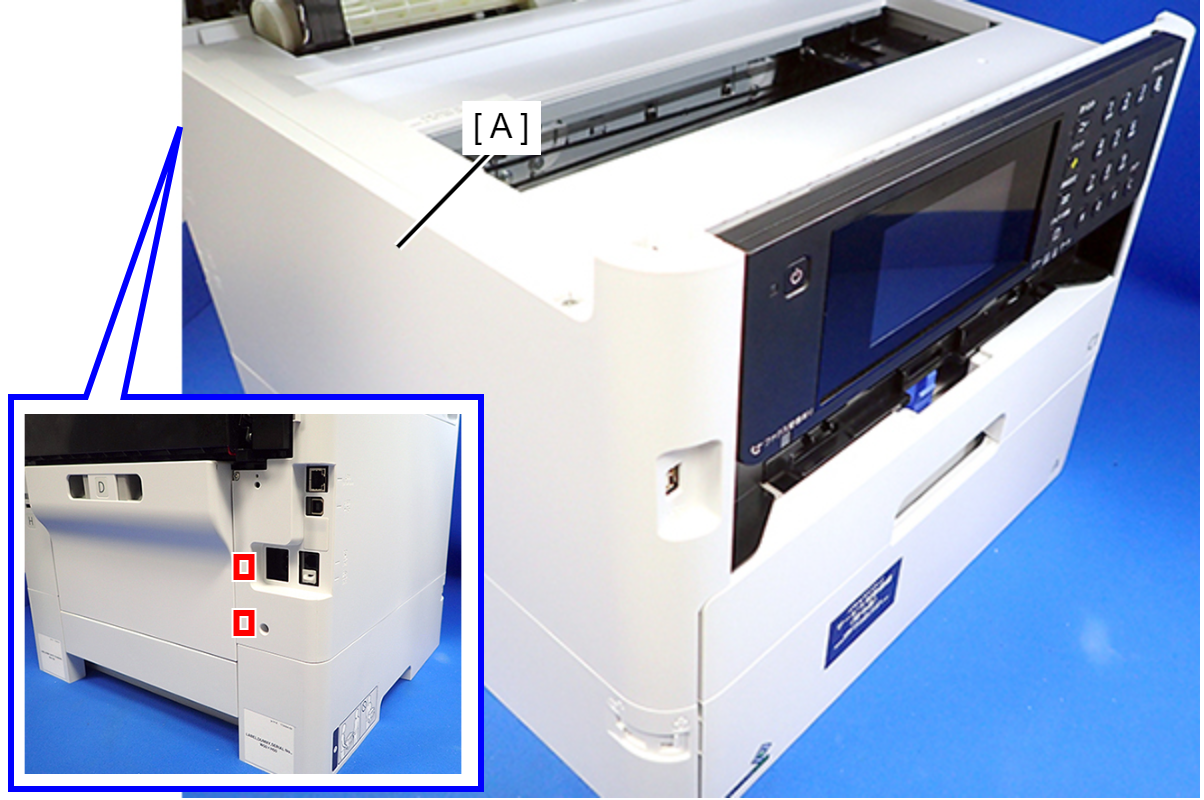
- Disengage two hooks on the rear side of the Housing Left (A), and remove the Housing Left (A).
 Assembly / 組み立て
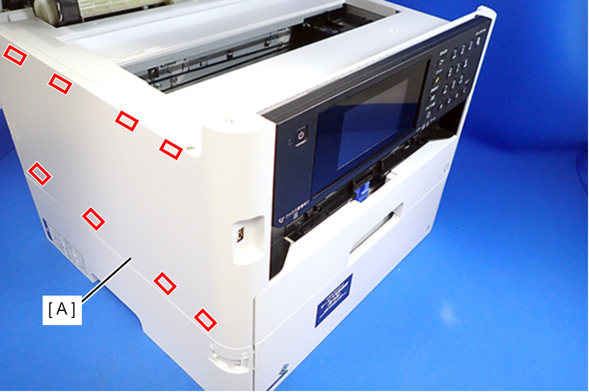
Insert the eight tabs on the Housing Left (A) to the positioning holes of the Housing Upper (B) and the RIPS Unit (C).
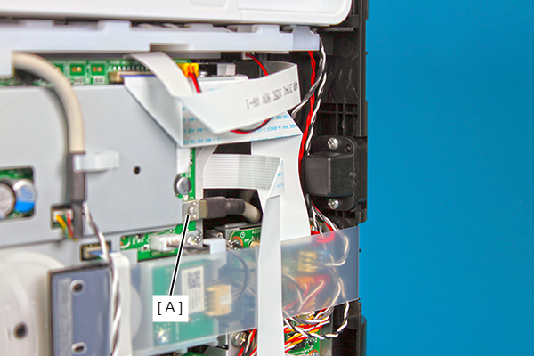
- Disconnect the cable from CN33 (A) of the Main Board.
- Remove the two screws, then remove the USB Interface Board (B) from the Housing Front (A).
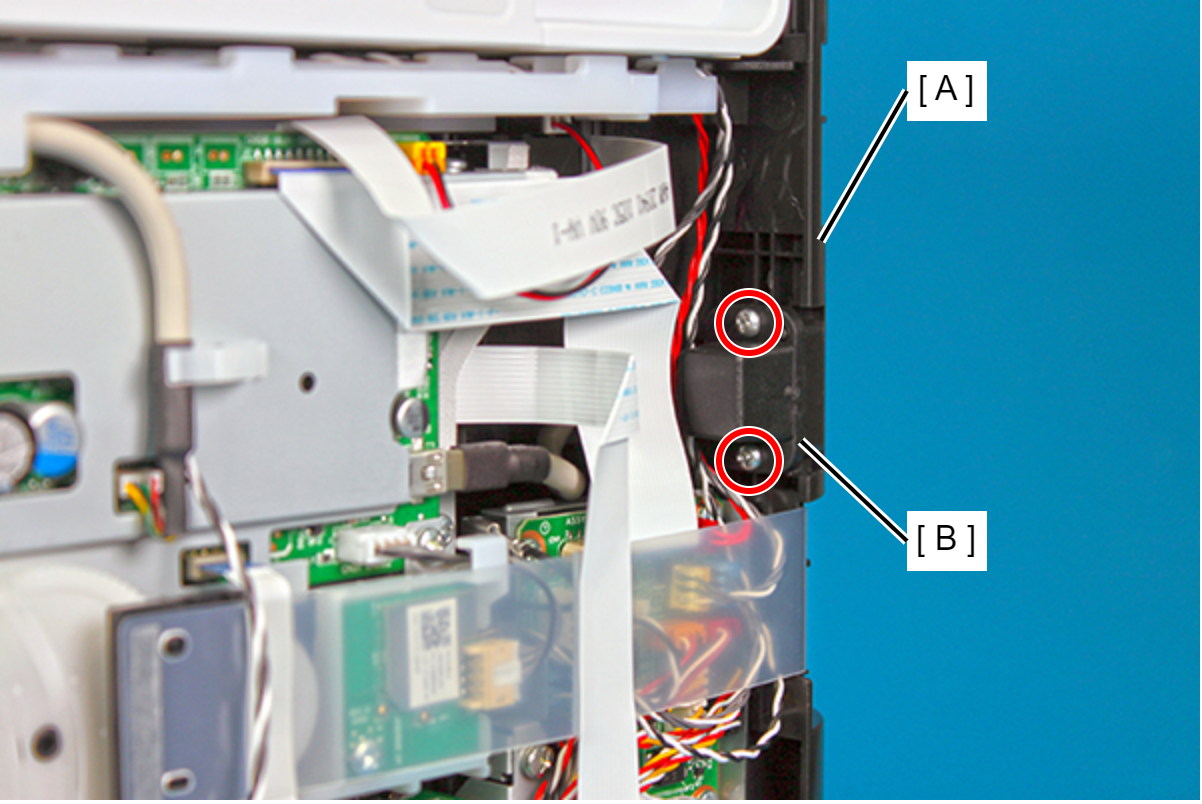
 : C.B.P-TITE-SCREW-3x10-F.ZN-3C
Assembly / 組み立てMake sure to align the positioning holes on the USB Interface Board with the dowels on the Housing Front (A).