
Numpad Board Assy
- Remove the four screws, then remove the Rear Cover (Back) (A).
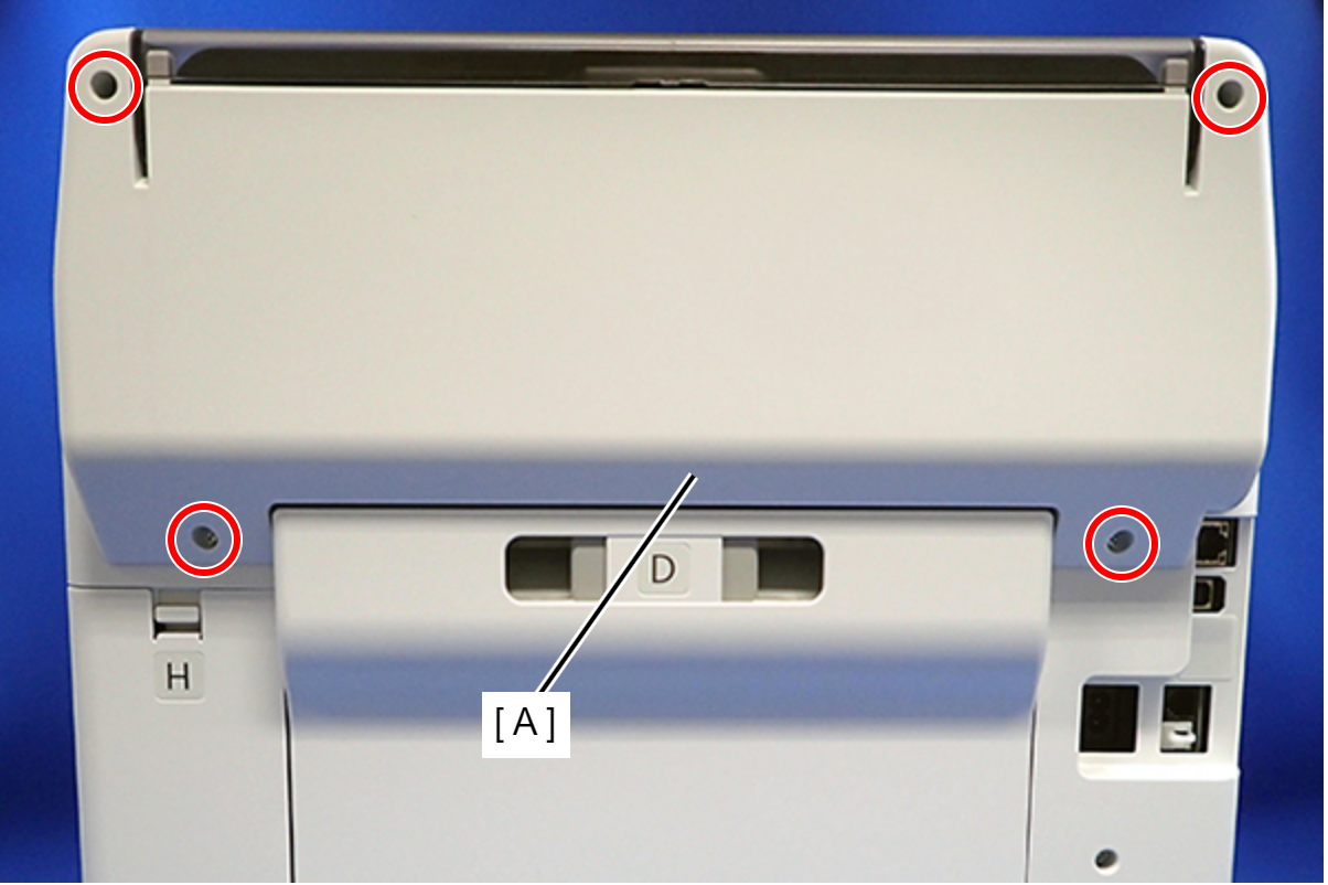
 : C.B.P-TITE-SCREW-3x10-F.ZN-3C
 Assembly / 組み立て
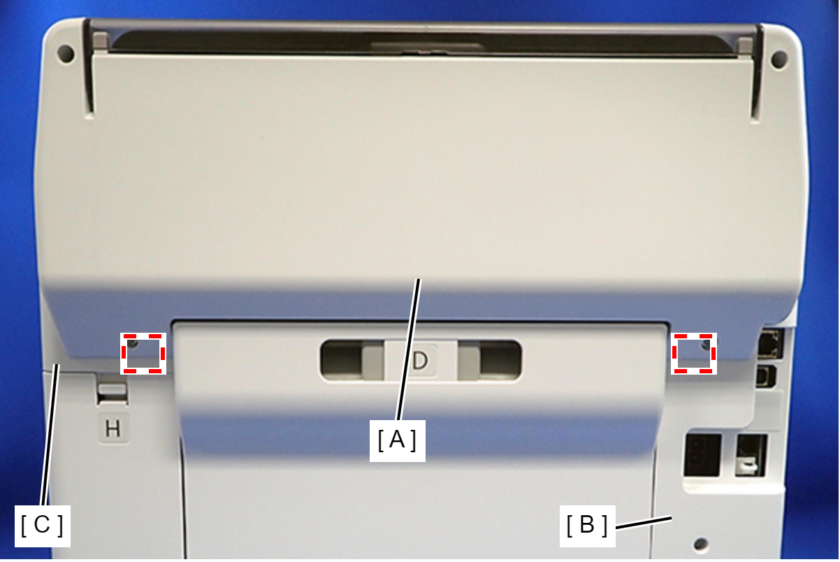
Attach the two dowels of the Rear Cover (Back) (A) to the positioning holes on the Housing Left (B) and Housing Right (C).
- Remove the two screws, then remove the Rear Top Cover (A).
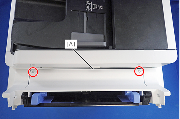
- : C.B.P-TITE-SCREW-3x10-F.ZN-3C
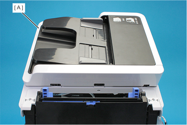
- Open the ADF/SCN Unit (A).
- Remove the three screws that secure the Housing Left (A).
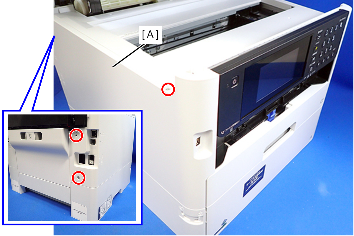
- : C.B.P-TITE-SCREW-3x10-F.ZN-3C
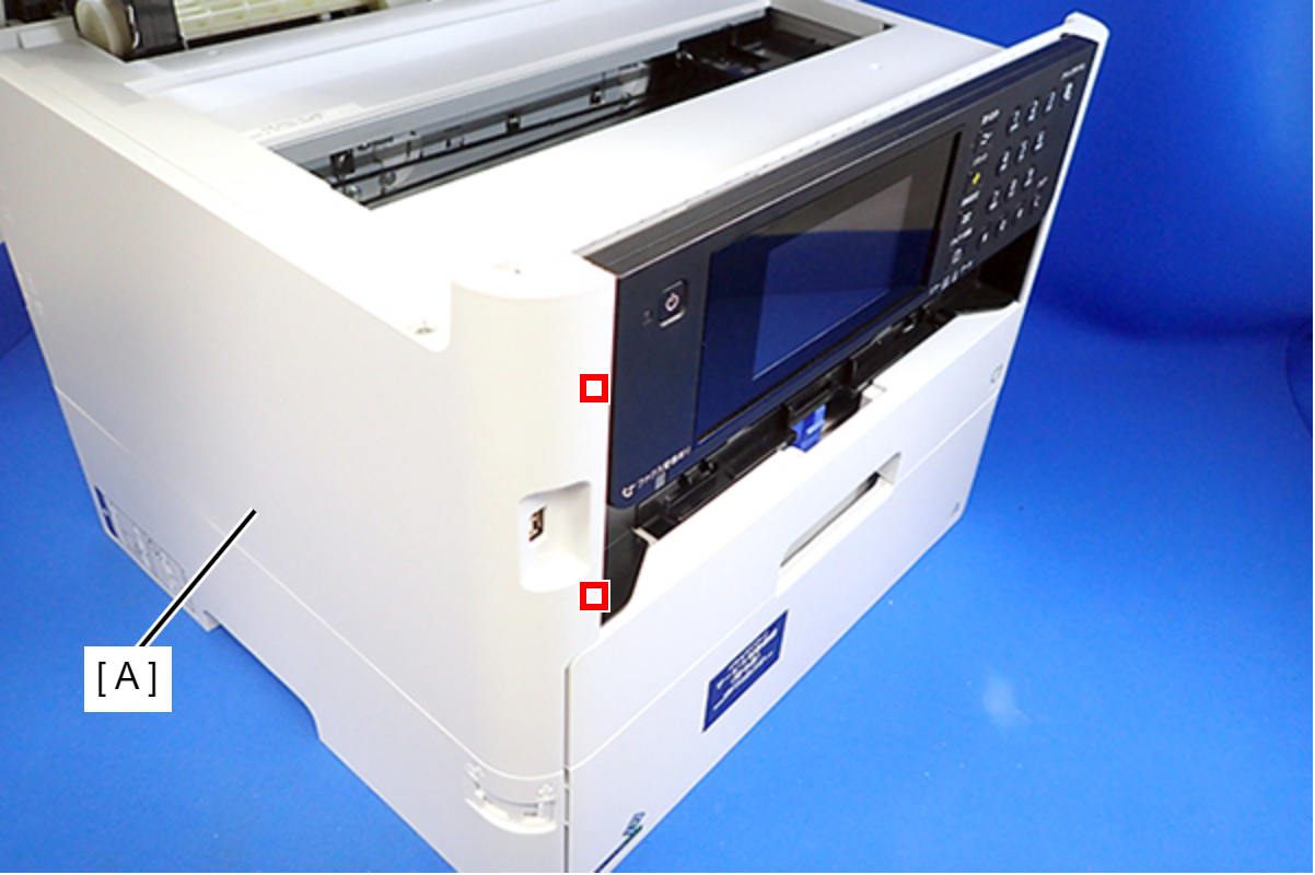
- Lift the Housing Left (A) to release the two hooks on the front side of the Housing Left.
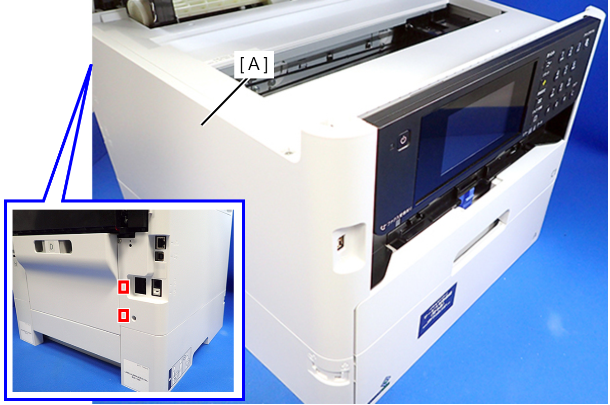
- Disengage two hooks on the rear side of the Housing Left (A), and remove the Housing Left (A).
 Assembly / 組み立て
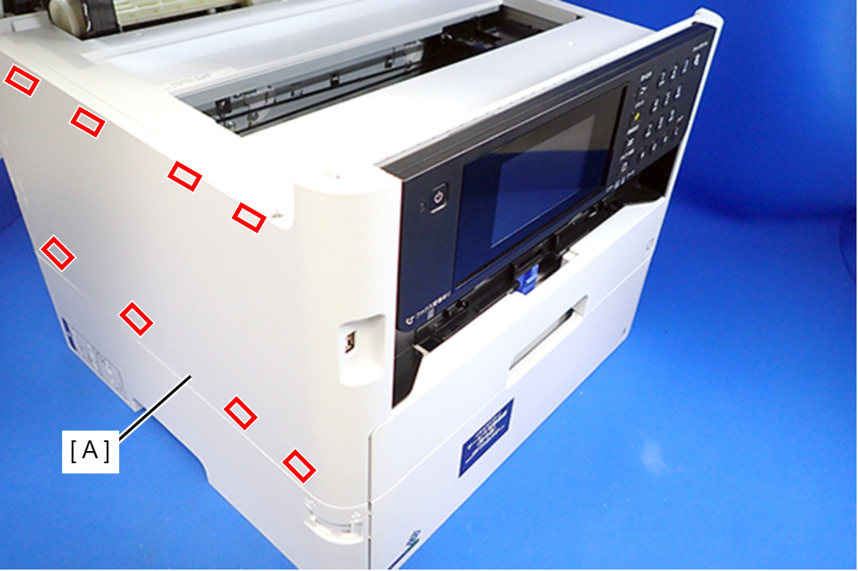
Insert the eight tabs on the Housing Left (A) to the positioning holes of the Housing Upper (B) and the RIPS Unit (C).
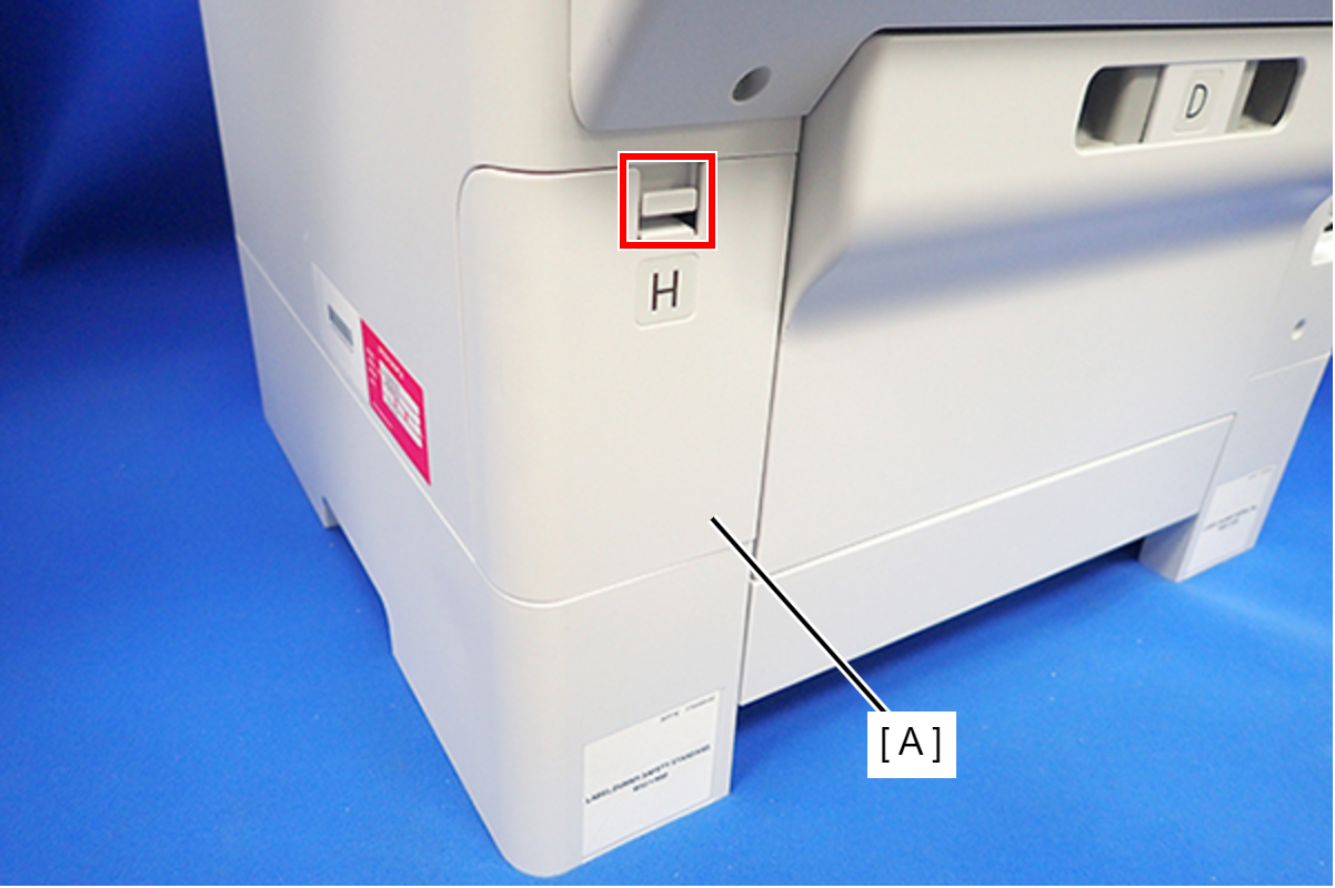
- Disengage the hook, and remove the Maintenance Box Cover (A).
- Open the ADF/SCN Unit (A).
- Remove the four screws that secure the Housing Right (A).
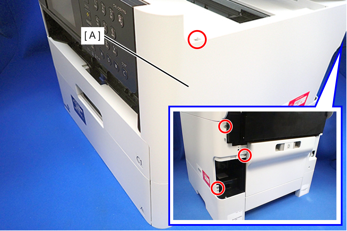
- : C.B.P-TITE-SCREW-3x10-F.ZN-3C
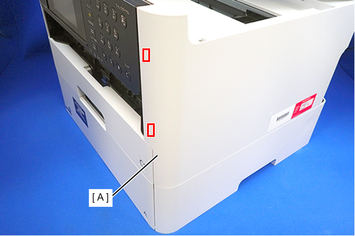
- Lift the Housing Right to release the two hooks on the front side of the Housing Right, then remove the Housing Right.
 Assembly / 組み立て
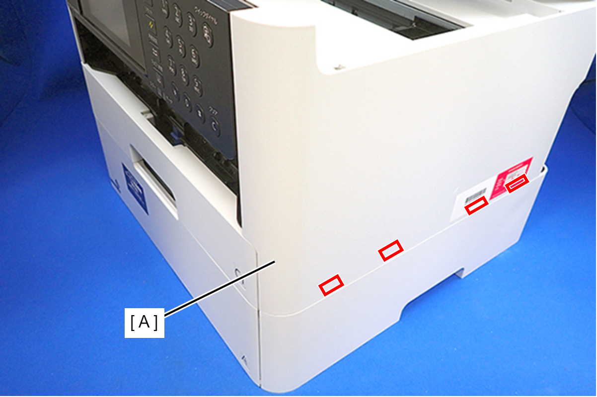
Insert the four tabs of the Housing Right (A) to the positioning holes on the Ink Supply Unit.
- Remove the six screws, then remove the Housing Upper (A).
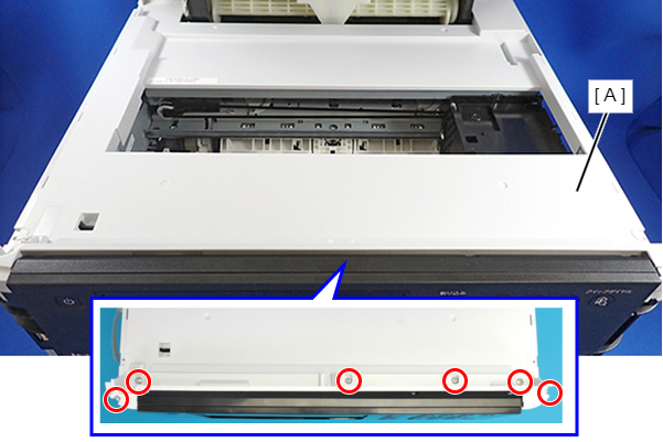
- : C.B.P-TITE-SCREW-3x10-F/ZN-3C
- Release the all cable from the Cable Guide (A).
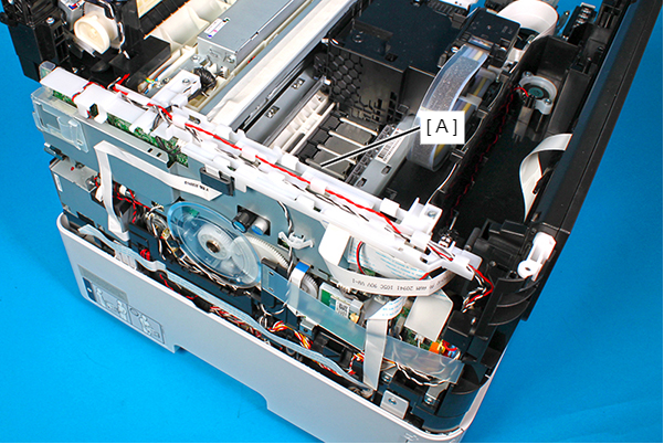
- Remove the two screws, and remove the Cable Guide (A).
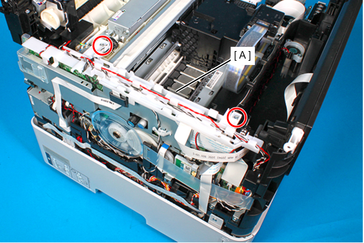
 : C.B.P-TITE-SCREW-3x10-F.ZN-3C
Assembly / 組み立て- Route the PS cable (A) through the two guides and hook on the Cable Guide.
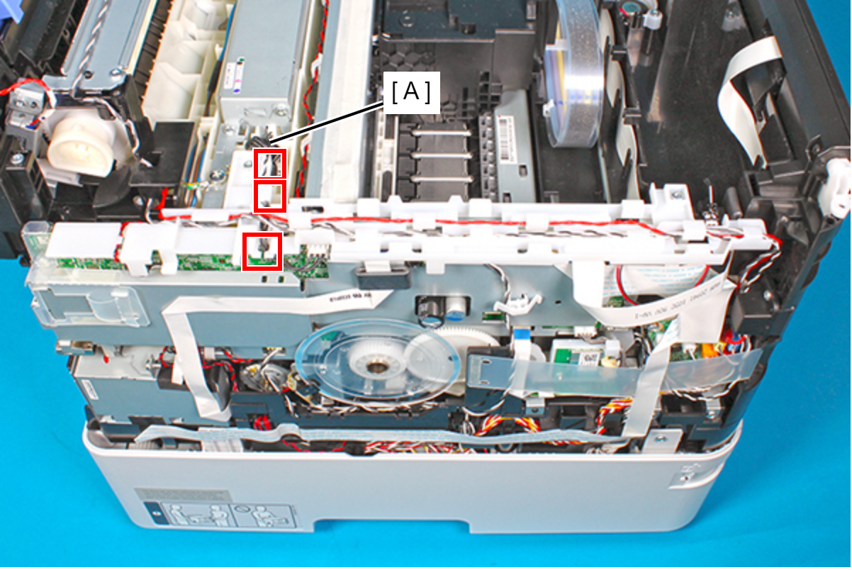
- Route the Rear ASF Solenoid cable (A) through the six hooks on the Cable Guide.
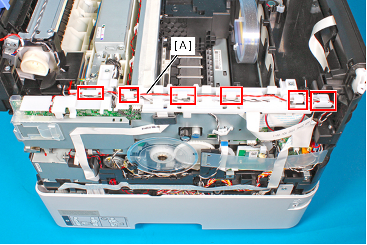
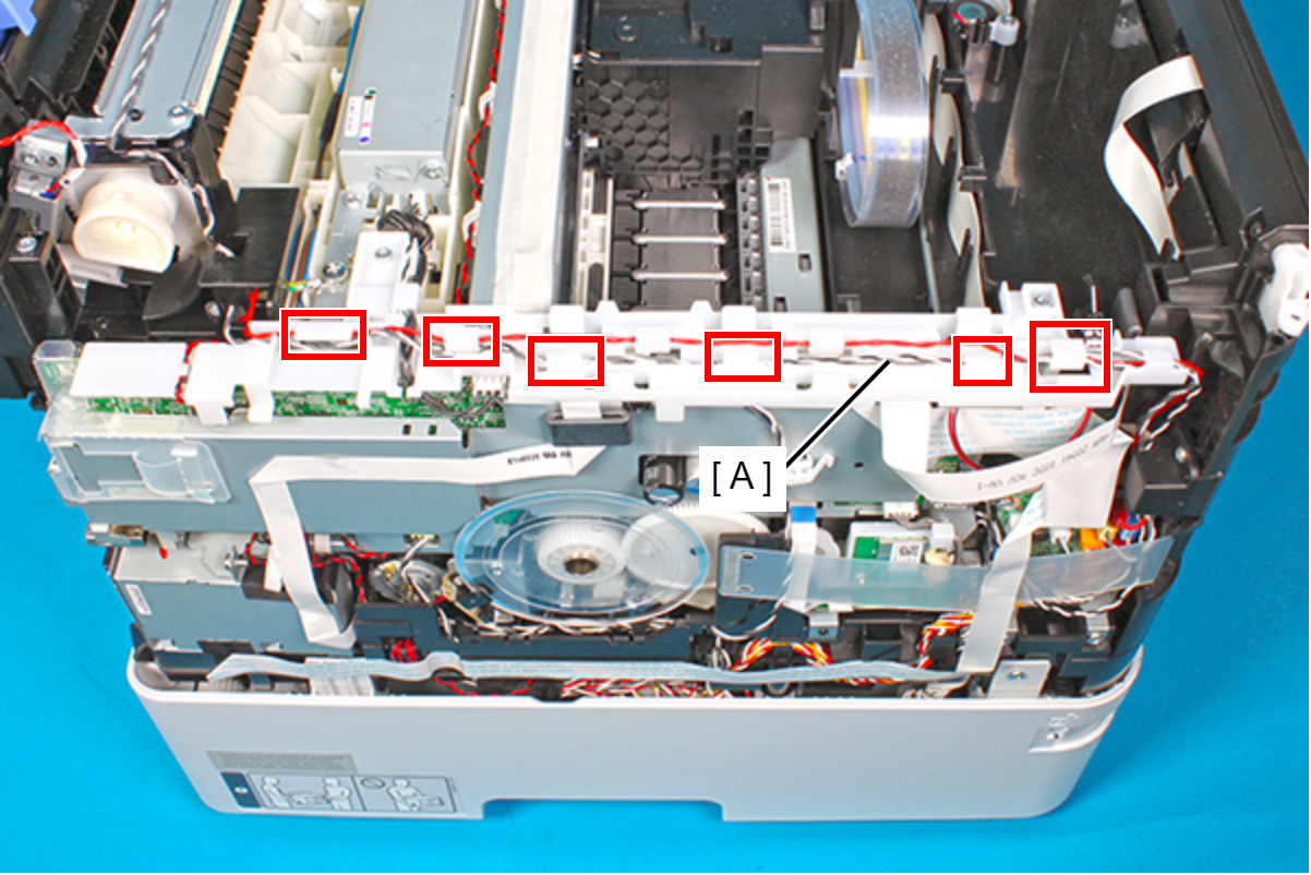
- Route the Rear Unit Detection Sensor cable and Rear ASF Paper Detection Sensor cable (A) through the three hooks and the three hooks on the Cable Guide.
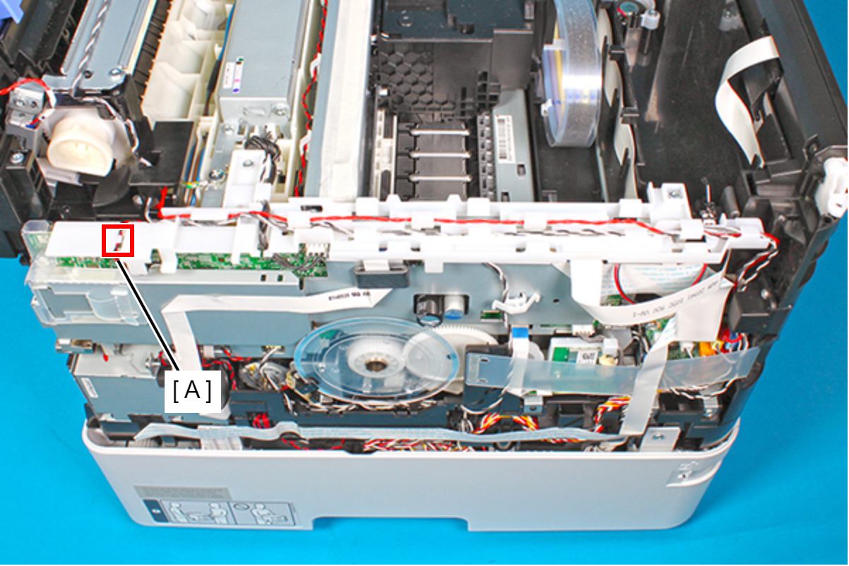
- Route the ASF motor cable (A) through the guide on the Cable Guide.
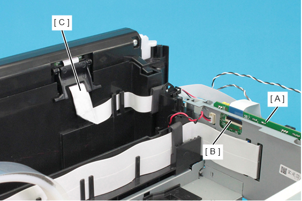
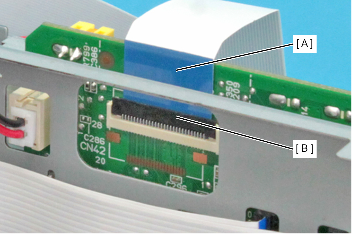
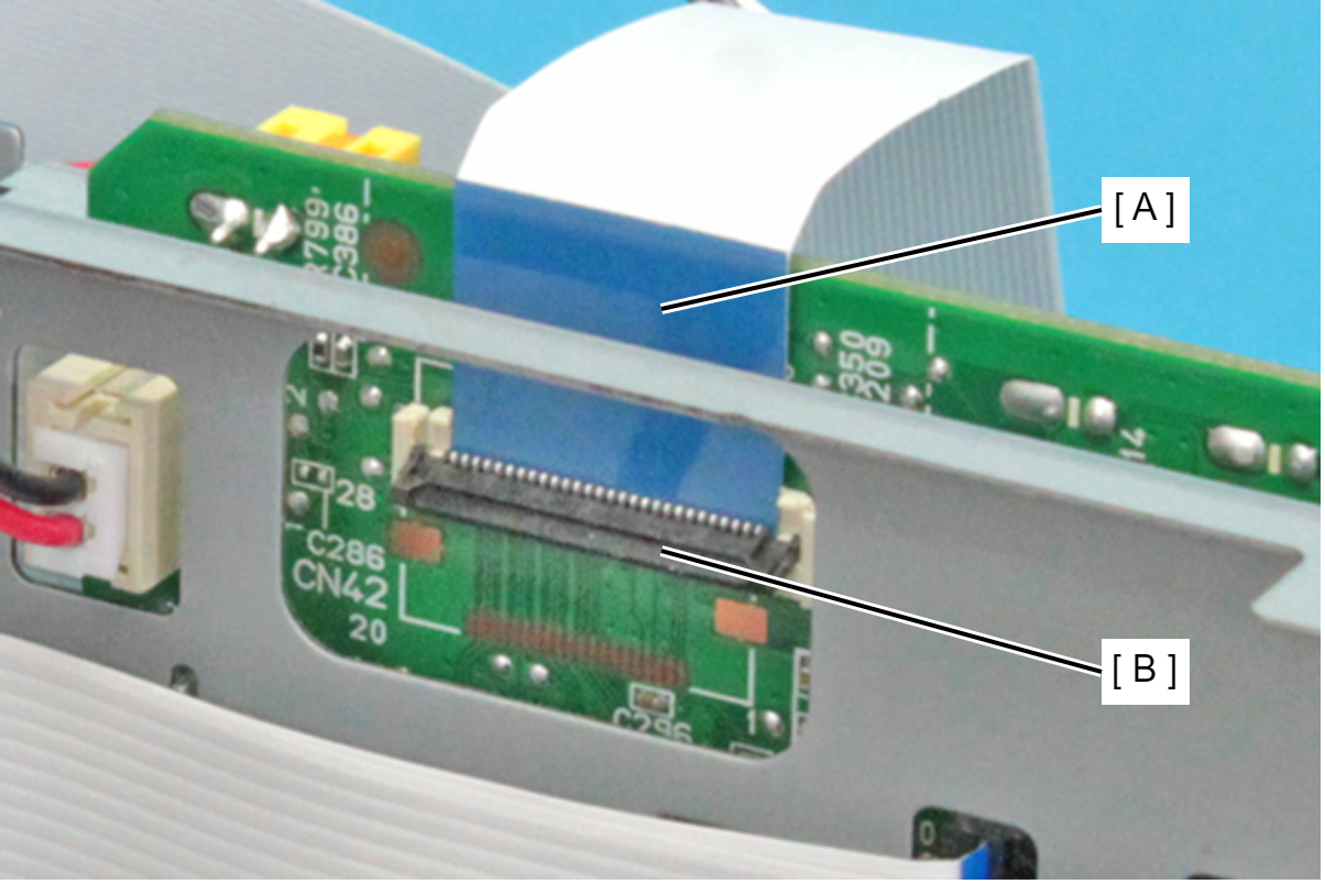
- Disconnect the FFC (C) from the connector (CN42) (B) on the Main Board Assy (A).
 Check Point / チェックポイント
When disconnecting the FFC (A), make sure to unlock the connector lock (B) beforehand.
- Close
- Open
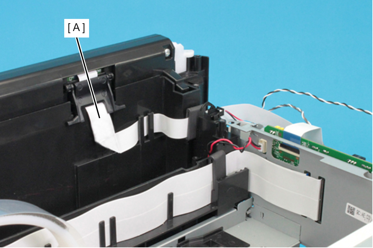
- Peel off the FFC (A) from the Frame Base.
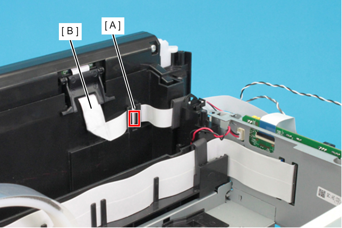
- Release the FFC (B) from two tabs (A) on the Frame Base.
 Assembly / 組み立て
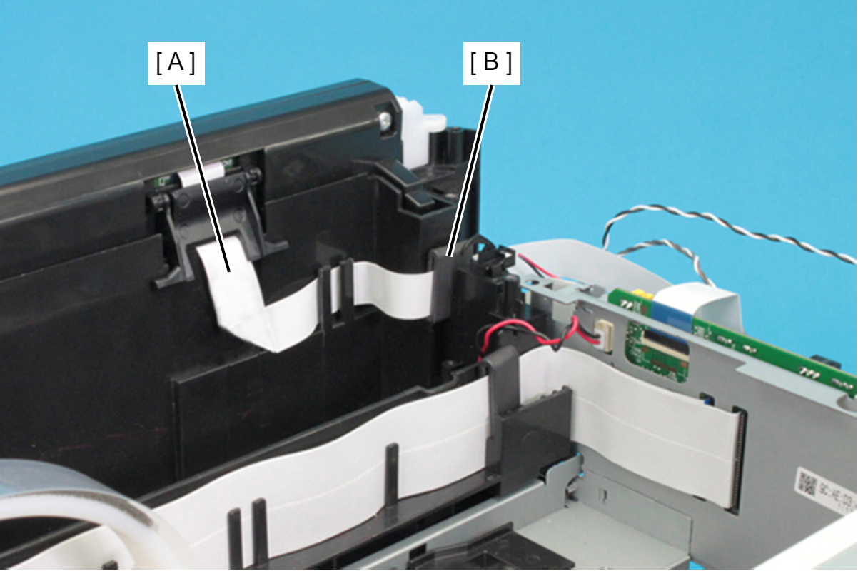
Set the ferrite core (B) of the FFC (A) in the point shown below.
- Remove the two screws, then remove the Right Panel Holder (A).
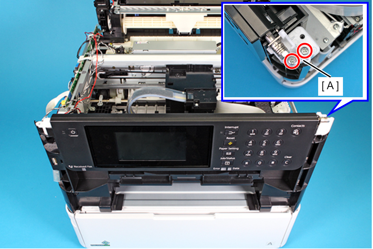
- : C.B.P-TITE-SCREW-3x10-F.ZN-3C
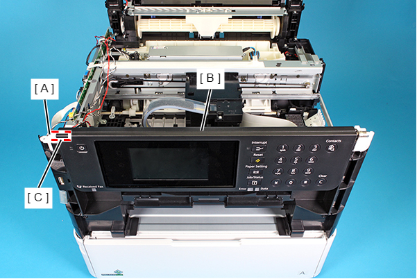
- Release the shaft (C) of the Panel Assy (B) from bearing (A), then remove the Panel Assy (B).
- Remove the six screws that secure the Panel Housing.
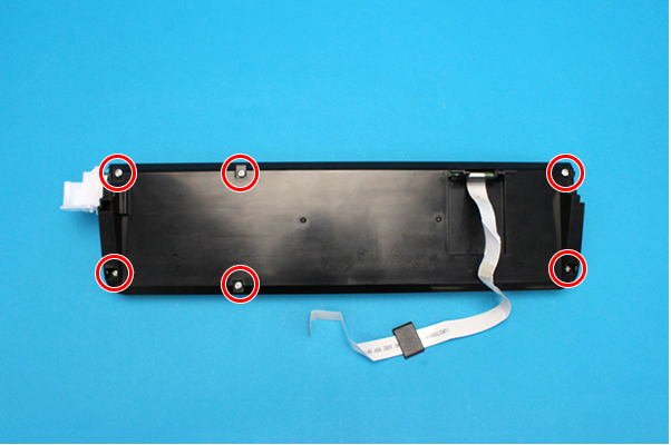
- : C.B.P-TITE-SCREW-3x10-F.ZN-3C
- Disengage three hooks on the Panel Housing, and remove the Panel Housing.
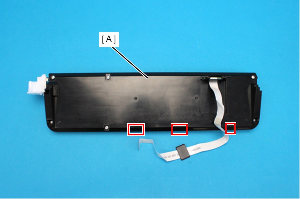
Remove the Panel FFC Cover (A).
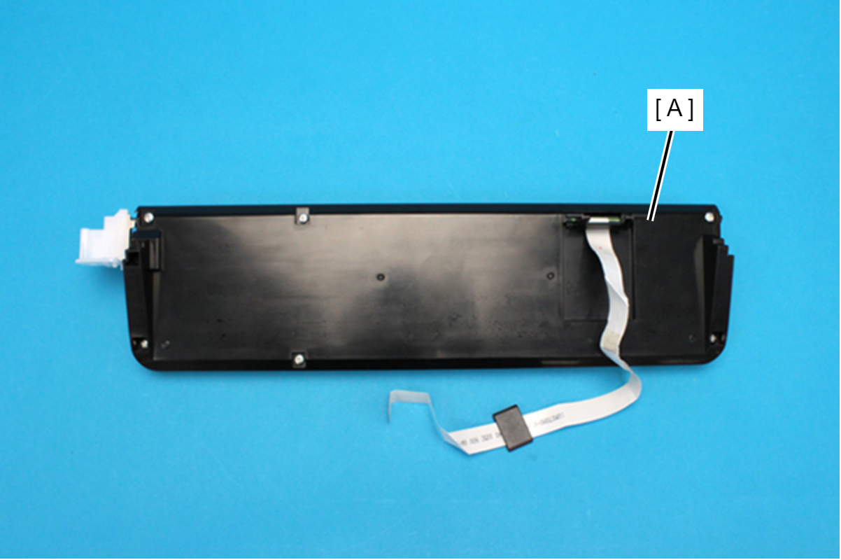 Assembly / 組み立て
- Install the Panel FFC Cover (A) as shown below.
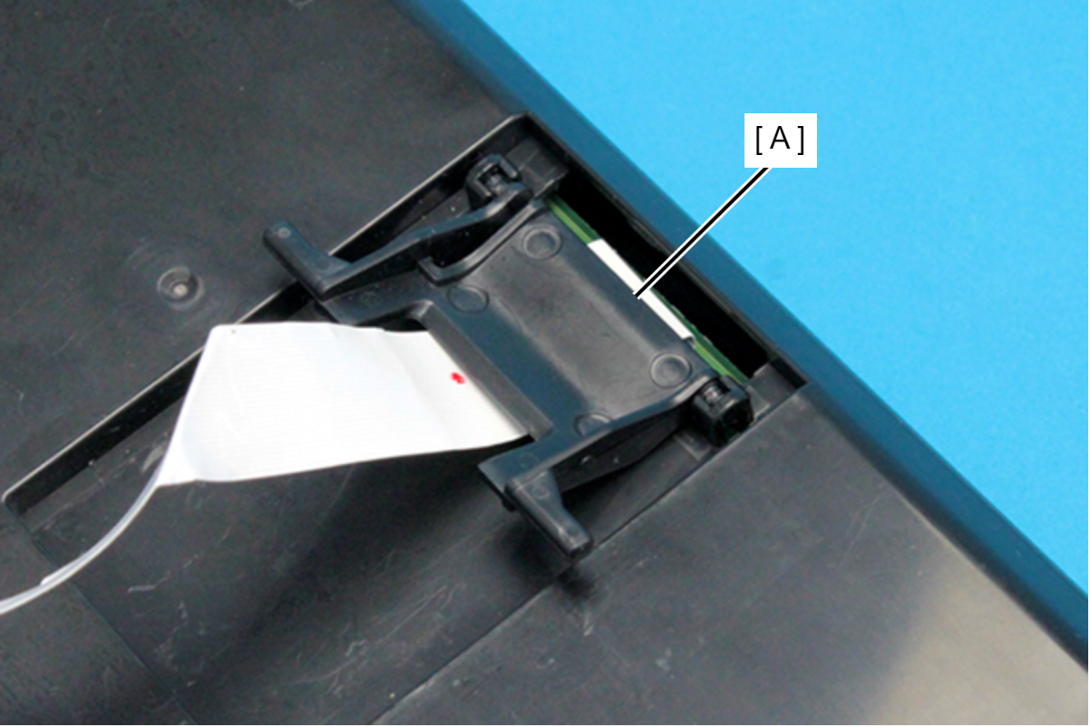
- Install the Panel FFC Cover (A) as shown below.
- Pull the Relay Cable out from the hole of the Panel Housing.
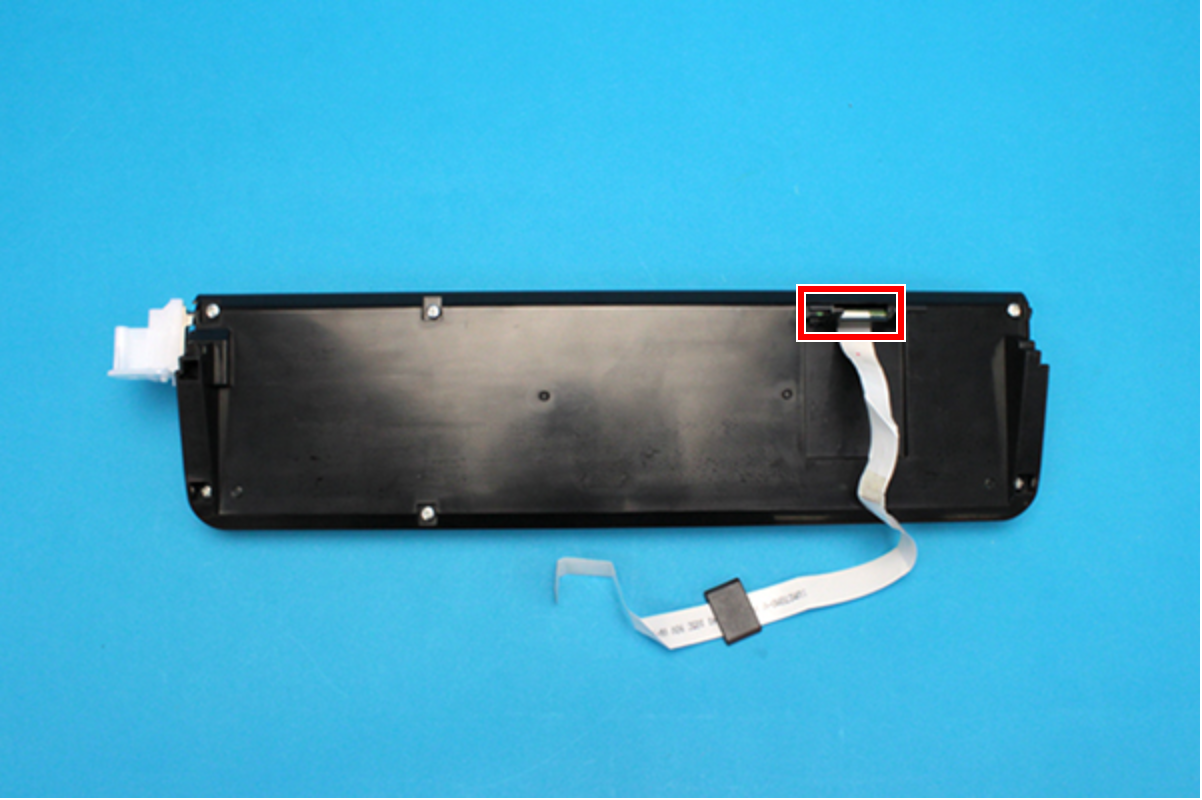
- Peel off the double-sided tape, and disconnect the FFC (B) from the connector (CN311) on the Panel Board (A).
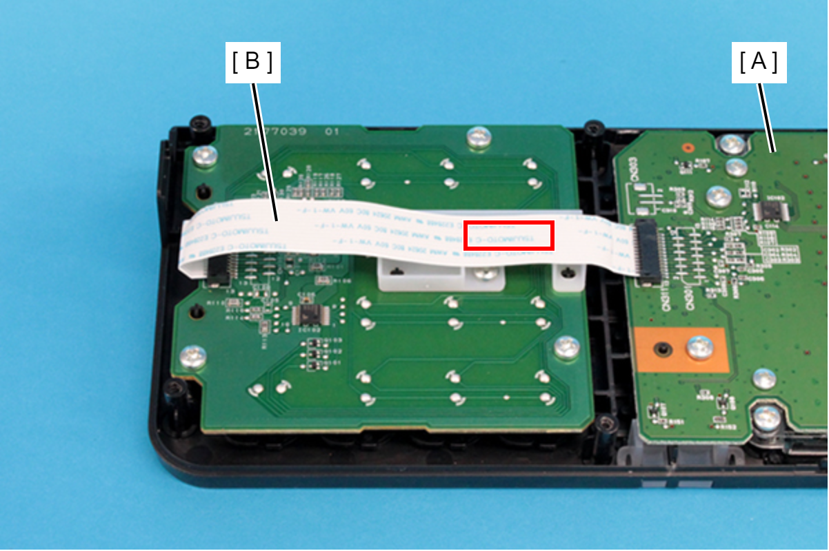
- Remove the screw, and remove the FFC cover (A).
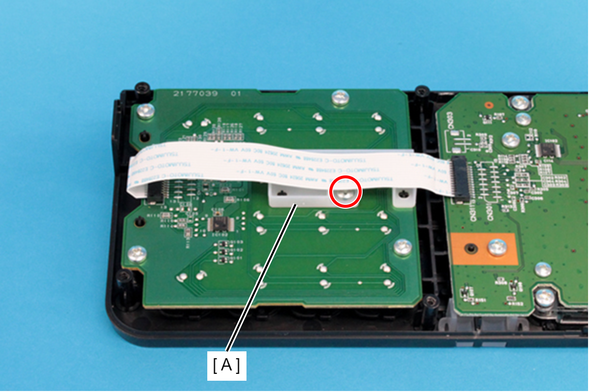
- : C.B.P-TITE-SCREW-3x10-F.ZN-3C
- Remove the four screws, and remove the Numpad Board Assy (A).
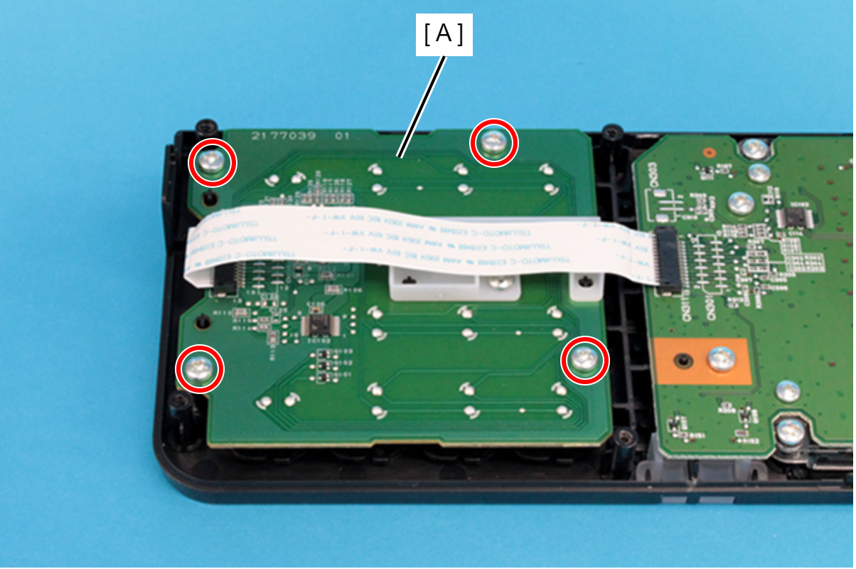
- : C.B.P-TITE-SCREW-3x10-F.ZN-3C