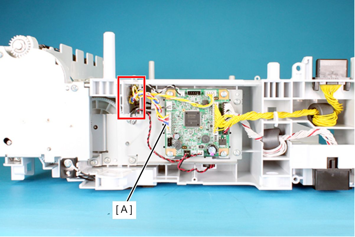
Sensor Cable
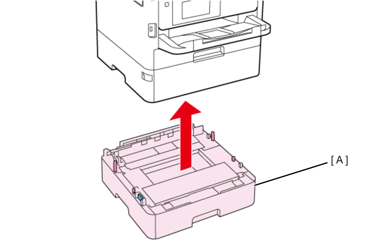
- Lift the printer, then remove the Optional Paper Cassette (A).
 Assembly / 組み立て
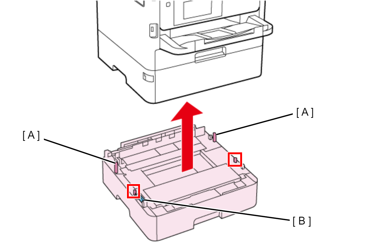
When attaching the Optional Paper Cassette, be sure to align the positioning pins (A) (x2) and the dowels so as to avoid damage to the Drawer Connector (B).
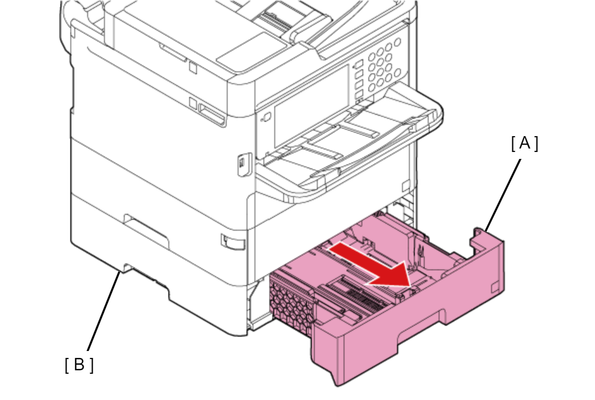
- Pull the Paper Cassette 2 (A), then remove it from the Optional Paper Cassette Unit (B).
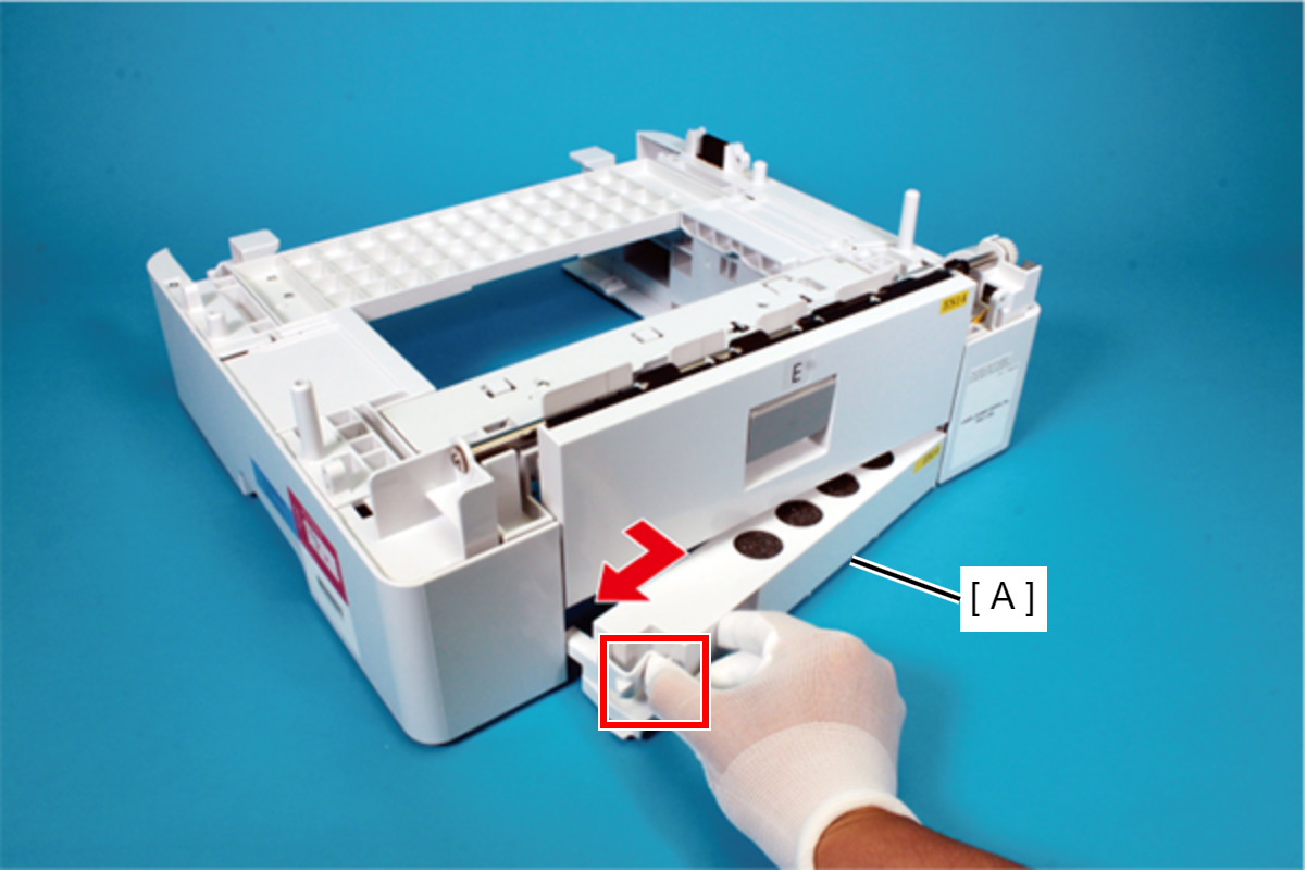
Pick the tab, and remove the Rear Lower Cover Assy (A) in the direction of the arrow.
 Assembly / 組み立て
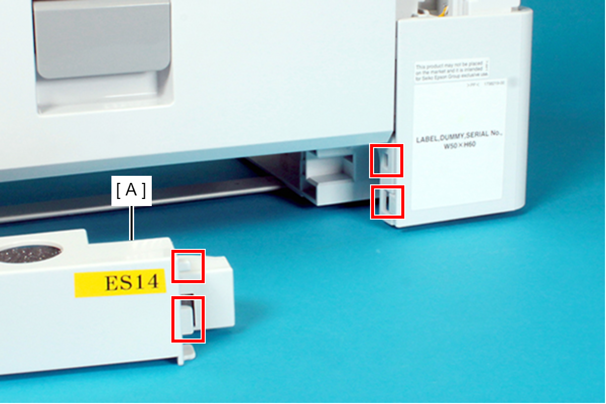
When installing the Rear Lower Cover Assy (A), attach the two ribs of the Rear Lower Cover Assy (A) to the holes of the frame.
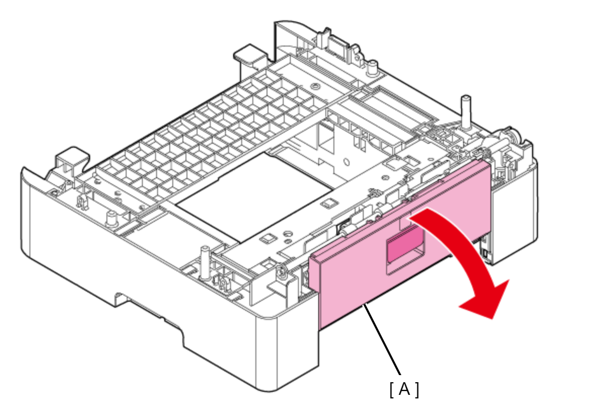
- Open the Rear Cover (A).
- Remove the screw that secure the Rear Cover Band (A) to the Rear Frame (B).
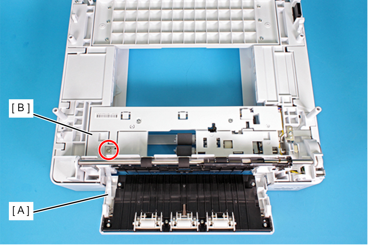
 : C.B.P-TITE-SCREW-3x10-F.ZN-3C
- Push the Rear Cover (A) in the direction of the arrow, and remove dowel A of the Rear Cover (A) from the hole in the frame.
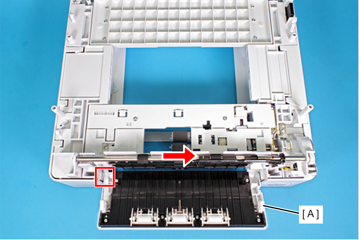
- Remove dowel A (B) of the Rear Lower Cover (A) along the groove of the frame.
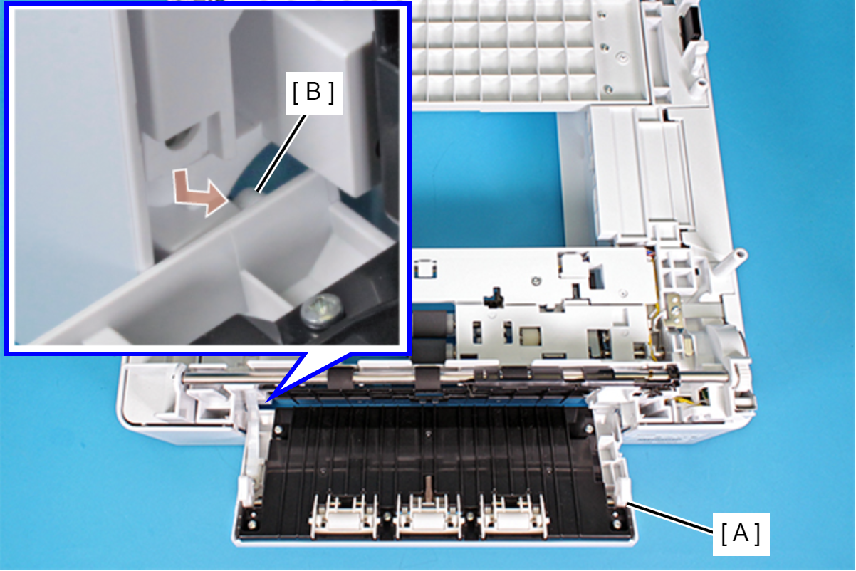
- Remove dowel B of the Rear Lower Cover (A) from the hole in the frame, and then remove the Rear Cover (A).
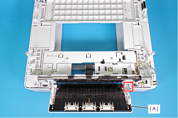
Assembly / 組み立て- When attaching the Rear Lower Cover, first of all, attach dowel B in the hole of the frame.
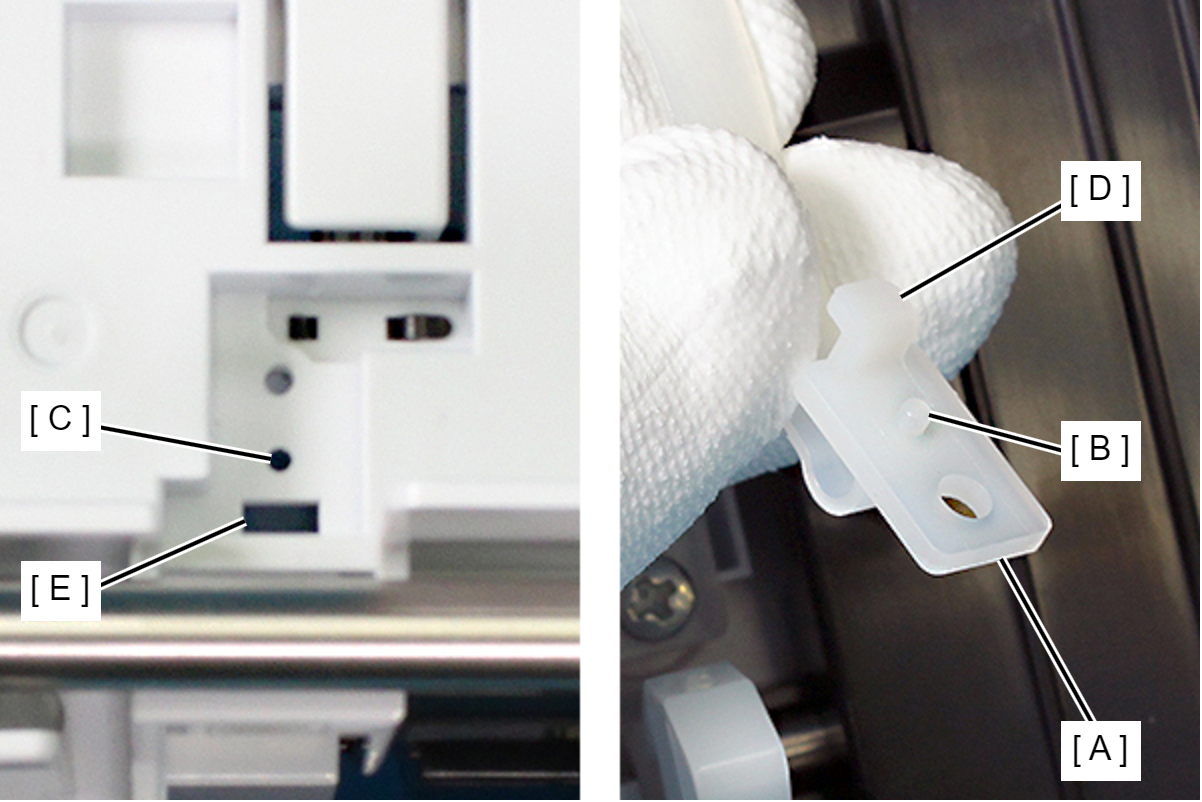
- When attaching the Rear Cover Band (A), make sure to align the dowel (B) with the hole1 (C) first, then engage the hook (D) to the hole 2 (E), and finally secure with the screw.
- Remove 3 screws.
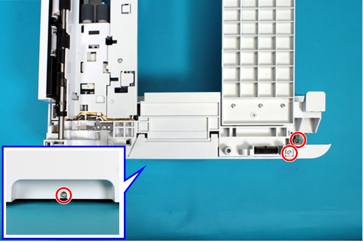
- : C.B.P-TITE-SCREW-3x10-F.ZN-3C
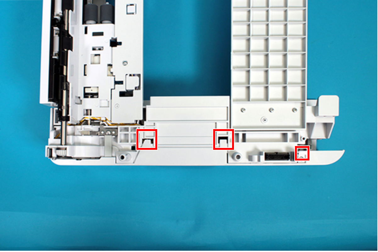
- Disengage the dowel and two hooks at the top.
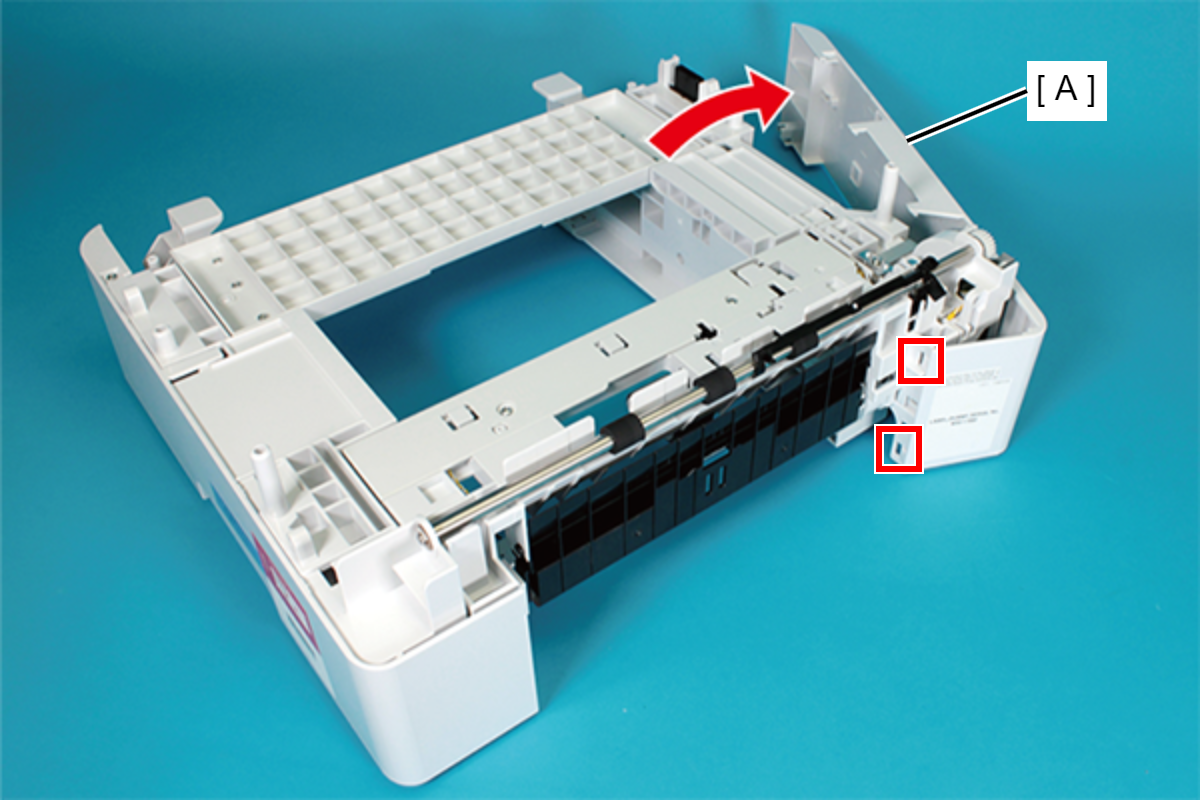
- Rotate in the direction of the arrow, disengage the hooks (x2) on the rear side, and then remove the Left Cover (A).
- Remove the two screws and remove the Middle Frame (A).
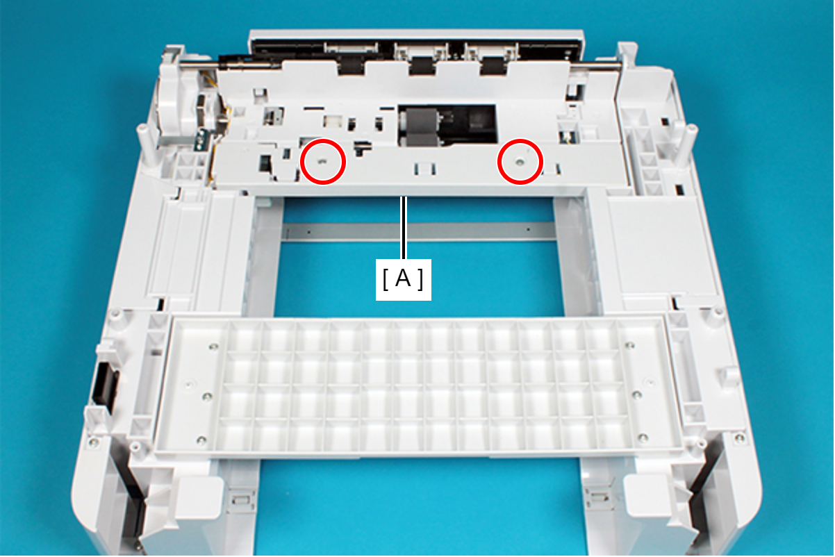
- : C.B.P-TITE-SCREW-3x10-F.ZN-3C
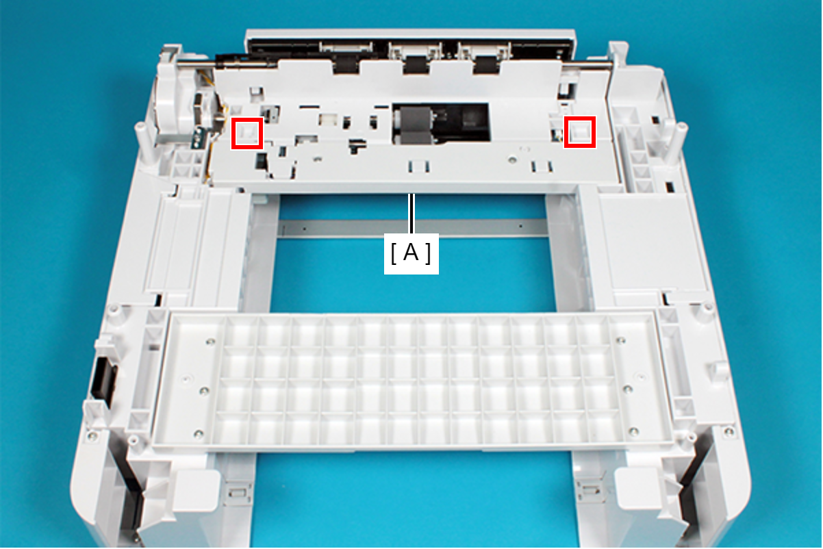
Assembly / 組み立てWhen installing the Middle Frame (A), attach the two dowels of the frame to the two positioning holes of the Middle Frame (A).
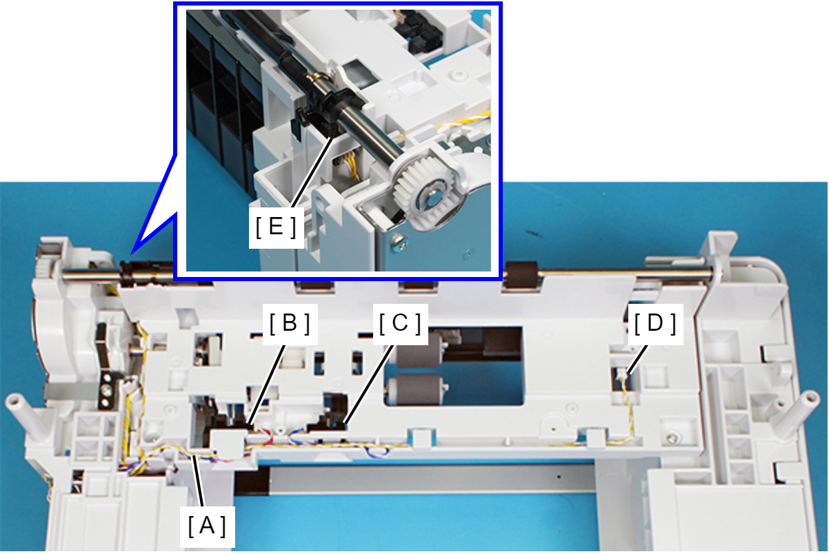
- Disconnect the Sensor Cable (A) from the connector of the following sensors.
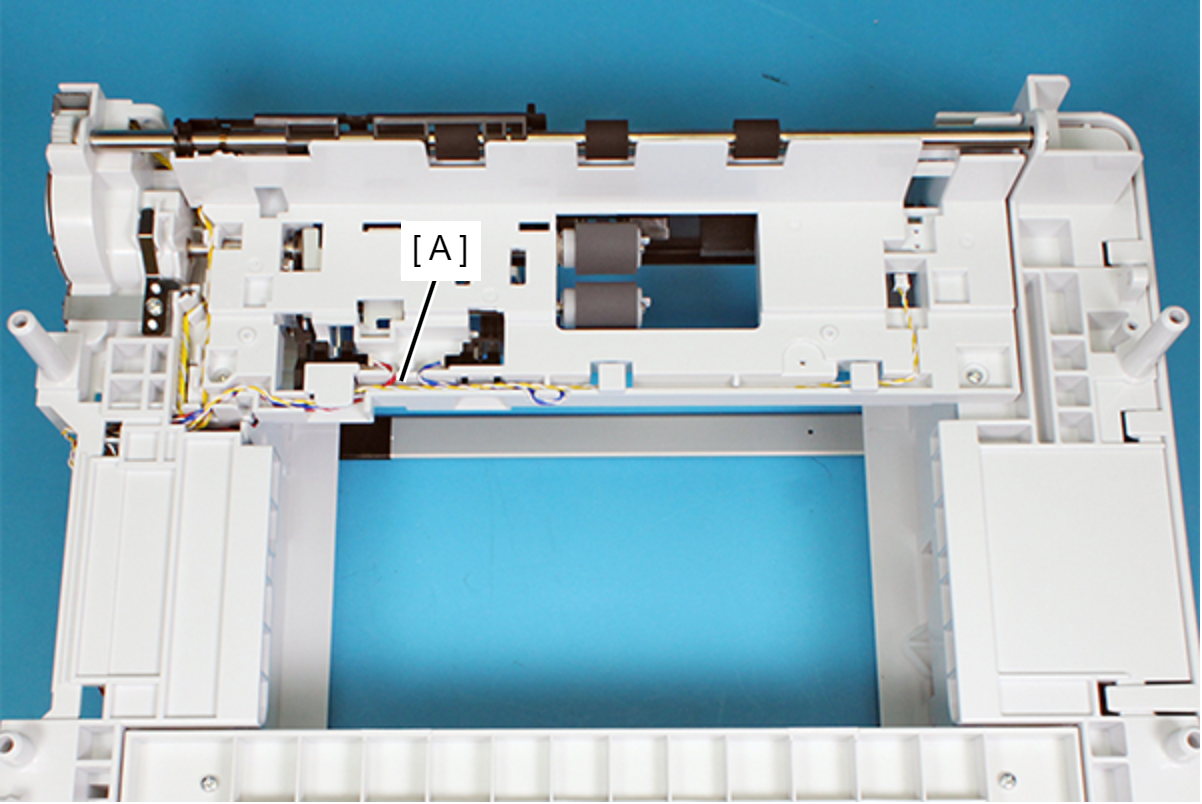
- Release the Sensor Cable (A) from the groove on the Rear Frame.
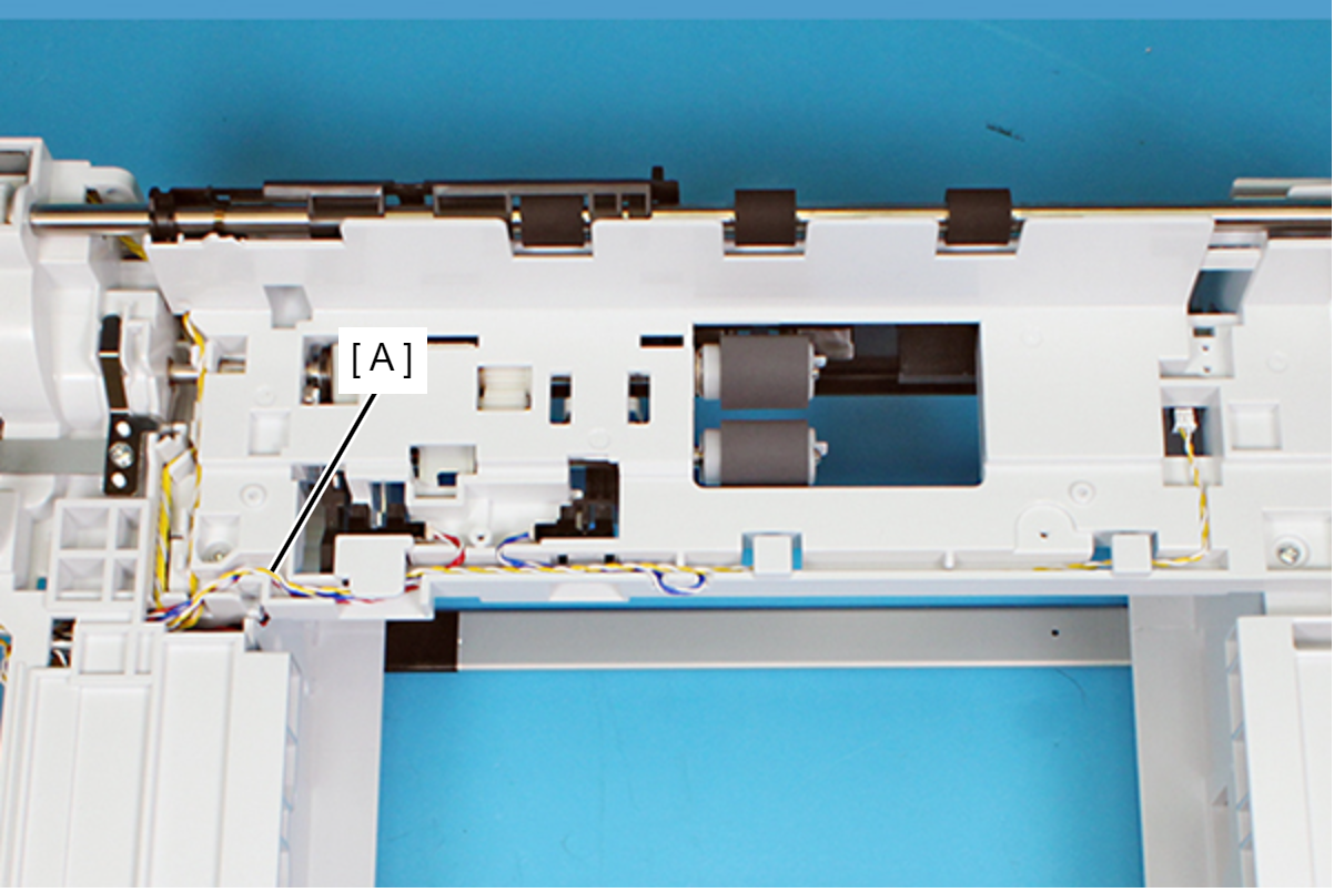
 Assembly / 組み立て
Route the Sensor Cable (A) through the groove on the Rear Frame, notch, and hook referring to the figure shown below.
- Disconnect the Sensor Cable (B) from the connector of the Optional Paper Cassette Main Board Assy (A) (CN7).
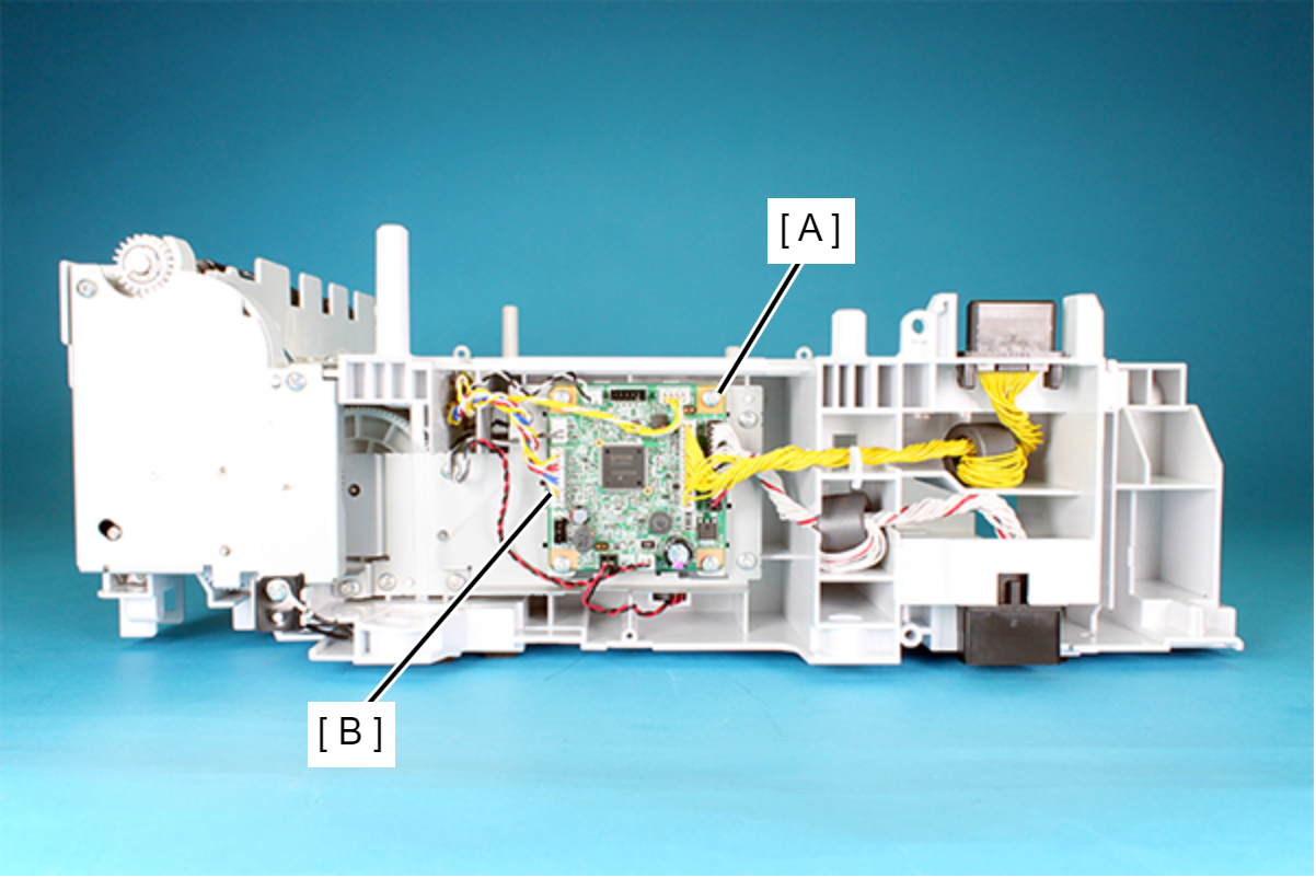
- Pull out and remove the Sensor Cable (A) from the hole on the frame.