
Seal Joint Head (WF-C529R Series)
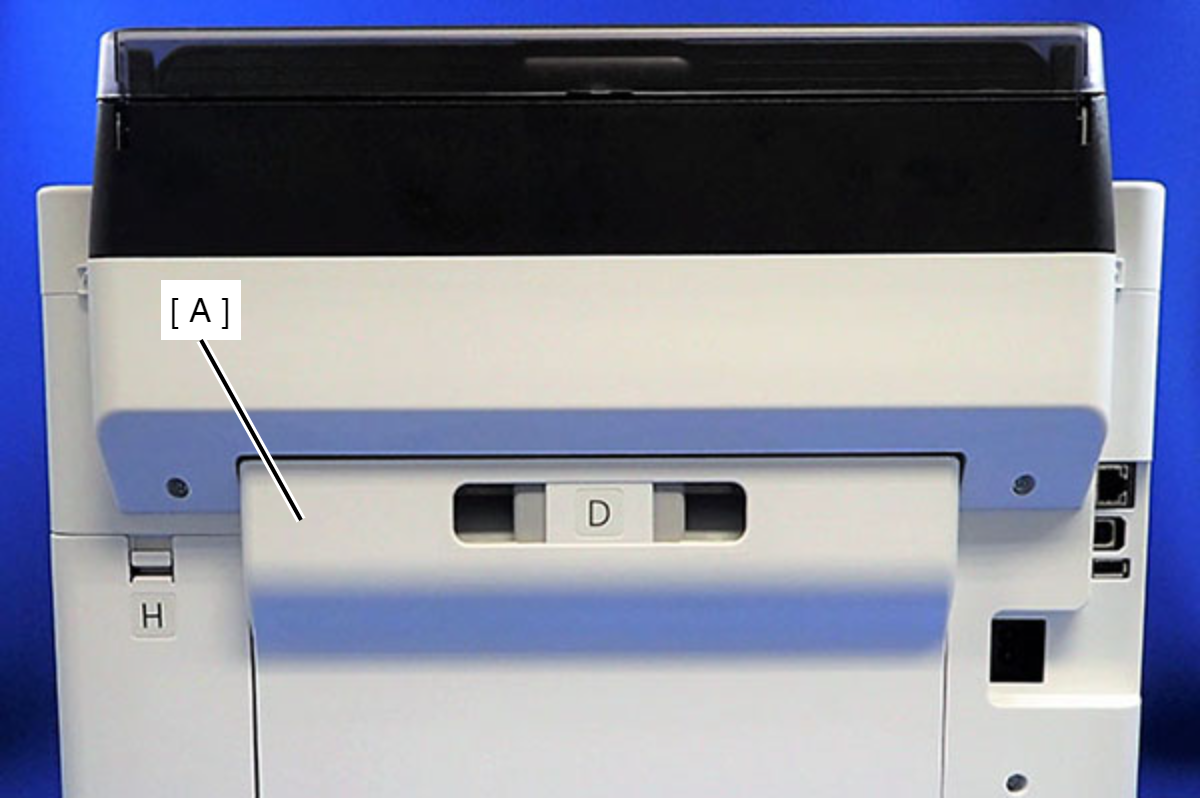
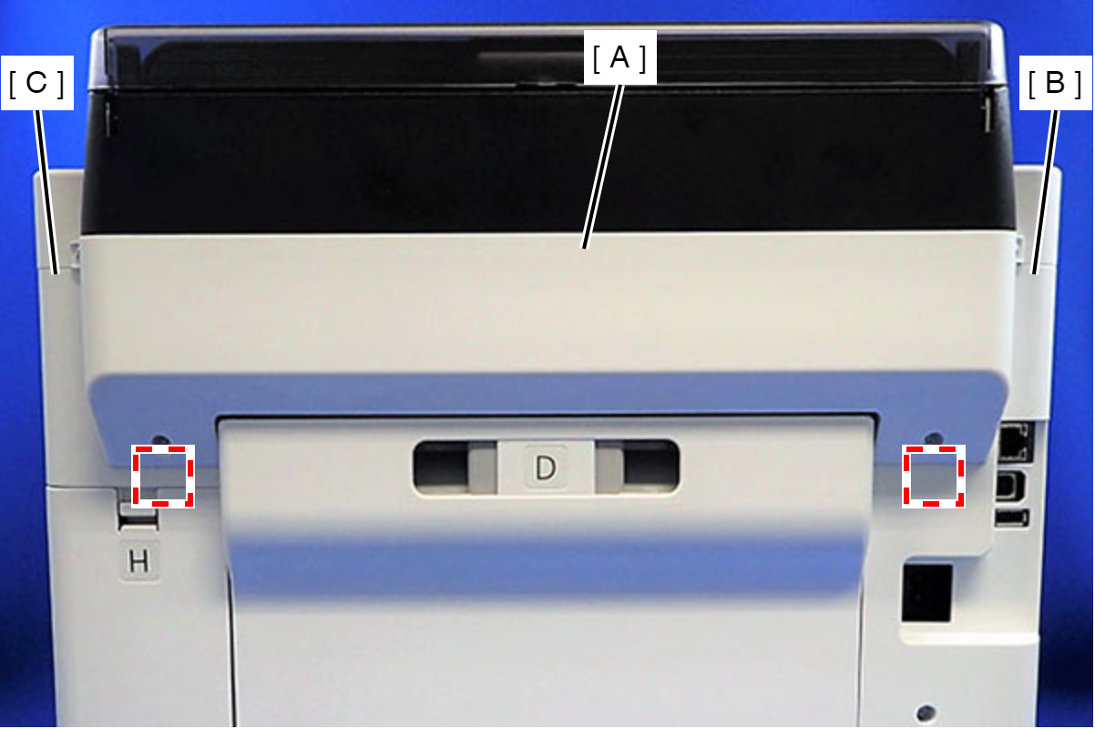
- Remove the Rear Unit (A).
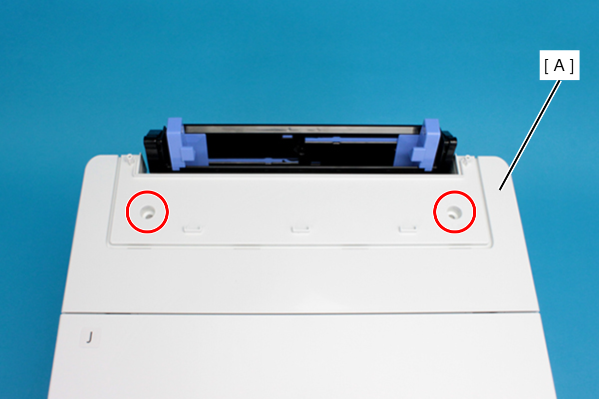
- Remove the two screws that secure the ASF Cover Assy (A).
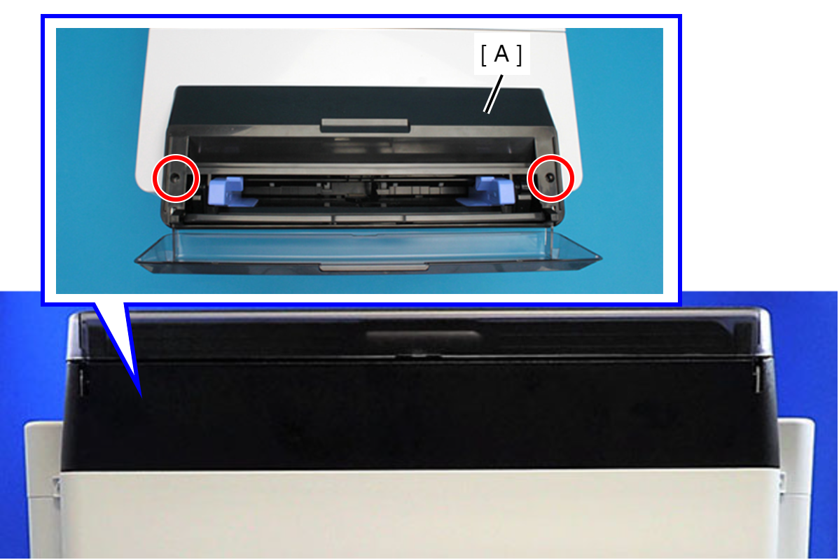
 : C.B.P-TITE-SCREW-3x10-F.ZN-3C
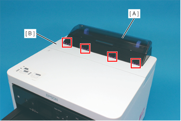
- Remove the four screws that secure the Rear Back Cover (A).
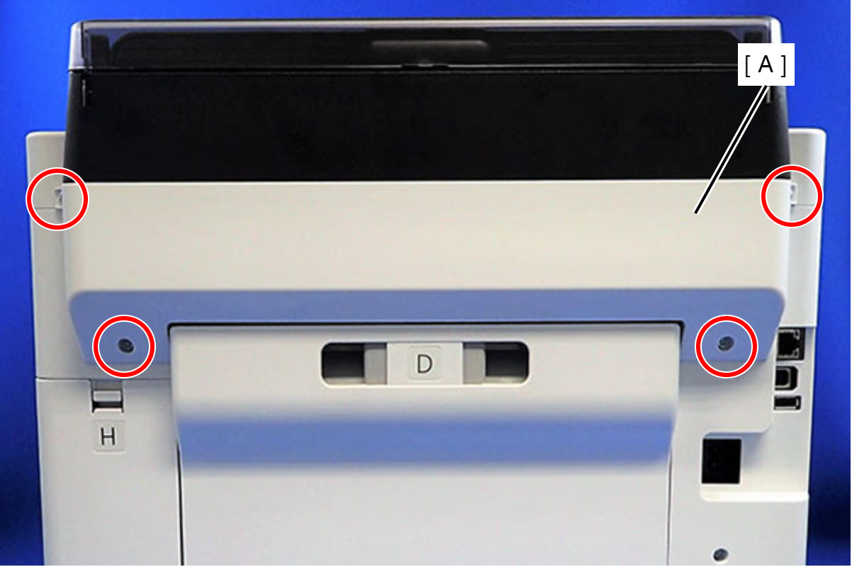
 : C.B.P-TITE-SCREW-3x10-F.ZN-3C
- Remove the Rear Back Cover (A) downward.
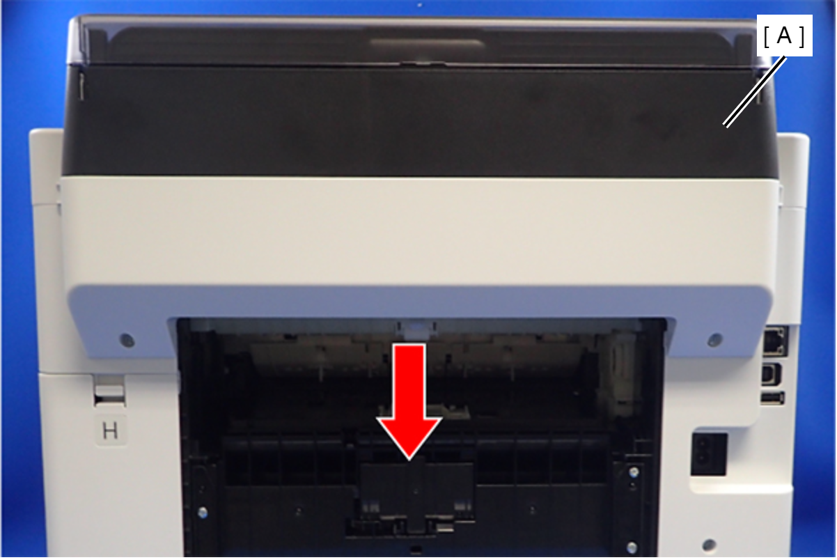
 Assembly / 組み立て
Attach the two dowels of the Rear Back Cover (A) to the positioning holes on the Housing Left (B) and the Housing Right (C).
- Remove the ASF Cover Assy (A) in the direction of the arrow.
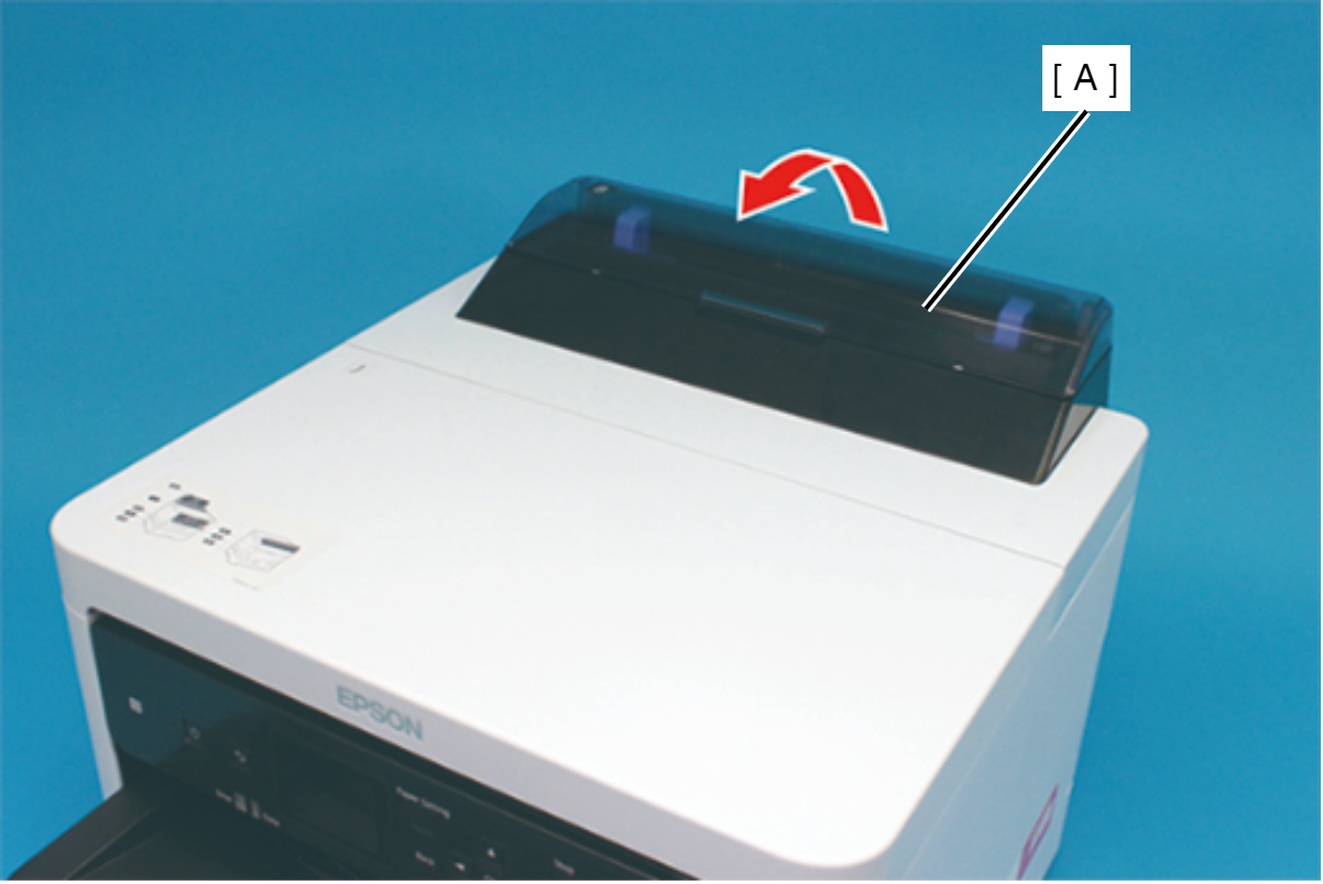
Assembly / 組み立てInsert the four tabs of the ASF Cover Assy (A) to the positioning holes of the Front Cover Retainer Plate.
- Remove the two screws securing the Front Cover Retainer Plate (A).
- : C.B.P-TITE-SCREW-3x10-F/ZN-3C
- Open the Printer Cover (A) and remove the four screws, and then remove the Front Cover Retainer Plate (B).
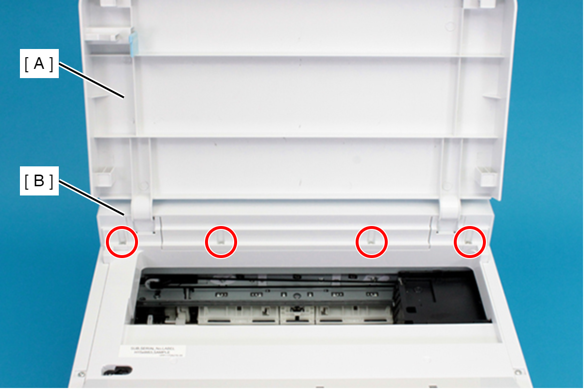
- : C.B.P-TITE-SCREW-3x10-F/ZN-3C
- Remove the Front Cover (A) upward.
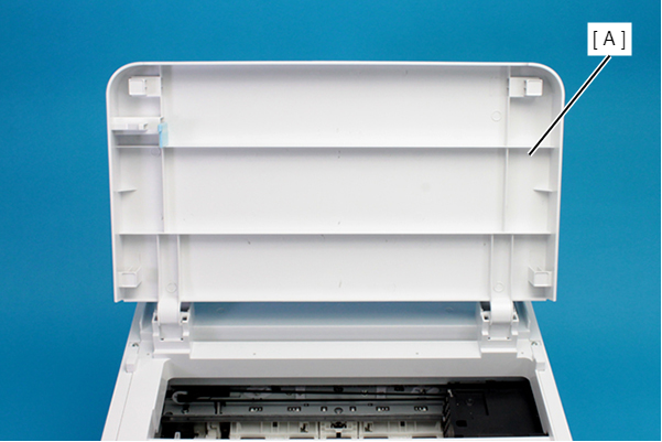
- Disengage the hook, and remove the Maintenance Box Cover (A).
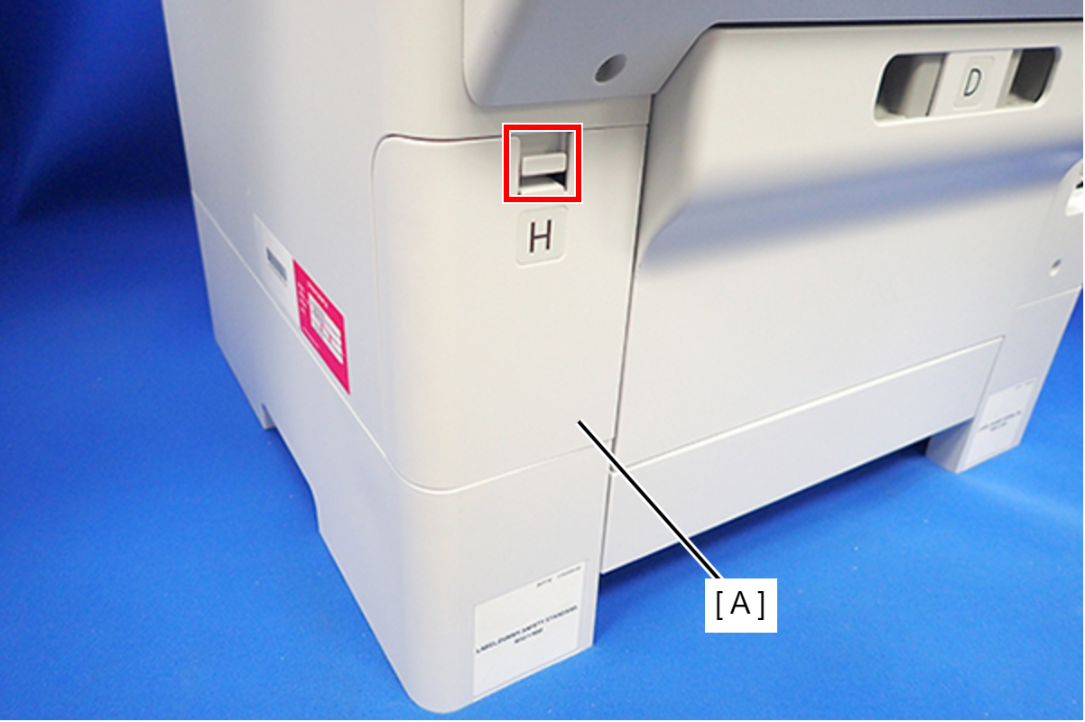
- Remove the three screws that secure the Housing Right (A).
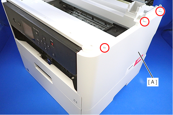
- : C.B.P-TITE-SCREW-3x10-F.ZN-3C
- Remove the two screws that secure the Housing Right (A).
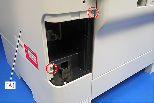
- : C.B.P-TITE-SCREW-3x10-F.ZN-3C
- Lift the Housing Right (A) to release the two hooks on the front side of the Housing Right (A), then remove the Housing Right (A).
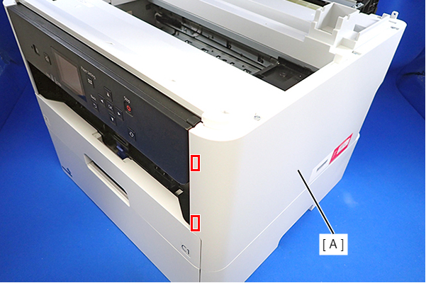 Assembly / 組み立て
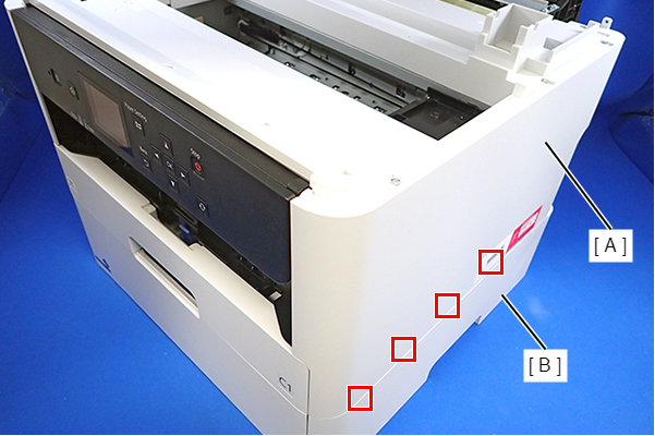
Insert the four tabs of the Housing Right (A) to the positioning holes on the Ink Supply Unit (B).
- Remove the three screws that secure the Housing Left (A).
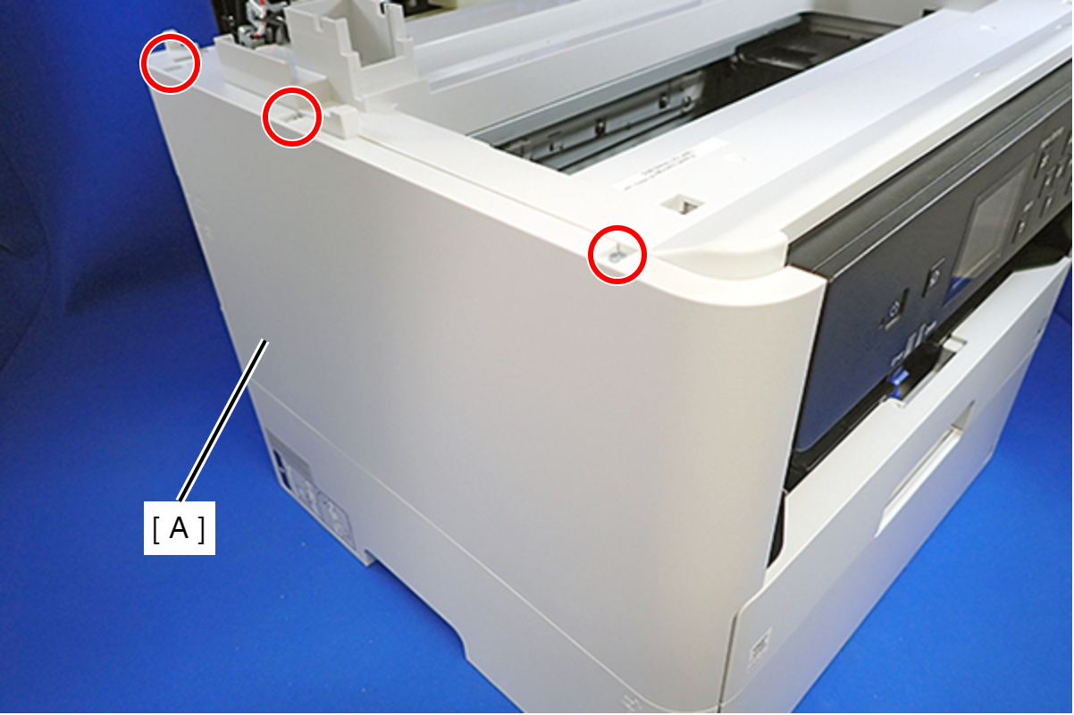
- : C.B.P-TITE-SCREW-3x10-F.ZN-3C
- Remove the two screws that secure the Housing Left (A).
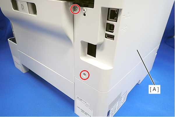
- : C.B.P-TITE-SCREW-3x10-F.ZN-3C
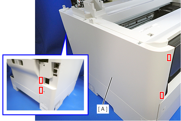
- Lift the Housing Left (A) to release the two hooks each on the front side and rear side of the Housing Left (A), and then remove the Housing Left (A).
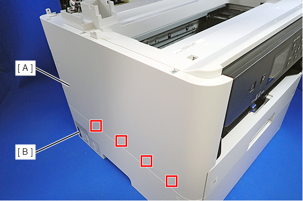
 Assembly / 組み立て
Insert the four tabs on the Housing Left (A) to the positioning holes of the Ink Supply Unit (B).
- Remove the six screws, then remove the Housing Upper (A).
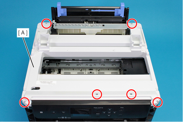
- : C.B.P-TITE-SCREW-3x10-F.ZN-3C
- Remove the two screws, and then remove the Head Upper Cover (A).
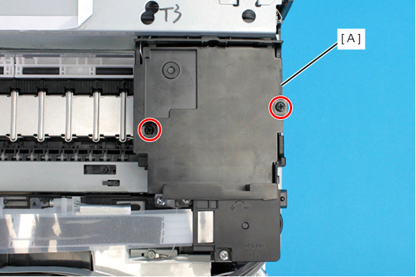
- : C.B.P-TITE-SCREW-3x10-F.ZB-3C
Assembly / 組み立てAttach the two tabs on the Head Upper Cover to the positioning holes of the CR Unit.
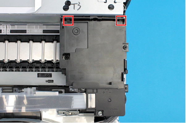
- Remove the two screws, and remove the Ink Tube Joint Cover (A).
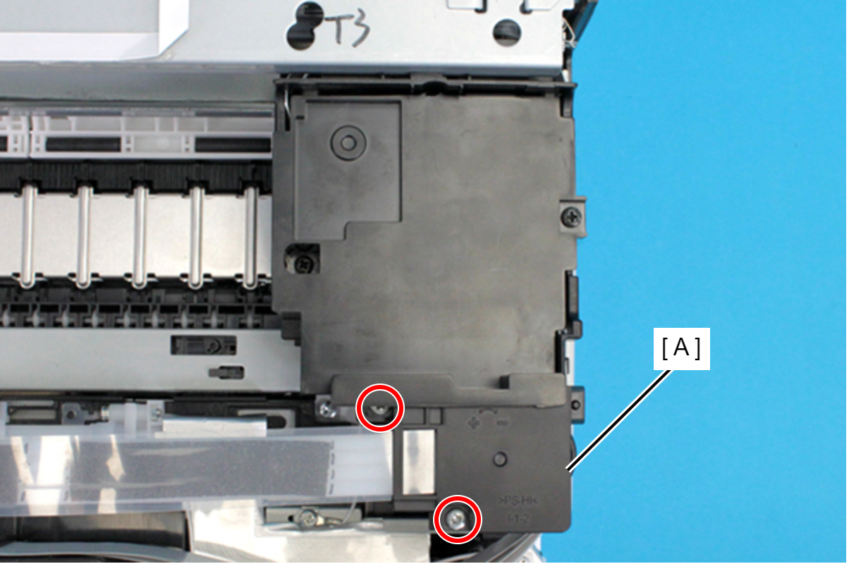
- : C.B.P-TITE-SCREW-3x10-F.ZN-3C
- Remove the film (A) from the hook on the Ink Tube Joint Cover.
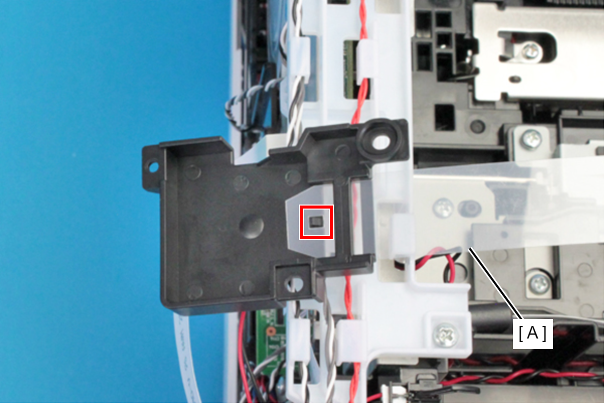 Assembly / 組み立て
Set the film (A) under the rib of the Ink Tube Joint Cover.
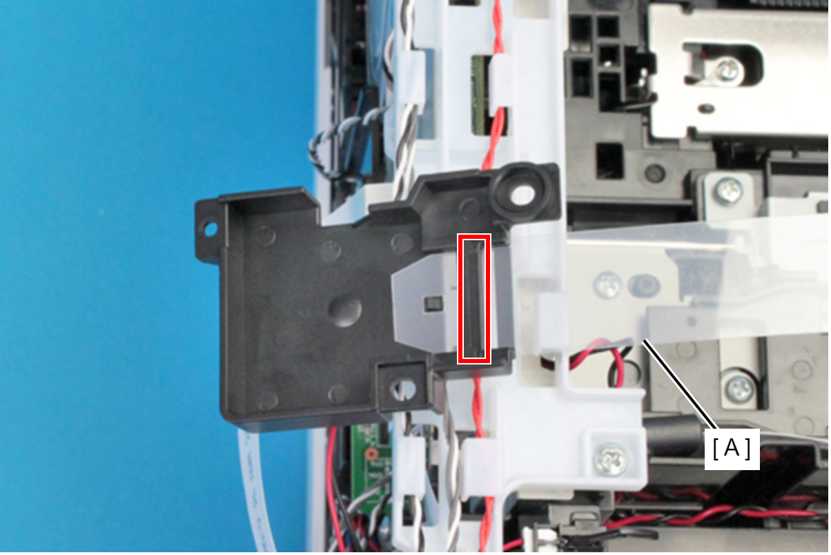
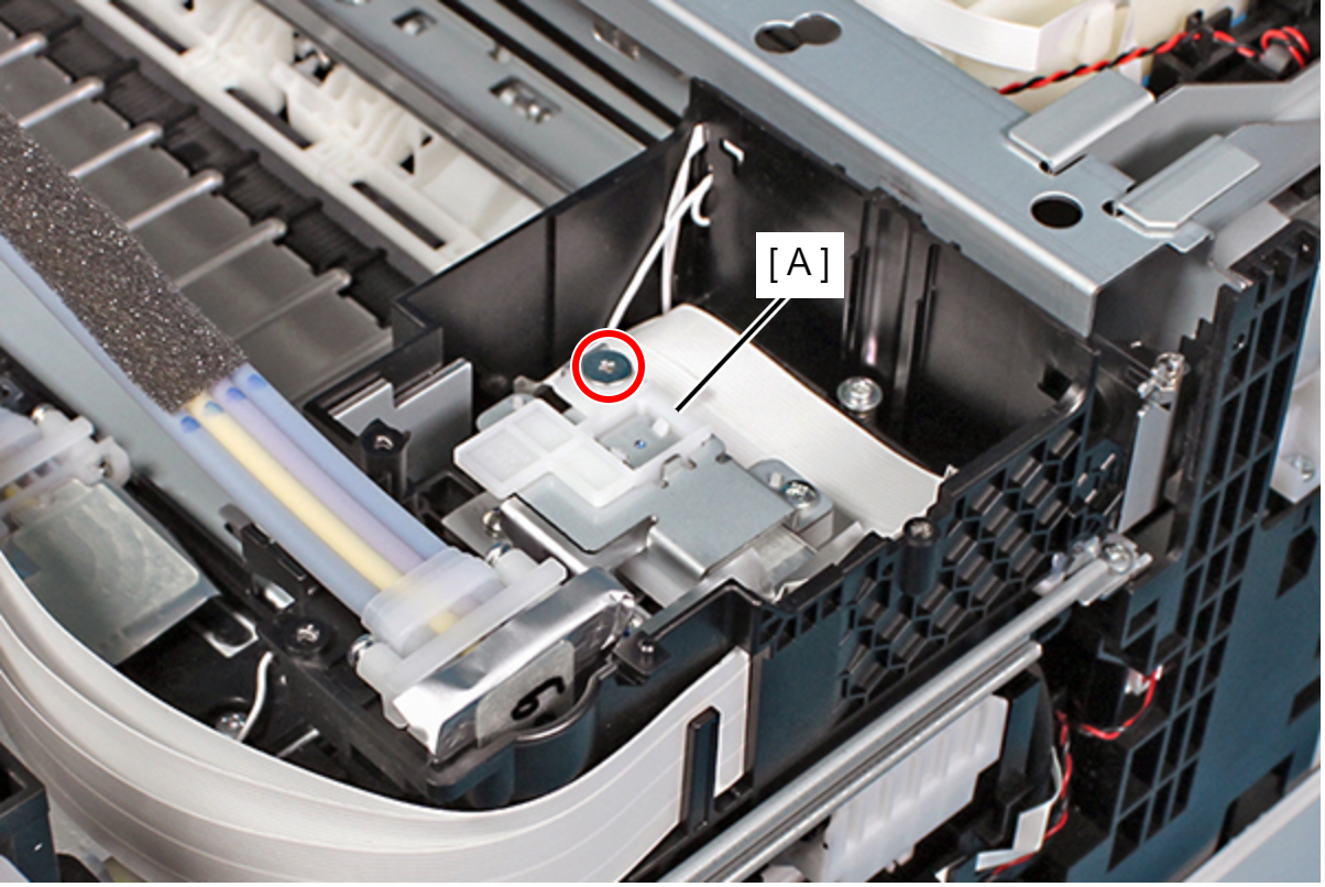
- Remove the screw, then remove the Magnetic Valve Assy (A).
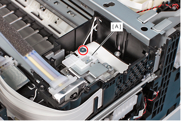
- : SCREW, JOINT, HEAD
Assembly / 組み立てMake sure the Magnetic Valve Assy is secured with the screw.
- Remove the two screws, and remove the Ink Supply Tube (A) from the Printhead.
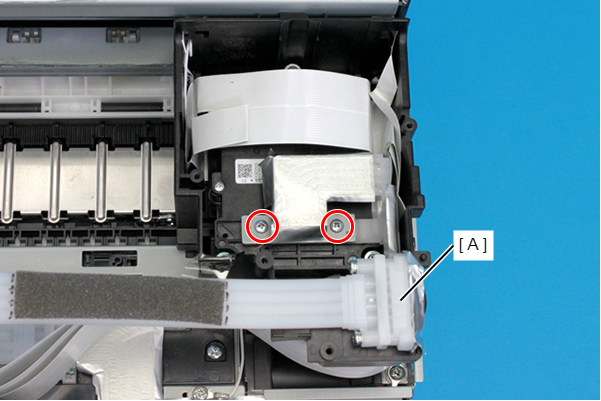
- : C.B.EP-TITE SCREW,2.6X17(B=14),F/ZN-3C
 Caution / 注意
As ink may adhere in this and following steps, prepare a waste cloth or the like in advance.
Assembly / 組み立て- When attaching the Plate (A), make sure to align the dowels on the Ink Supply Tube Assy (B) with the positioning holes on the Plate (A).
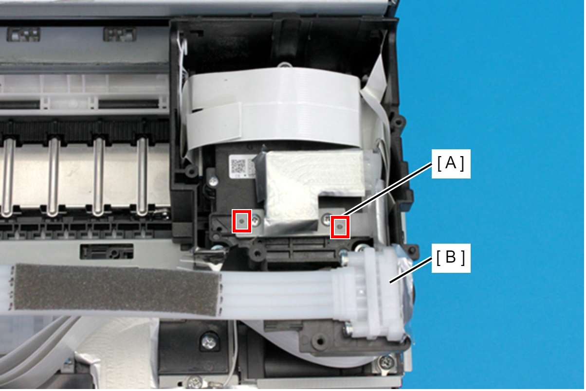
- The screws that secure the Plate (C.B.EP-TITE SCREW,2.6X17(B=14),F/ZN-3C) are supplied as ASP.
Remove the Seal Joint Head (C) between the Ink Supply Tube Assy (A) and Printhead (B).
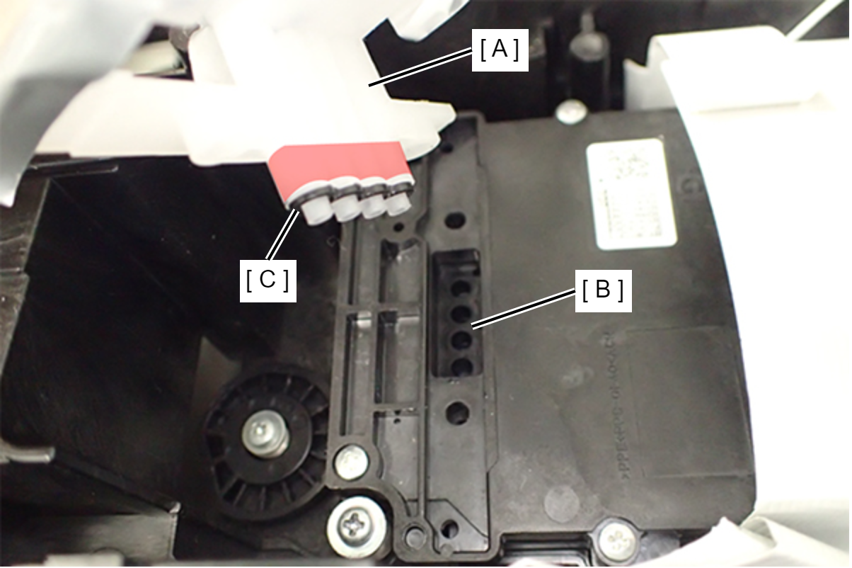 Assembly / 組み立て
- If ink is remained to ink tube joint part (A) of Ink Supply Unit, Ink Leak Check can not perform correctly. Therefore cleaning the ink surely.
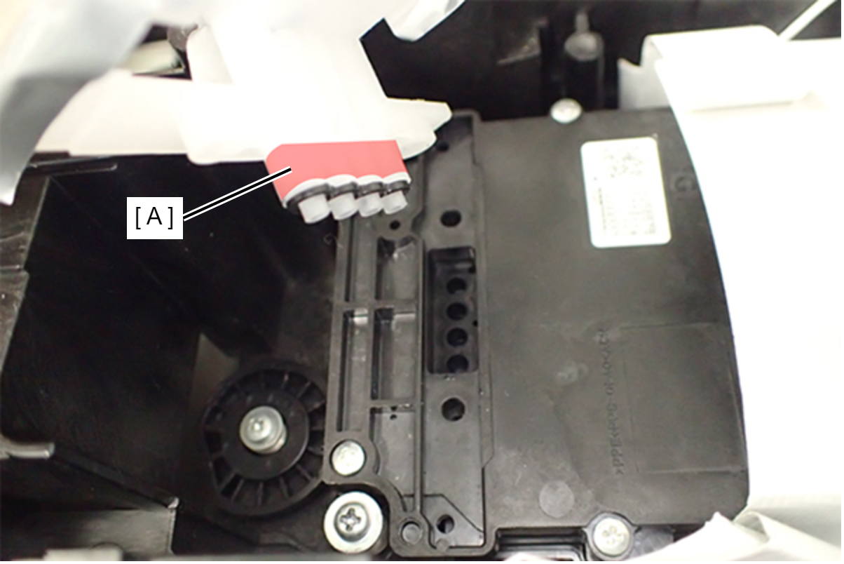
- Take care regarding the following points with the Seal Joint Head (A).
- When replacing the Printhead, replace the seal joint head with the new one because it cannot be reused.
- Check the Seal Joint Head (A) is not double-installed.
- Check the Seal Joint Head (A) is inserted all the way.
- Check that foreign object does not adhere on the Seal Joint Head (A).
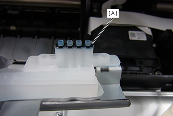
- If ink is remained to ink tube joint part (A) of Ink Supply Unit, Ink Leak Check can not perform correctly. Therefore cleaning the ink surely.