
Ink Supply Tube Assy (WF-C529R Series)
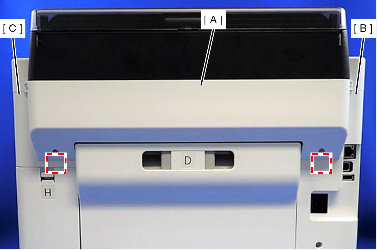
- Remove the Rear Unit (A).
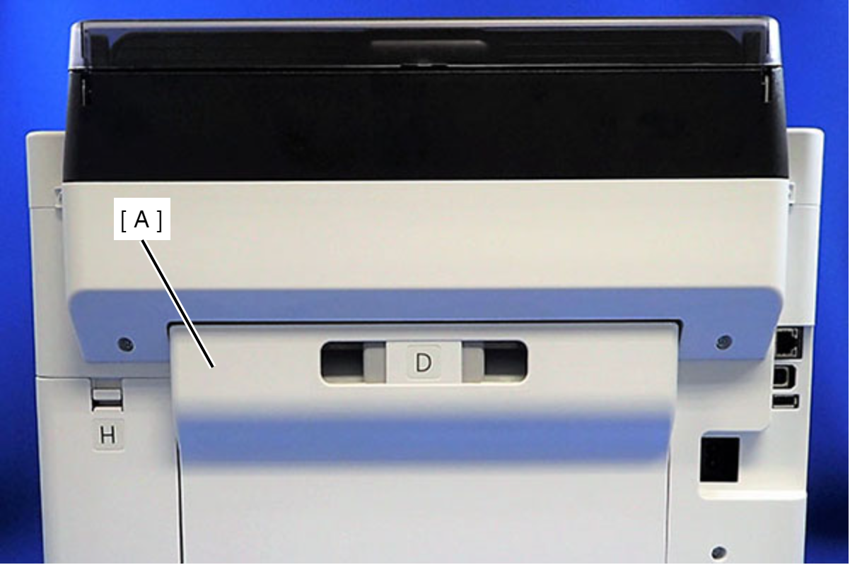
- Remove the two screws that secure the ASF Cover Assy (A).
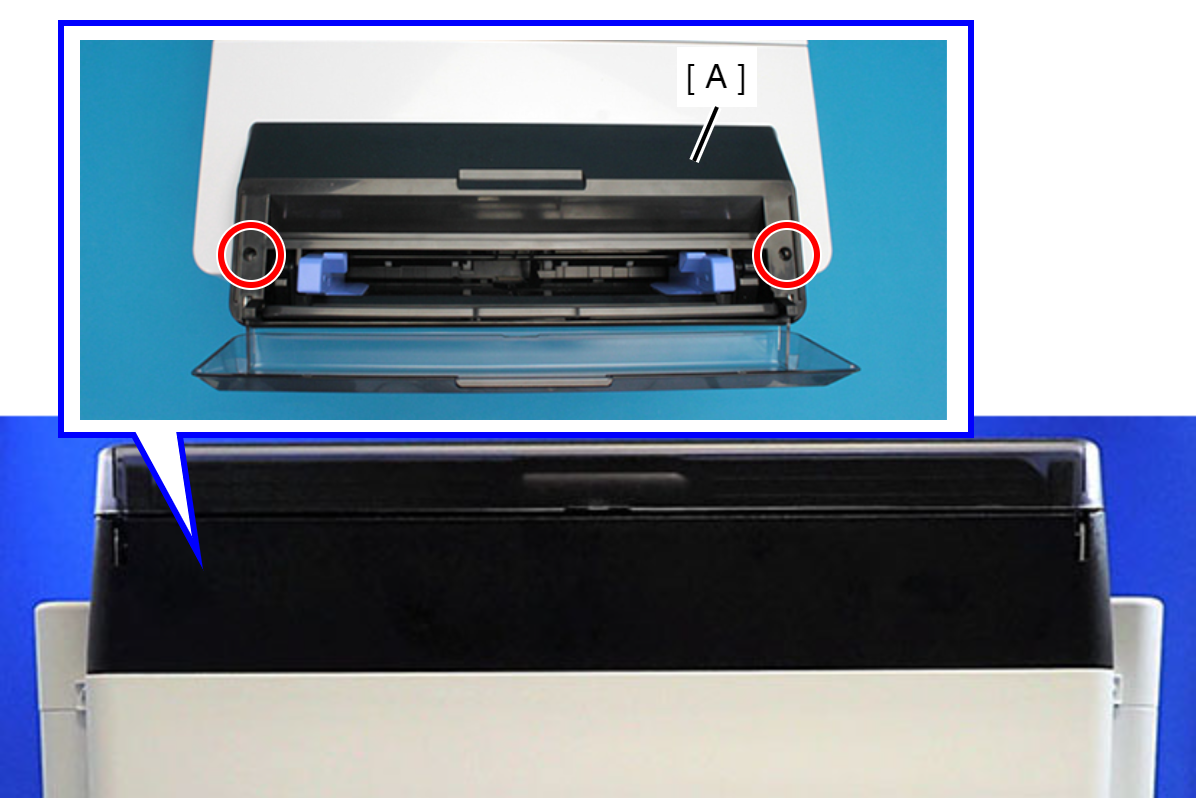
 : C.B.P-TITE-SCREW-3x10-F.ZN-3C
- Remove the four screws that secure the Rear Back Cover (A).
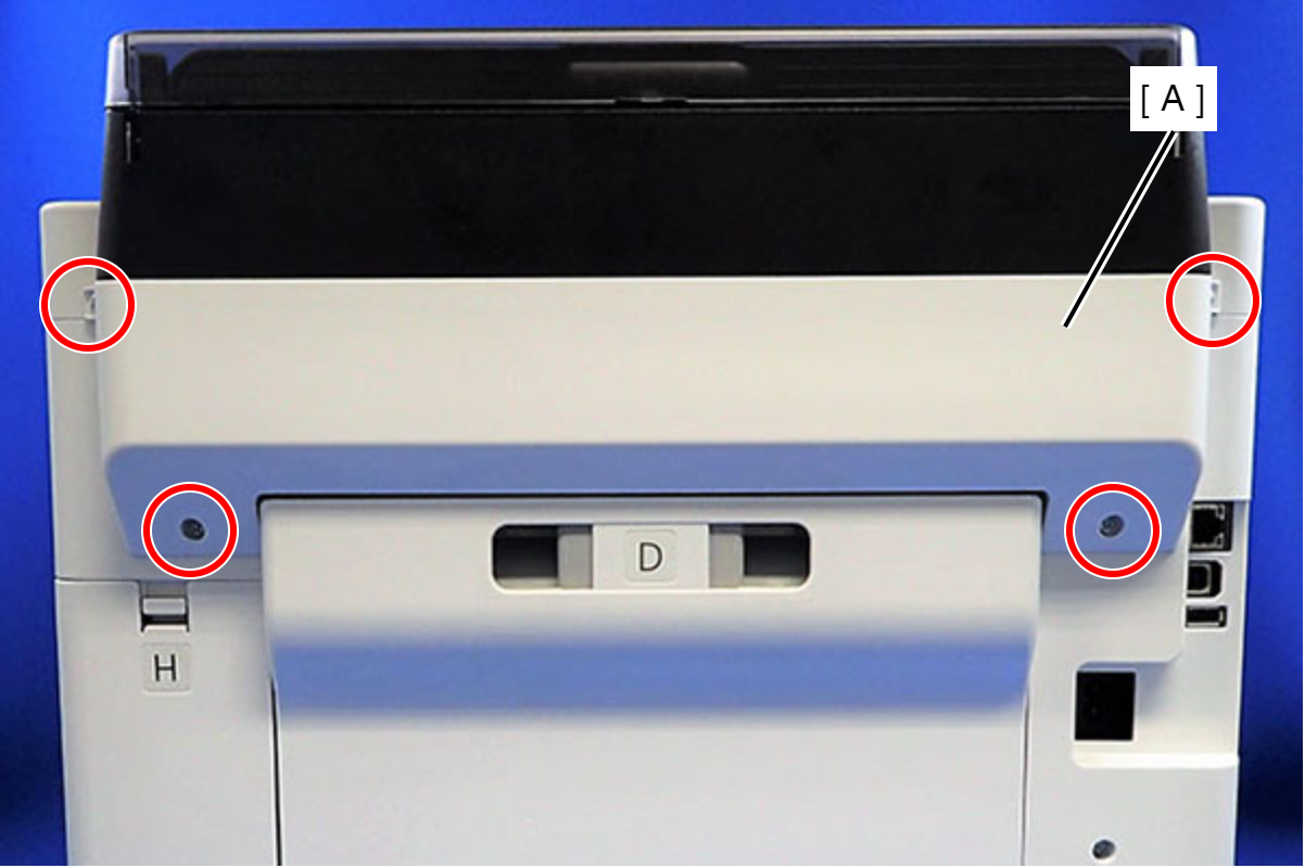
 : C.B.P-TITE-SCREW-3x10-F.ZN-3C
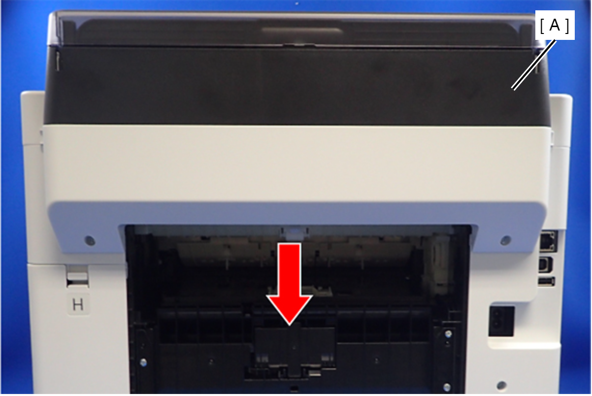
- Remove the Rear Back Cover (A) downward.
 Assembly / 組み立て
Attach the two dowels of the Rear Back Cover (A) to the positioning holes on the Housing Left (B) and the Housing Right (C).
- Remove the ASF Cover Assy (A) in the direction of the arrow.
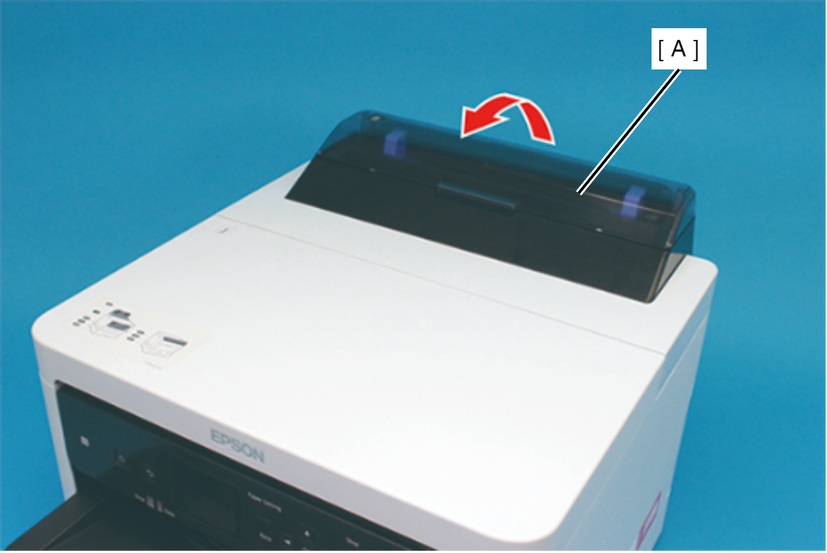
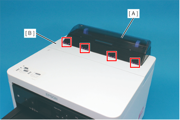
Assembly / 組み立てInsert the four tabs of the ASF Cover Assy (A) to the positioning holes of the Front Cover Retainer Plate.
- Remove the two screws securing the Front Cover Retainer Plate (A).
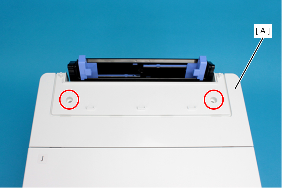
- : C.B.P-TITE-SCREW-3x10-F/ZN-3C
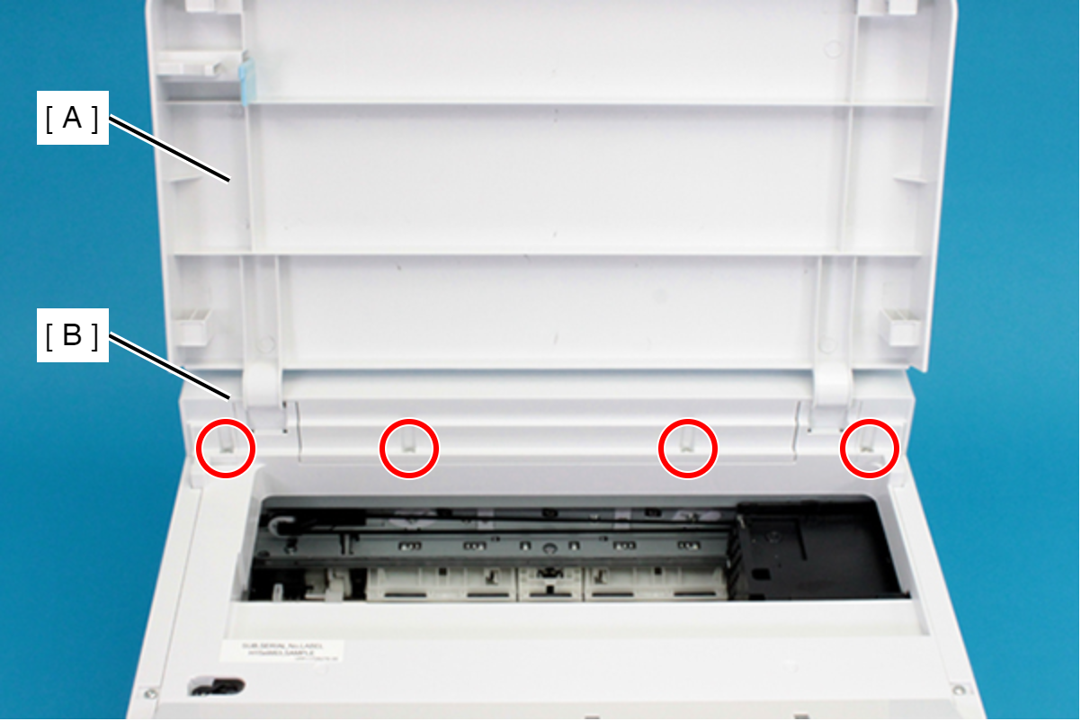
- Open the Printer Cover (A) and remove the four screws, and then remove the Front Cover Retainer Plate (B).
- : C.B.P-TITE-SCREW-3x10-F/ZN-3C
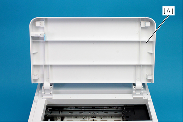
- Remove the Front Cover (A) upward.
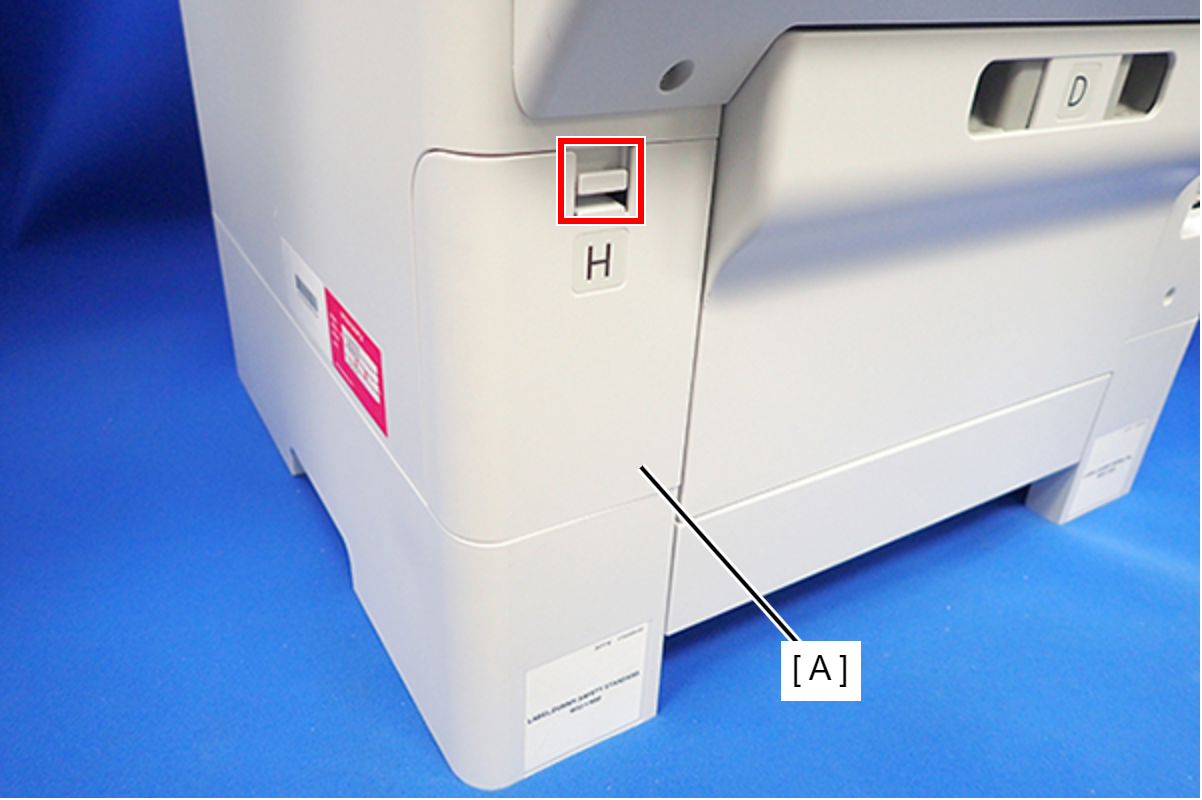
- Disengage the hook, and remove the Maintenance Box Cover (A).
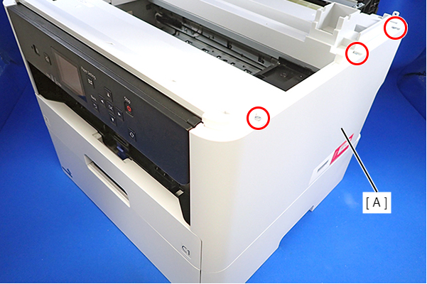
- Remove the three screws that secure the Housing Right (A).
- : C.B.P-TITE-SCREW-3x10-F.ZN-3C
- Remove the two screws that secure the Housing Right (A).
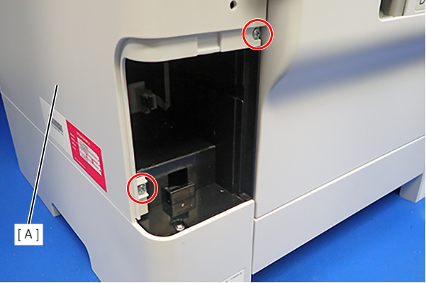
- : C.B.P-TITE-SCREW-3x10-F.ZN-3C
- Lift the Housing Right (A) to release the two hooks on the front side of the Housing Right (A), then remove the Housing Right (A).
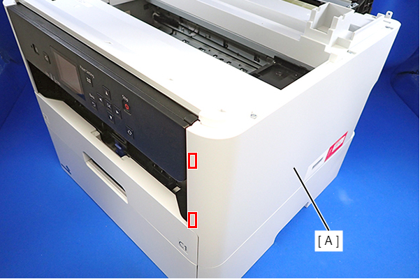 Assembly / 組み立て
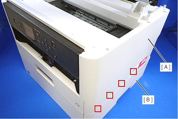
Insert the four tabs of the Housing Right (A) to the positioning holes on the Ink Supply Unit (B).
- Remove the three screws that secure the Housing Left (A).
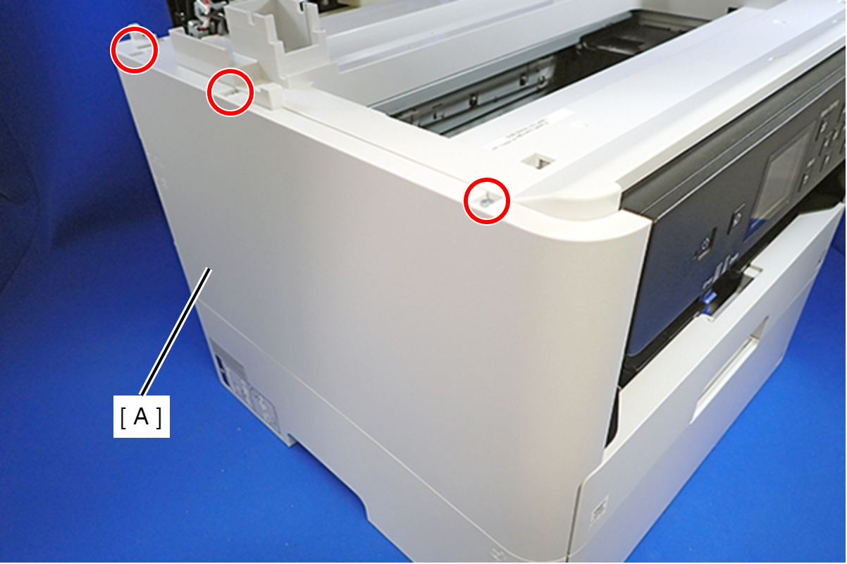
- : C.B.P-TITE-SCREW-3x10-F.ZN-3C
- Remove the two screws that secure the Housing Left (A).
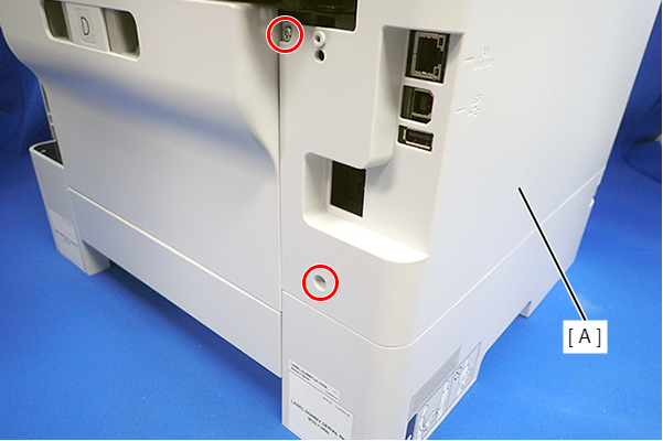
- : C.B.P-TITE-SCREW-3x10-F.ZN-3C
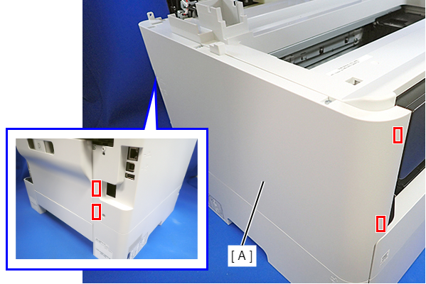
- Lift the Housing Left (A) to release the two hooks each on the front side and rear side of the Housing Left (A), and then remove the Housing Left (A).
 Assembly / 組み立て
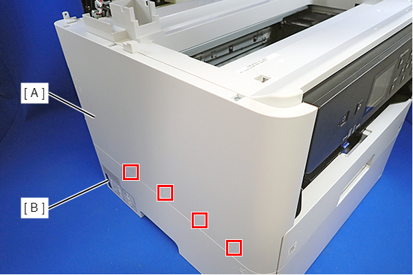
Insert the four tabs on the Housing Left (A) to the positioning holes of the Ink Supply Unit (B).
- Remove the six screws, then remove the Housing Upper (A).
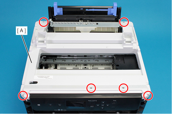
- : C.B.P-TITE-SCREW-3x10-F.ZN-3C
- Remove the two screws, and then remove the Head Upper Cover (A).
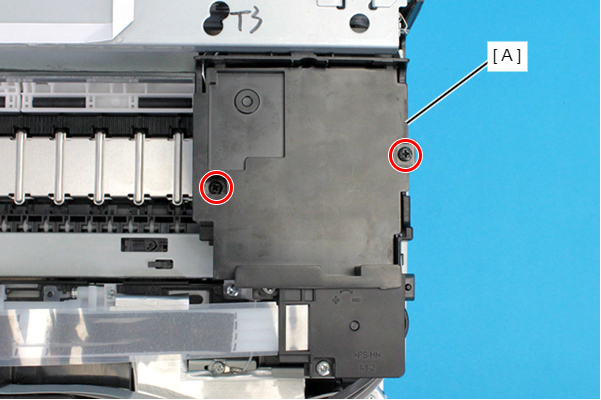
- : C.B.P-TITE-SCREW-3x10-F.ZB-3C
Assembly / 組み立てAttach the two tabs on the Head Upper Cover to the positioning holes of the CR Unit.
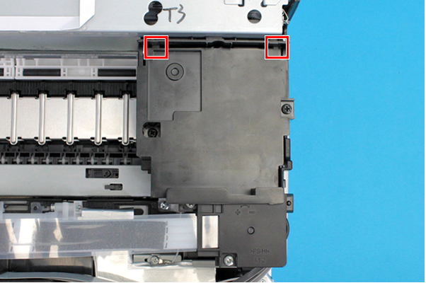
- Remove the two screws, and remove the Ink Tube Joint Cover (A).
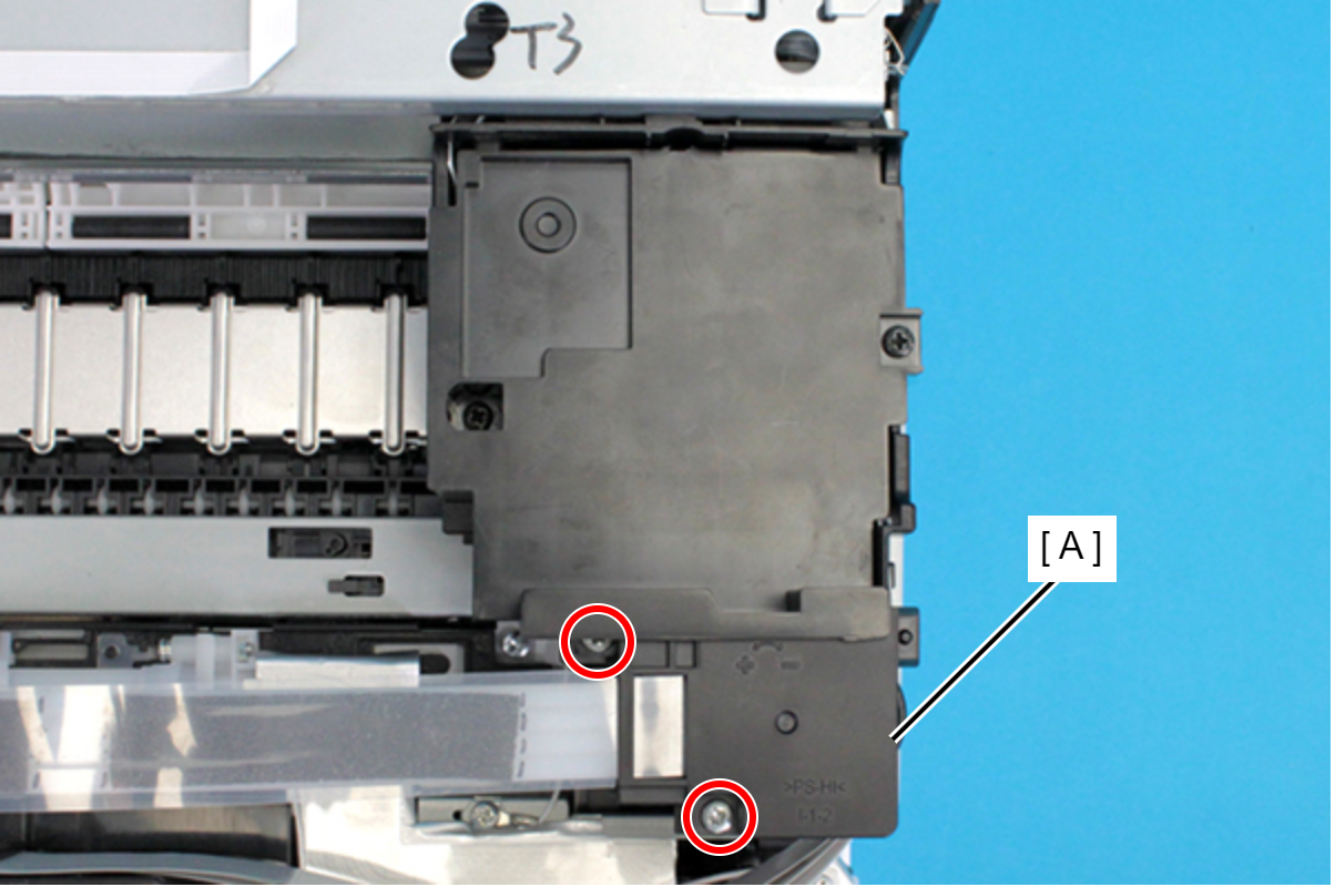
- : C.B.P-TITE-SCREW-3x10-F.ZN-3C
- Remove the film (A) from the hook on the Ink Tube Joint Cover.
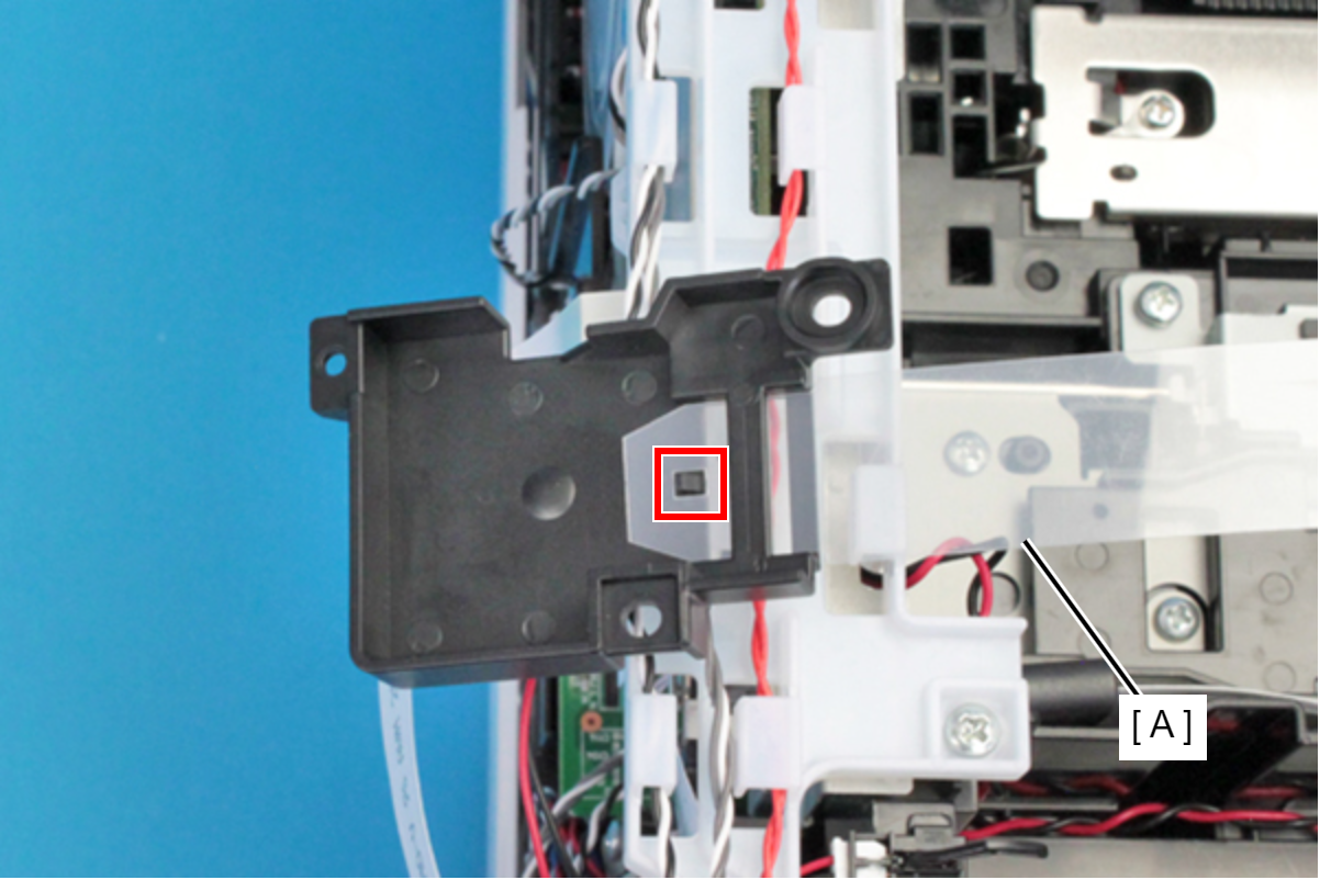 Assembly / 組み立て
Set the film (A) under the rib of the Ink Tube Joint Cover.
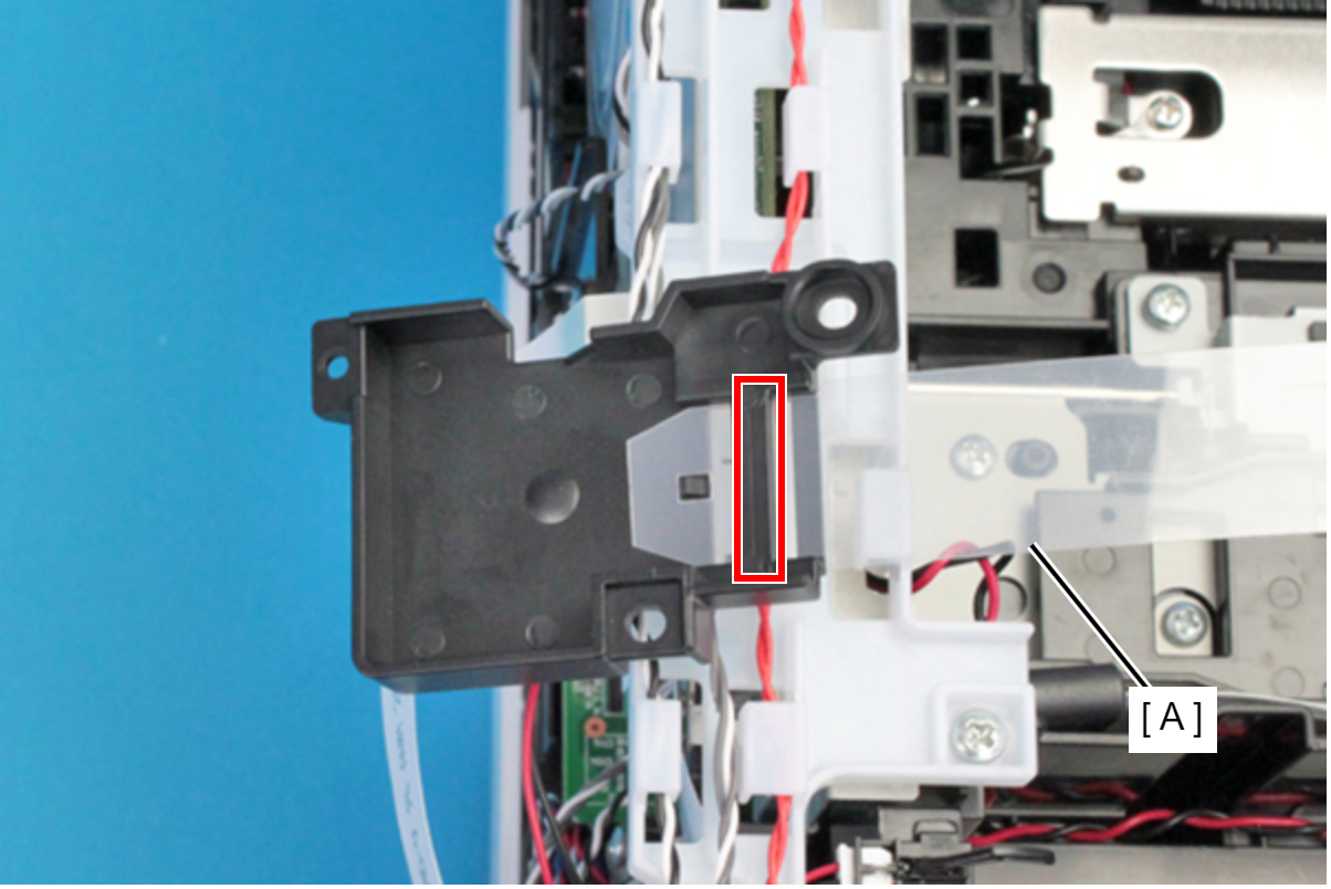
- Remove the screw, then remove the Magnetic Valve Assy (A).
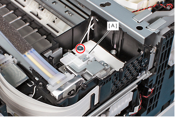
- : SCREW, JOINT, HEAD
Assembly / 組み立てMake sure the Magnetic Valve Assy is secured with the screw.
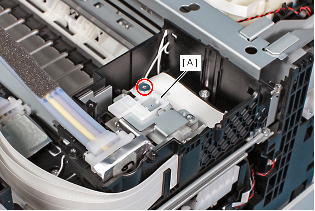
- Remove the screw, then remove the Magnetic Valve Assy B (A).
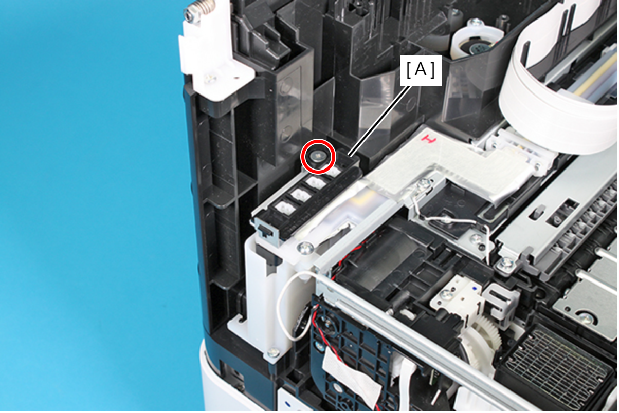
- : SCREW, JOINT, HEAD
Assembly / 組み立て- When attaching the Magnetic Valve Assy, B (A), make sure to align the rib with the hole on the plate.
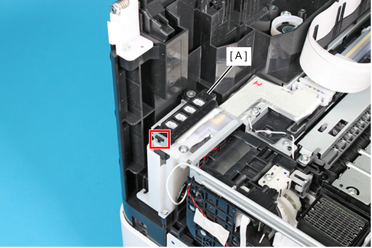
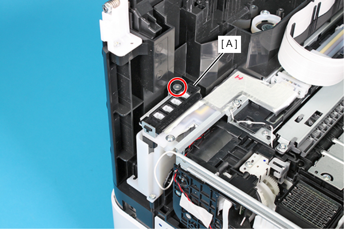
- Make sure the Magnetic Valve Assy, B (A) is secured with the screw.
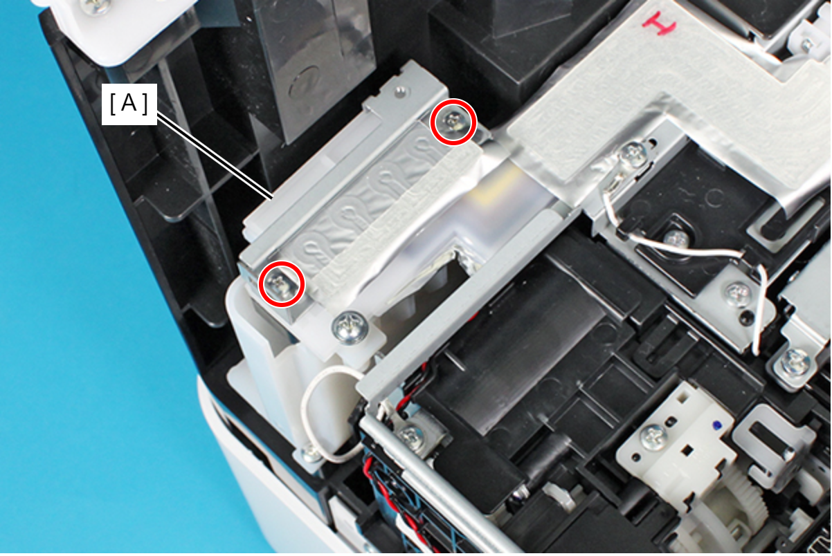
- Remove the two screws and then remove the plate (A).
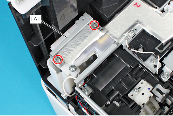
- : C.B.(S-P1)SCREW,2.5X18,F/ZN-3C
Assembly / 組み立て- When installing the Ink Supply Tube (A) to the Ink Supply Unit Assy, make sure to tighten the screws using a torque driver with the specified torque.
- Screw tightening torque: 0.25 ± 0.03N×m
- The S6 screw (A) and the Hexagon nut (H.N.-1,2.5,F/ZN-3C) is supplied as ASP.
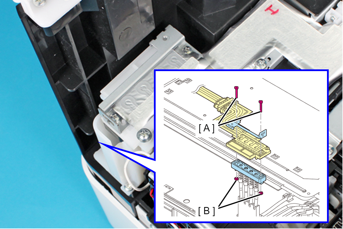
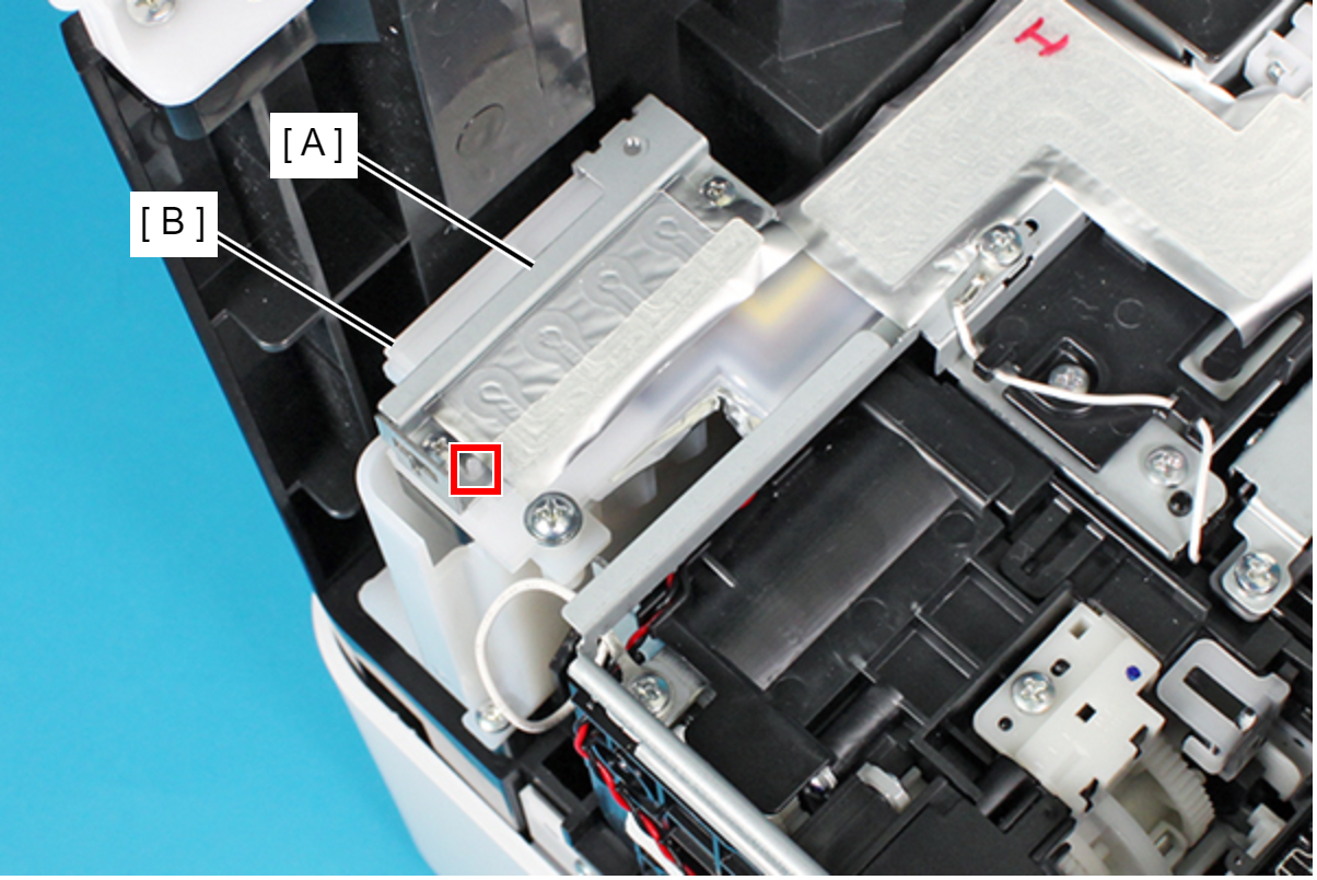
- When attaching the plate (A), make sure to align the dowel on the Ink Supply Tube Assy (B) and the positioning hole on the plate.
- Remove the two screws, and remove the Ink Supply Tube (B) from the Printhead (A).
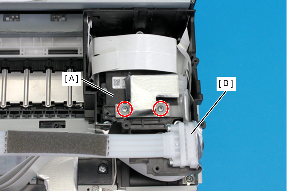
- : C.B.EP-TITE SCREW,2.6X17(B=14),F/ZN-3C
 Caution / 注意
As ink may adhere in this and following steps, prepare a waste cloth or the like in advance.
Assembly / 組み立てWhen attaching the Plate (A), make sure to align the dowels on the Ink Supply Tube Assy (B) with the positioning holes on the Plate.
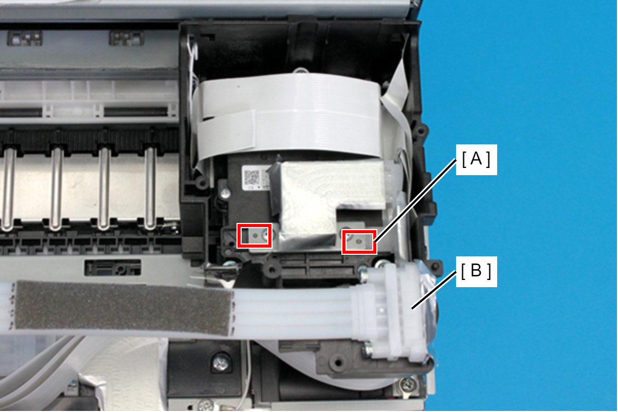
- The screws that secure the Plate (C.B.EP-TITE SCREW,2.6X17(B=14),F/ZN-3C) are supplied as ASP.
- Remove the Ink Tube Assy (B) from the Tube Clamp (A).
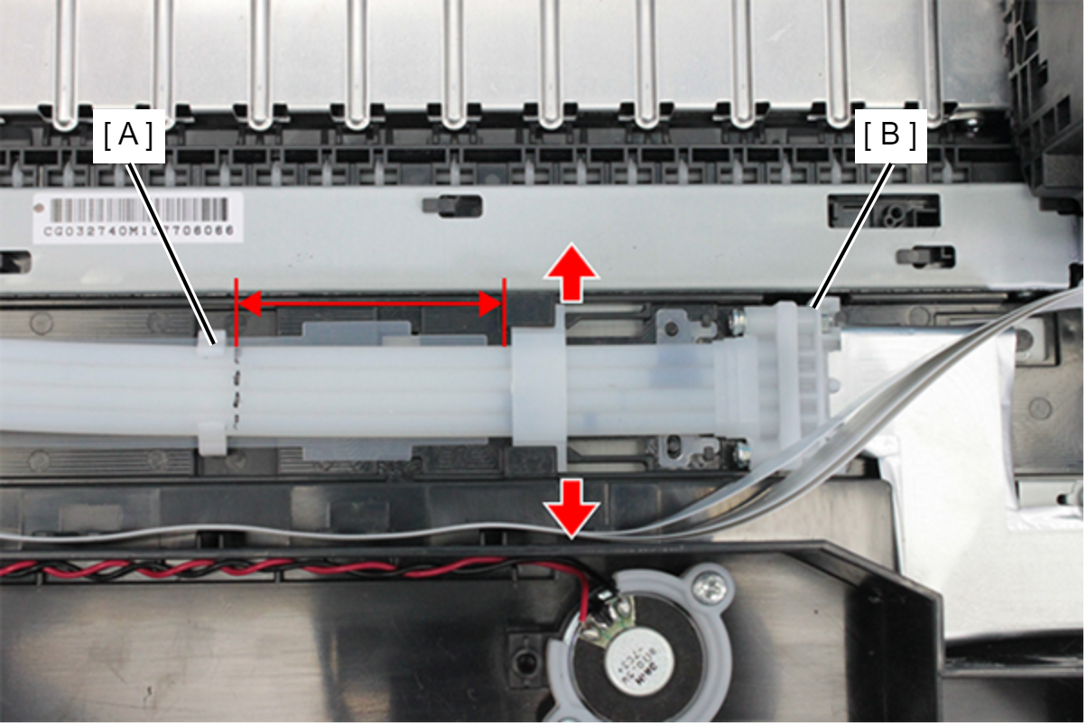 Assembly / 組み立て
At the marking point (B) on the Ink Supply Tube Assy (A), attach the Ink Supply Tube Assy (A) to the Tube Clamp (C). If the marking (B) is not visible, refer to the figure below.
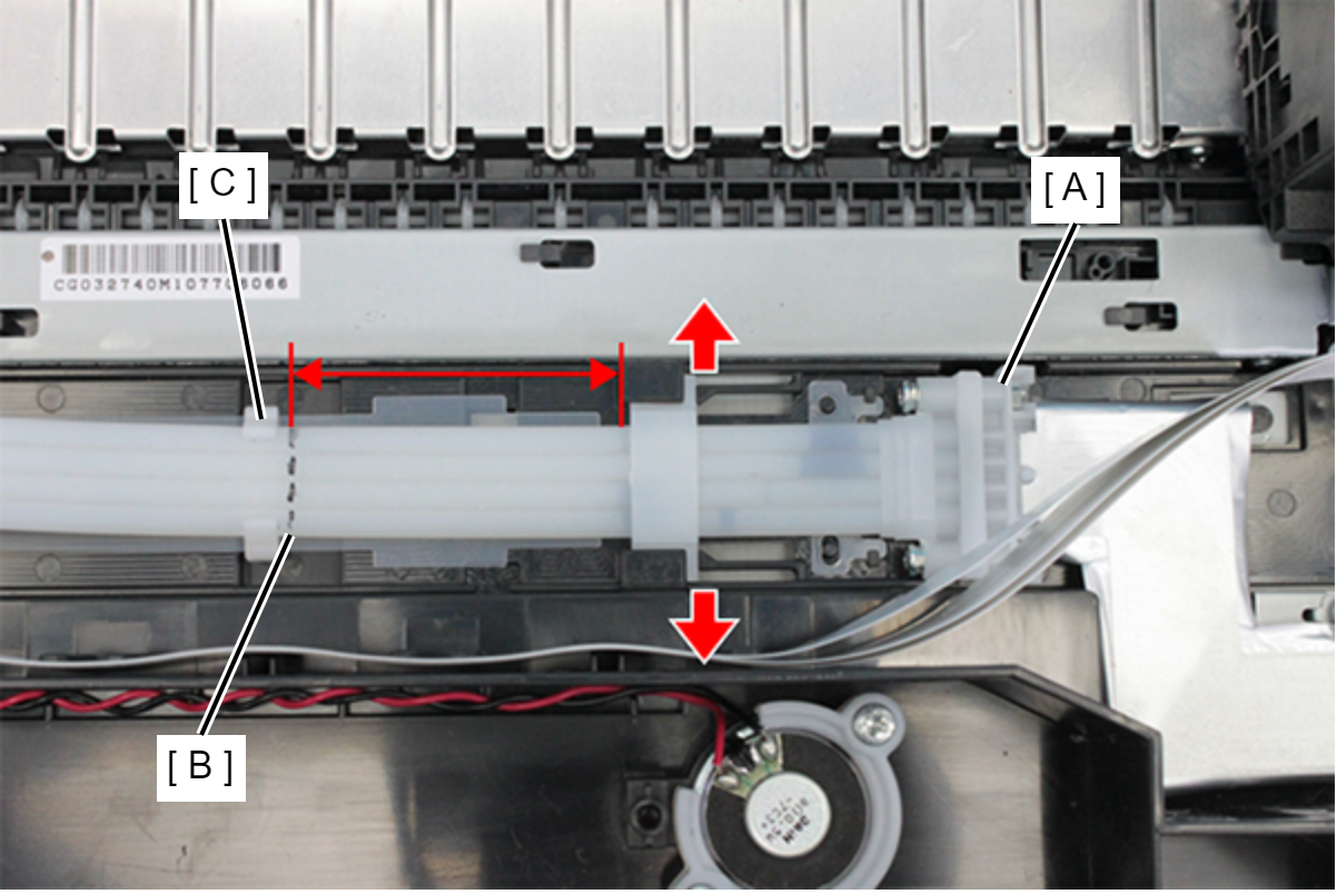
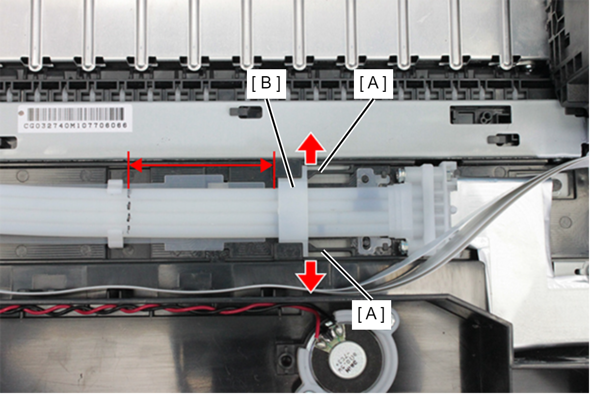
- Remove the Tube Holder (B) while pressing the two hooks (A) outward.
- Remove the screw.
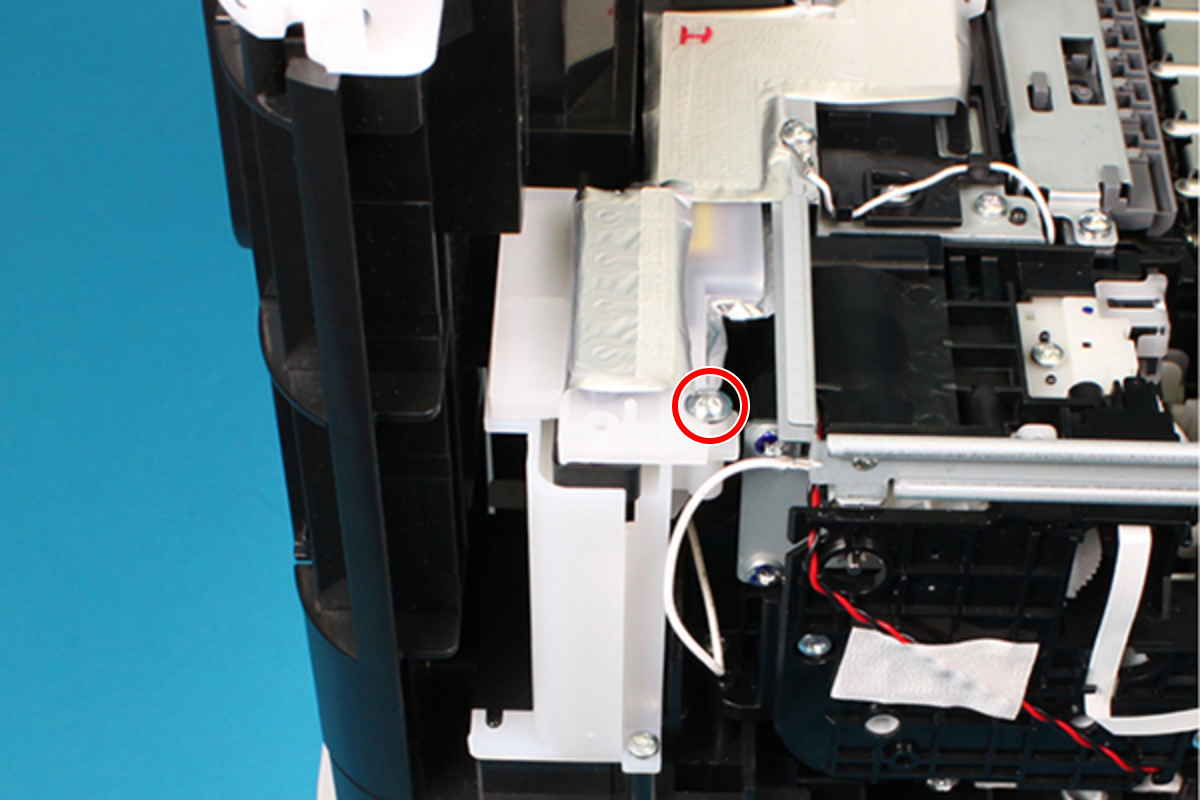
- : C.C.P-TITE-SCREW-3x12-F.ZN-3C
- Remove the Ink Supply Tube Assy (B) from the Joint (A), and remove the Ink Supply Tube Assy (B).
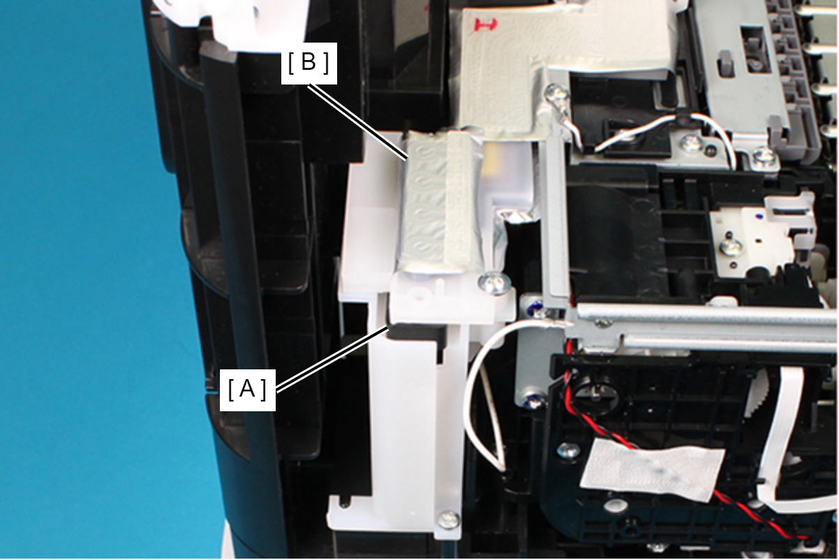 Caution / 注意
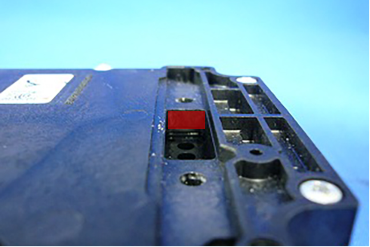
If ink is remained to ink tube joint part of Printhead, Ink Leak Check can not perform correctly. Therefore cleaning the ink surely.
Assembly / 組み立て- In order to obtain correct results from the Ink Leak Check, the ink tube joint part of the Printhead need to be cleaned.
When attaching the Ink Supply Tube Assy, make sure to clean the Ink tube joint part of Printhead using cleaning stick (code: 1709718).- Rear Section
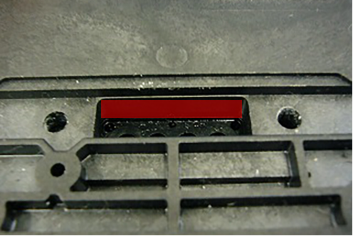
- Rear Section
-
Right side
- Bottom
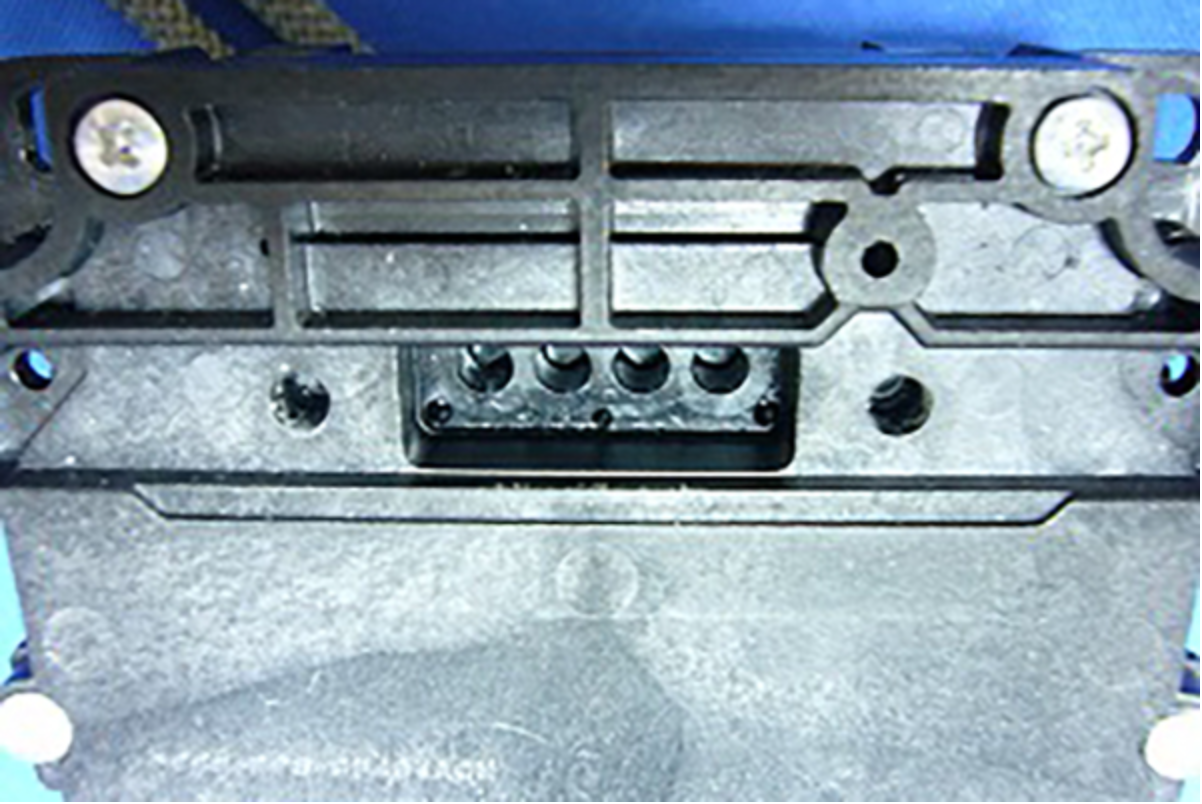
Left side
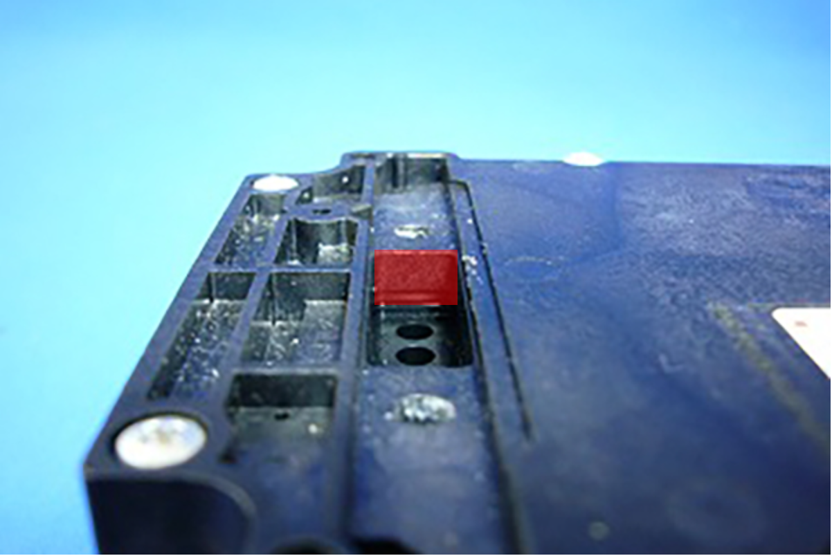
- Front Section
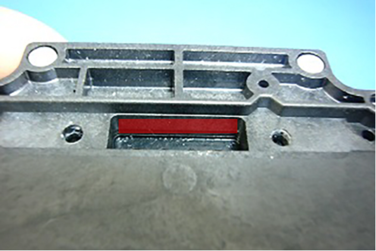
- In this product, Ink Leak Check is necessary to prevent the ink leakage due to assembly mistake.
Therefore, make sure to install the Ink Leak Check Jig when installing the Ink Tube to Printhead.
Types of Ink Leak Check Jigs
Parts name Part code Length of figure below (A) Remarks LEAK TESTER SHEET FRONT
1684353 10 mm 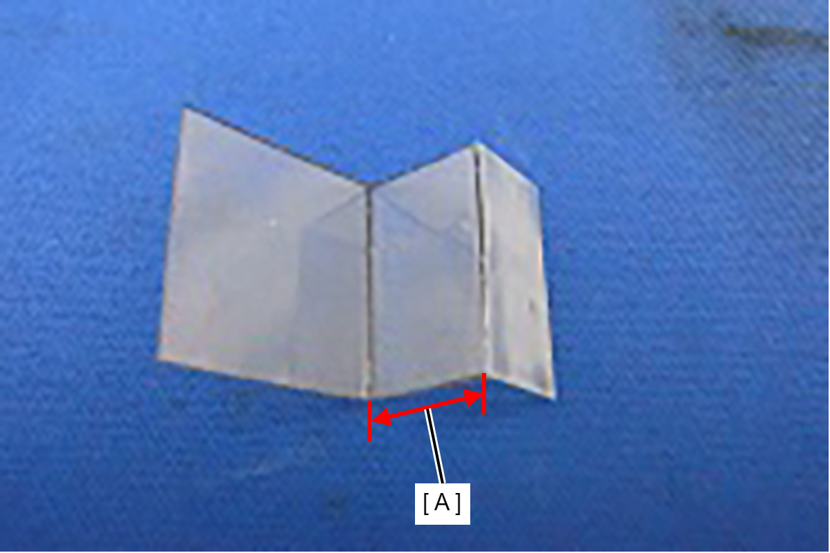
- Install the Ink Leak Check Jigs in accordance with the following procedure.
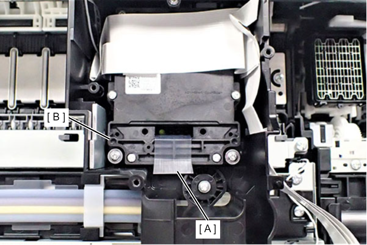
- Before using the Ink Leak Check Jig (A), push the Ink Leak Check Jigs along the folds until the fold angle become 90 degrees.
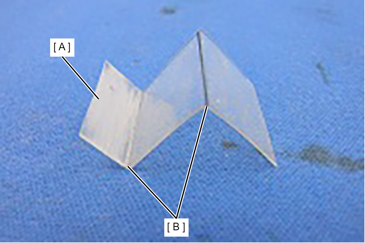
Set the Ink Leak Measurement Jig (A) to the Printhead (B).
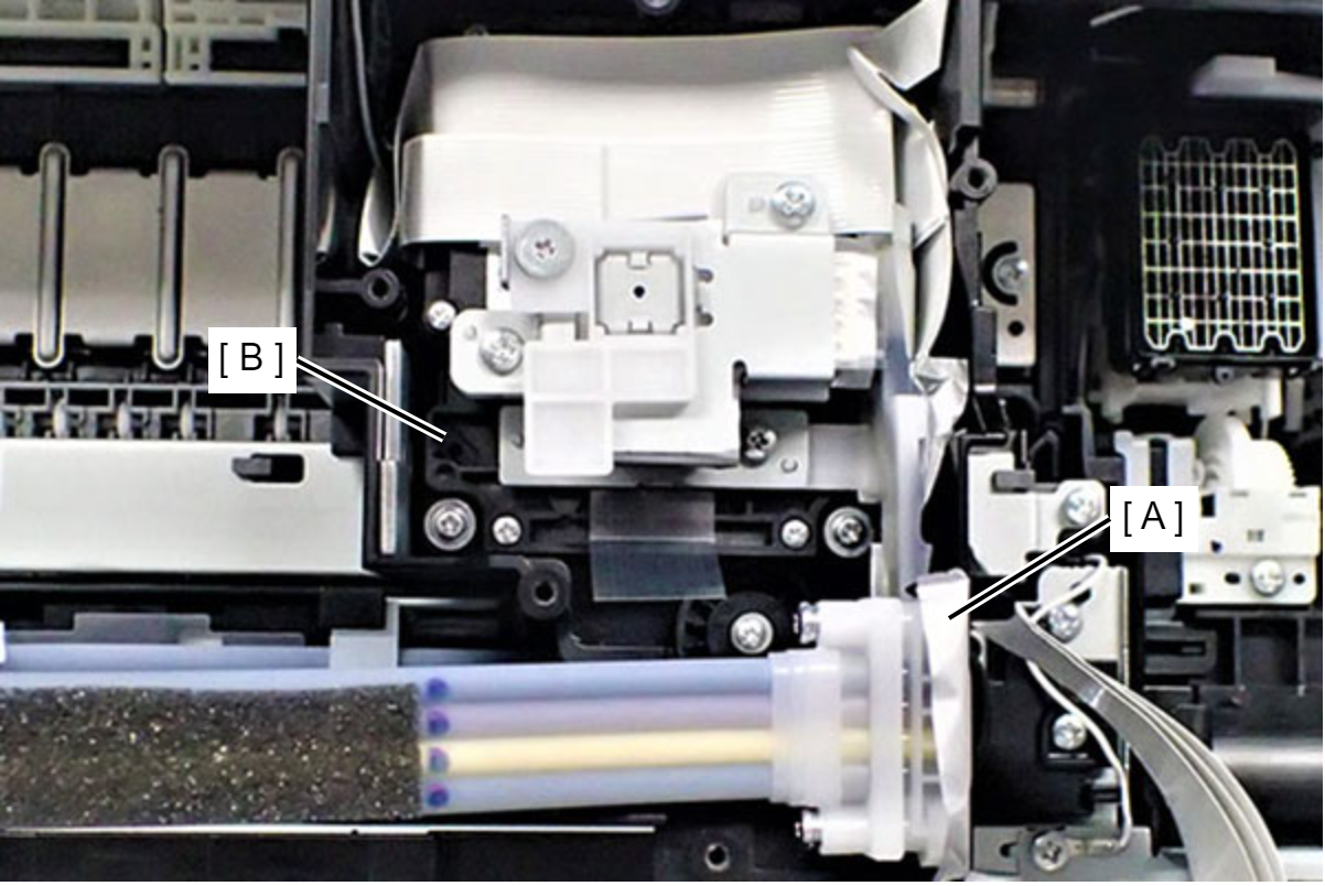
- Set the Ink Supply Tube (A) to the Printhead (B).
Caution / 注意- The smoked face of Ink Leak Measurement Jig (A) is put toward the upside.
- When installing the Ink Supply Tube Assy (A), make sure to tighten the screws using a torque driver with the specified torque.
- Screw tightening torque: 0.33 +/- 0.02 N⋅m
- In order to obtain correct results from the Ink Leak Check, the ink tube joint part of the Printhead need to be cleaned.
- Before using the Ink Leak Check Jig (A), push the Ink Leak Check Jigs along the folds until the fold angle become 90 degrees.
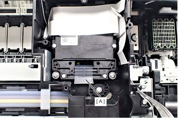
Set the Ink Leak Measurement Jig (A) to the Printhead (B).
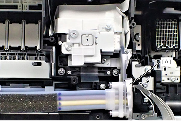
- Set the Ink Supply Tube (A) to the Printhead (B).