Preparation for the PG adjustment
 Check Point / チェックポイント Check Point / チェックポイント |
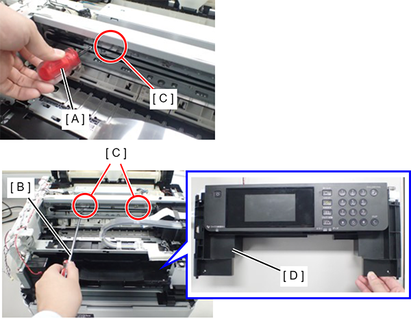
If you have a stubby screwdriver (A), this preparation is not necessary. If you haven’t a stubby screwdriver (A), remove the Front Housing (D) from the printer in the following steps to access the PG Adjustment Cam (C) by using a screwdriver (B).
|
Procedure
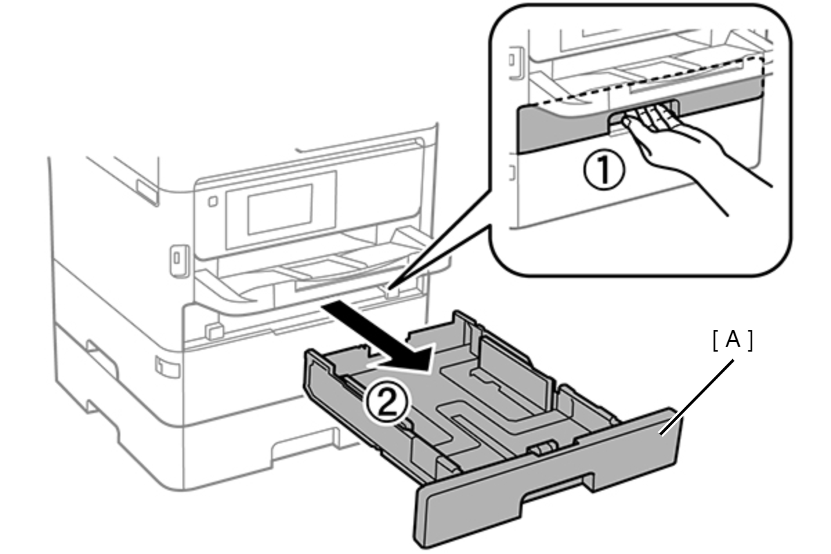
- Pull out the Paper Cassette 1 (A).
- Remove the four screws
 securing the Front Housing and the screw
 securing the cable guide.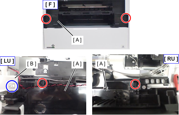
- Disconnect the three cables (B) from the connectors on the Relay Board (A) to move the Cable Guide (C).
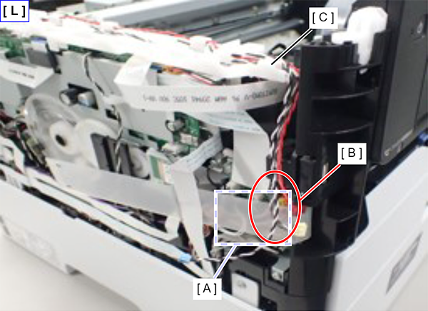
Disconnect the FFCs and cables shown below from the connectors on the Main Board while lifting the front side of the Cable Guide.
- Head FFC (CN66, CN67)
- Panel FFC (CN42): When disconnecting the Panel FFC (CN42), make sure to unlock the connector lock beforehand.
- Speaker cable (CN3) (Only WF-C579R/C579Ra)
- Cover Open Sensor cable (CN609)
- USB Interface Board cable (CN33)
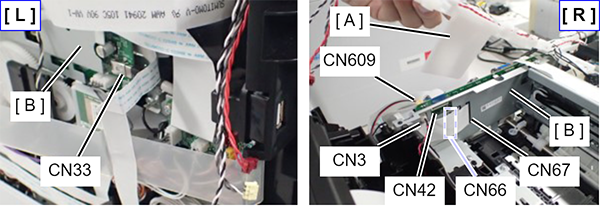
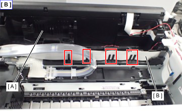
- Remove the Head FFC (B) from the tabs
 on the Front Housing (A).
 - Remove the Front Housing (A).