How to perform individual action checks
There are the following two ways to perform individual action checks so select one of the ways to perform the checks.
| Type | Program No. | Check item | Screen display | Description | Judgment method | |||||
|---|---|---|---|---|---|---|---|---|---|---|
| General | A01 | Auto Check | Auto Check Flow Individual Action | Automatically checks the printer internal state together with the initial operation and displays the mechanical states determined from the check as the results on the panel.
2. Connection state of consumables and other parts 3. Whether or not jammed paper remaining 4. Operation check of various motors 5. Check of various sensors 6. Initial operation 7. Judgment and display of mechanical state |
The check results are displayed on the panel LCD. | |||||
| Output system | A10 | CR Motor | CR Motor | Moves the CR unit back and forth to perform a CR motor failure check. | 1. Visually check that the CR action is smooth. 2. Check that the CR motor sound is not abnormal. |
|||||
| A11 | PF Motor | PF Motor/SMAP Phase Sensor | Drives the PF motor for approximately 2 seconds to perform a PF motor failure check. Inspection of the SMAP phase sensor is performed automatically while the PF motor is being driven. |
|
||||||
| Output system | A12 | APG Motor | APG Move Check | Drives the APG motor and performs APG switching to check the APG motor operation. | Visually check that the CR unit and CR shaft are operating as follows.
2. Cancel the release state on the paper guides and lower the CR shaft from PG7 to PG1. |
|||||
| A13 | ASF Motor | ASF Motor (C1) | C1 | Drives each ASF motor for approximately 2 seconds to perform an ASF motor failure check. | Check that the ASF motor sound is not abnormal. | |||||
| A14 | Additional ASF Motor (C2) | C2 | ||||||||
| A15 | Additional ASF Motor (C3) | C3 | ||||||||
| A16 | Additional ASF Motor (C4) | C4 | ||||||||
| A17 | Lift Motor/ Lift Phase Sensor | Lift (C1) Motor/Lift Phase (C1) Sensor | C1 | Check that the lift motor and lift phase sensor have not failed by operating the motor and changing the on/off state of the sensor. |
Paper cassette pulled out state The lift motor operation starts. |
|||||
| A18 | Additional Lift (C2) Motor/Lift Phase (C2) Sensor | C2 | ||||||||
| A19 | Additional Lift (C3) Motor/Lift Phase (C3) Sensor | C3 | ||||||||
| A20 | Additional Lift (C4) Motor/Lift Phase (C4) Sensor | C4 | ||||||||
| A21 | Supply Pump Motor 1 | Supply Pump Motor 1 | Drives the supply pump motor to perform a supply pump failure check. | Check that the supply pump motor sound is not abnormal. | ||||||
| A22 | Supply Pump Motor 2 | Supply Pump Motor 2 | ||||||||
| A30 | PW Sensor Solenoid | PW Sensor Solenoid | Operates the PW sensor shutter solenoid to perform the PE sensor shutter solenoid failure check. | Check the operation sound of the PW sensor shutter solenoid and check that the PE sensor shutter solenoid is operating. | ||||||
| Output system | A31 | Rear ASF Solenoid | Rear ASF Solenoid | Operates the rear ASF solenoid to perform the rear ASF solenoid failure check. | Check that the rear ASF solenoid is operating as follows. (The check operation is executed in the following sequence.) 1. Check the operation of the rear ASF solenoid visually and by its sound. 2. Check that the LD roller rotates. 3. After the LD roller rotates, check from the sound that the motor drive one way clutch is idling due to the one way clutch. |
|||||
| A32 | NIP Solenoid/Sensor | NIP Solenoid/Sensor | Operates the Intermediate Release Solenoid to perform the Intermediate Release Solenoid and nip release solenoid sensor failure check. | 1. Check that the solenoid is operating both visually and by its sound. 2. Whether or not the Intermediate Nip Release Sensor is switched ON/OFF normally is displayed on the panel LCD. |
||||||
| A34 | Main Eject Tray Operation Check | Main Eject Tray Operation Check | Check whether the automatic extension of the Main Eject Tray works properly. | 1. Retract the tray. 2. Check whether the tray is automatically extended when the setting is enabled. 3. Retract the tray again to check whether the tray is kept in the retracted state. |
||||||
| Input system | A40 | ALL Sensor Check | ALL Sensor Check | Accesses each sensor to check the ON/ OFF of the sensor for each type of driving and sequence. | Manually switch the target sensor ON/OFF and check that the sensor state displayed on the panel LCD changes. Regarding the detail of All sensor check, refer to “All Sensor Check Items”. |
|||||
| A41 | Feed/Eject Check (Paper pass check) | Main cassette Feed - Eject check single (C1) | Simplex-C1 | Check that the various sensors related to the main unit cassette have not failed and actually pass paper through and check the ease of feeding and that sensor output is not abnormal. | The check results are displayed on the panel LCD. | |||||
| A42 | Main cassette Feed - Eject check single (C2) | Simplex-C2 | ||||||||
| A43 | Main cassette Feed - Eject check single (C3) | Simplex-C3 | ||||||||
| A44 | Main cassette Feed - Eject check single (C4) | Simplex-C4 | ||||||||
| Input system | A45 | Feed/Eject Check (Paper pass check) |
Additional cassette Feed - Eject check single (RASF) | Simplex-Rear ASF | Check that the various sensors related to the main unit cassette have not failed and actually pass paper through and check the ease of feeding and that sensor output is not abnormal. | The check results are displayed on the panel LCD. | ||||
| A46 | Additional cassette Feed - Eject check Double (C1) | Duplex-C1 | ||||||||
| A47 | Main cassette Feed - Eject check Double (C2) | Duplex-C2 | ||||||||
| A48 | Additional cassette Feed - Eject check Double (C3) | Duplex-C3 | ||||||||
| A49 | Additional cassette Feed - Eject check Double (C4) | Duplex-C4 | ||||||||
| A50 | Feed/Eject Sensor Check | Main cassette Feed - Eject sensor check (C1) | C1 | Check that the various sensors related to the main unit cassette have not failed and actually pass paper through and check the ease of feeding and that sensor output is not abnormal. | The setting state of the current paper cassette is displayed on the panel LCD. Check that the panel display changes to match the paper cassette state depending on insertion or pulling out of the paper cassette, movement of the edge guides, and whether or not there is paper. | |||||
| A51 | Additional cassette Feed - Eject sensor check (C2) | C2 | ||||||||
| A52 | Additional cassette Feed - Eject sensor check (C3) | C3 | ||||||||
| A53 | Additional cassette Feed - Eject sensor check (C4) | C4 | ||||||||
| A54 | Additional cassette Feed - Eject check (RASF) | Rear ASF | ||||||||
| A55 | PW Sensor Shutter Check | Shutter Check-PW | Check that there is no problem with the operation of the shutter that is attached to the CR for reducing the amount of mist on the PW sensor. | The check results are displayed on the panel LCD. | ||||||
| Input system | A56 | APG Sensor Check | APG Sensor | Check that the APG phase sensor has not failed by changing the on/off state of the sensor and checking whether the sensor is normal or abnormal. | The check results are displayed on the panel LCD. | |||||
| A57 | Humidity Sensor Check | Temp/hum. Sensor | Check that the temperature and humidity sensors are operating normally. | 1. Check the output values of the temperature and humidity sensors. (If there is a sensor error, use the following values as a guide for making a judgment.)
|
||||||
| A58 | Ink End Sensor Check | Ink End Sensor | Check the ink end sensor state with ink present. | Check that the sensor state on the panel LCD changes as a result of moving the ink end sensor lever. | ||||||
| A62 | Ink Leak Sensor Check | Ink Leak Sensor | Check the state of the ink leak sensor. | The check results are displayed on the panel LCD. | ||||||
| Auxiliary functions | A02 | CR Unlock Power OFF | CR Unlock Power OFF | Turns off the power from the CR unlock state. | --- | |||||
All Sensor Check Items
| Category | Display | Applicable Sensor | Confirmation method | ||||||
|---|---|---|---|---|---|---|---|---|---|
| Main | Front Cover Sensor | Front Cover Sensor | Confirm the state of sensor is changing by opening/closing the corresponding cover. | ||||||
| Rear Unit Cover Sensor | Duplex Print Cover Open Sensor | ||||||||
| Ink Rear Cover Sensor | Paper Jam Clear Cover Open Sensor | ||||||||
| Ink Cover Sensor | Ink Pack Cover Open Sensor | ||||||||
| PE Sensor | PE Sensor | 1. Print a PE Sensor check pattern. 2. Open the rear cover, and remove the Duplex Print Unit. 3. Place the PE Sensor check pattern directly underneath the PE Sensor, and check that the sensor state changes. |
|||||||
| Nip Release Sensor | Intermediate Nip Release Sensor | Confirm the state of sensor is changing by installing/removing the Duplex Unit. | |||||||
| Feed Sensor | Feed Sensor (Main Product side) | Confirm the state of sensor is changing by moving the Feed Sensor Lever. | |||||||
| Rear Unit Sensor | Duplex Unit Paper Detector | Confirm the state of sensor is changing by moving the Duplex Unit Paper Detector. | |||||||
| Ink Feed Sensor | RIPS Feed Sensor | Confirm the state of sensor is changing by moving the RIPS Feed Sensor. | |||||||
| Ink End Sensor BK | Ink End Sensor 1 | Confirm the state of sensor is changing by moving the Ink End Sensor Lever. * When moving the Ink End Sensor Lever, make sure not to damage the Buffer. |
|||||||
| Ink End Sensor MG | Ink End Sensor 2 | ||||||||
| Ink End Sensor CY | Ink End Sensor 3 | ||||||||
| Ink End Sensor YE | Ink End Sensor 4 | ||||||||
| Ink Leak Sensor 1 | Ink Leak Sensor 1 | --- | |||||||
| Ink Leak Sensor 2 | Ink Leak Sensor 2 | ||||||||
| Ink Leak Sensor 3 | Ink Leak Sensor 3 | ||||||||
| Cassette1 | Cassette Detection Sensor | Cassette Detection Sensor | Confirm the state of sensor is changing by installing /removing the paper cassette (C1). | ||||||
| Paper Detection Sensor | Paper Detection Sensor (FASF) | Confirm the state of sensor is changing by changing the paper set condition of paper cassette (C1). | |||||||
| Hopper Position Sensor | Hopper Up/down Sensor | Confirm the state of sensor is changing by installing /removing the paper cassette (C1). | |||||||
| Paper Size Sensor 1/2 | Cassette paper size sensor (1), (2) | Confirm the state of sensor is changing by moving the Edge Guide of paper Cassette(C1). | |||||||
| PE Sensor | PE Sensor | Confirm the state of sensor is changing by pushing the PE sensor by paper etc. | |||||||
| Feed Sensor | Feed Sensor (Main Product side) | Confirm the state of sensor is changing by moving the Feed Sensor Lever. | |||||||
| Cassette2 | Cassette Detection Sensor | Cassette Detection Sensor | Confirm the state of sensor is changing by installing /removing the paper cassette (C2). | ||||||
| Paper Detection Sensor | Paper Detection Sensor | Confirm the state of sensor is changing by changing the paper set condition of paper cassette (C2). | |||||||
| Hopper Position Sensor | Paper Detection Sensor | Confirm the state of sensor is changing by installing /removing the paper cassette (C2). | |||||||
| Paper Size Sensor 1/2 | Cassette paper size sensor (1), (2) | Confirm the state of sensor is changing by moving the Edge Guide of paper Cassette(C2). | |||||||
| PE Sensor | PE Sensor | Confirm the state of sensor is changing by pushing the PE sensor by paper etc. | |||||||
| Feed Sensor | Feed Sensor (Option Cassette side) | Confirm the state of sensor is changing by moving the Feed Sensor Lever. | |||||||
| Cassette3 | Cassette Detection Sensor | Cassette Detection Sensor | Confirm the state of sensor is changing by installing /removing the paper cassette (C3). | ||||||
| Paper Detection Sensor | Paper Detection Sensor | Confirm the state of sensor is changing by changing the paper set condition of paper cassette (C3). | |||||||
| Hopper Position Sensor | Paper Detection Sensor | Confirm the state of sensor is changing by installing /removing the paper cassette (C3). | |||||||
| Paper Size Sensor 1/2 | Cassette paper size sensor (1), (2) | Confirm the state of sensor is changing by moving the Edge Guide of paper Cassette(C3). | |||||||
| PE Sensor | PE Sensor | Confirm the state of sensor is changing by pushing the PE sensor by paper etc. | |||||||
| C3 Feed Sensor | Feed Sensor (Option Cassette side) | Confirm the state of sensor is changing by moving the Feed Sensor Lever. | |||||||
| Cassette4 | Cassette Detection Sensor | Cassette Detection Sensor | Confirm the state of sensor is changing by installing /removing the paper cassette (C4). | ||||||
| Paper Detection Sensor | Paper Detection Sensor | Confirm the state of sensor is changing by changing the paper set condition of paper cassette (C4). | |||||||
| Hopper Position Sensor | Paper Detection Sensor | Confirm the state of sensor is changing by installing /removing the paper cassette (C4). | |||||||
| Paper Size Sensor 1/2 | Cassette paper size sensor (1), (2) | Confirm the state of sensor is changing by moving the Edge Guide of paper Cassette(C4). | |||||||
| PE Sensor | PE Sensor | Confirm the state of sensor is changing by pushing the PE sensor by paper etc. | |||||||
| C4 Feed Sensor | Feed Sensor (Option Cassette side) | Confirm the state of sensor is changing by moving the Feed Sensor Lever. | |||||||
| Rear ASF | Paper Detection Sensor | Paper Detection Sensor (Rear ASF Unit) | Confirm the state of sensor is changing by setting the paper to Rear ASF Unit. | ||||||
| PE Sensor | PE Sensor | Confirm the state of sensor is changing by pushing the PE sensor by paper etc. | |||||||
| Eject Tray | Phase Sensor | Main Eject Tray phase sensor | Confirm the state of sensor is changing by shielding the light of the Main Eject Tray phase sensor. | ||||||
| Cam Phase Sensor | Main Eject Tray cam phase sensor | Confirm the state of sensor is changing by shielding the light of the Main Eject cam phase sensor. | |||||||
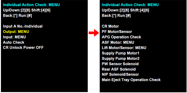
A:Select a check item from the list to execute the check.
- Select “Output: MENU (output system parts)” or “Input: MENU (input system parts)” from the individual action check mode menu screen.
- Select the target check items from the corresponding menu to execute the checks.
B:Enter the program number execute.
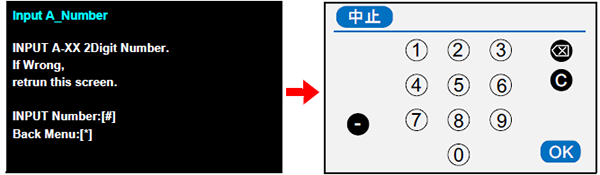
Select “A00 Individual -Input A Number” from the individual action check mode menu.
Press the [#] button to display the program number input screen. To return to the previous menu screen, press the [*] button.
- When the program number input screen appears, refer to the check item list Verification Items listand then enter the program number of the corresponding check item and press the [OK] button. (Example: In the case of the CR motor check, enter “10”.)