Nip Release Solenoid
 Adjustment / 調整 Adjustment / 調整 |
When replacing/removing this part, refer to the following pages and make sure to perform the specified operations including the required adjustments. |
- Remove the two screws.
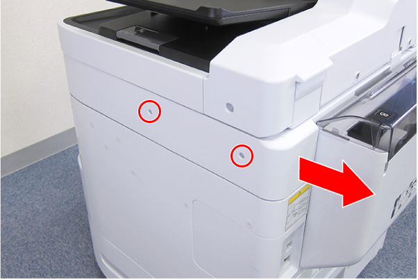
 : C.B.S-TITE-SCREW-3x8-F.ZN-3C
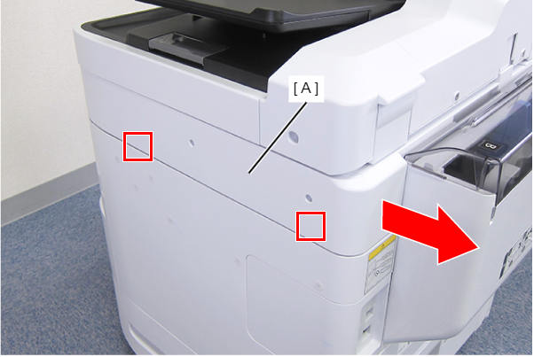
- Disengage the two hooks by sliding the Right SC Cover (A) toward the rear of the product, then remove it.
- Remove the screw.
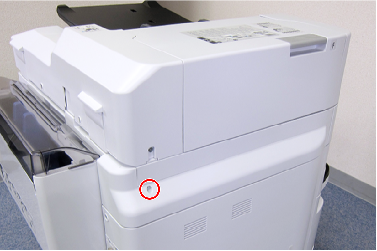
- : C.B.S-TITE-SCREW-3x8-F.ZN-3C
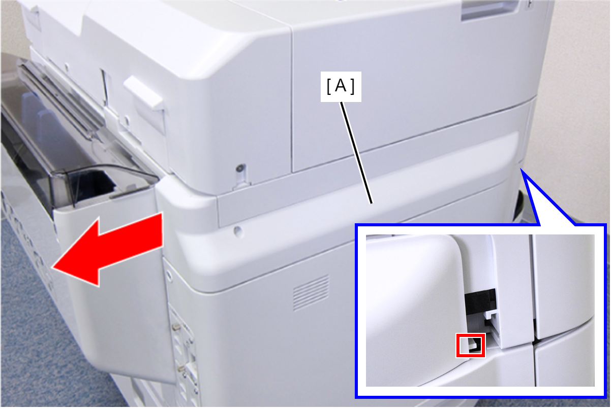
- Slide the Left SC Cover (A) toward the rear of the product to disengage the tab.
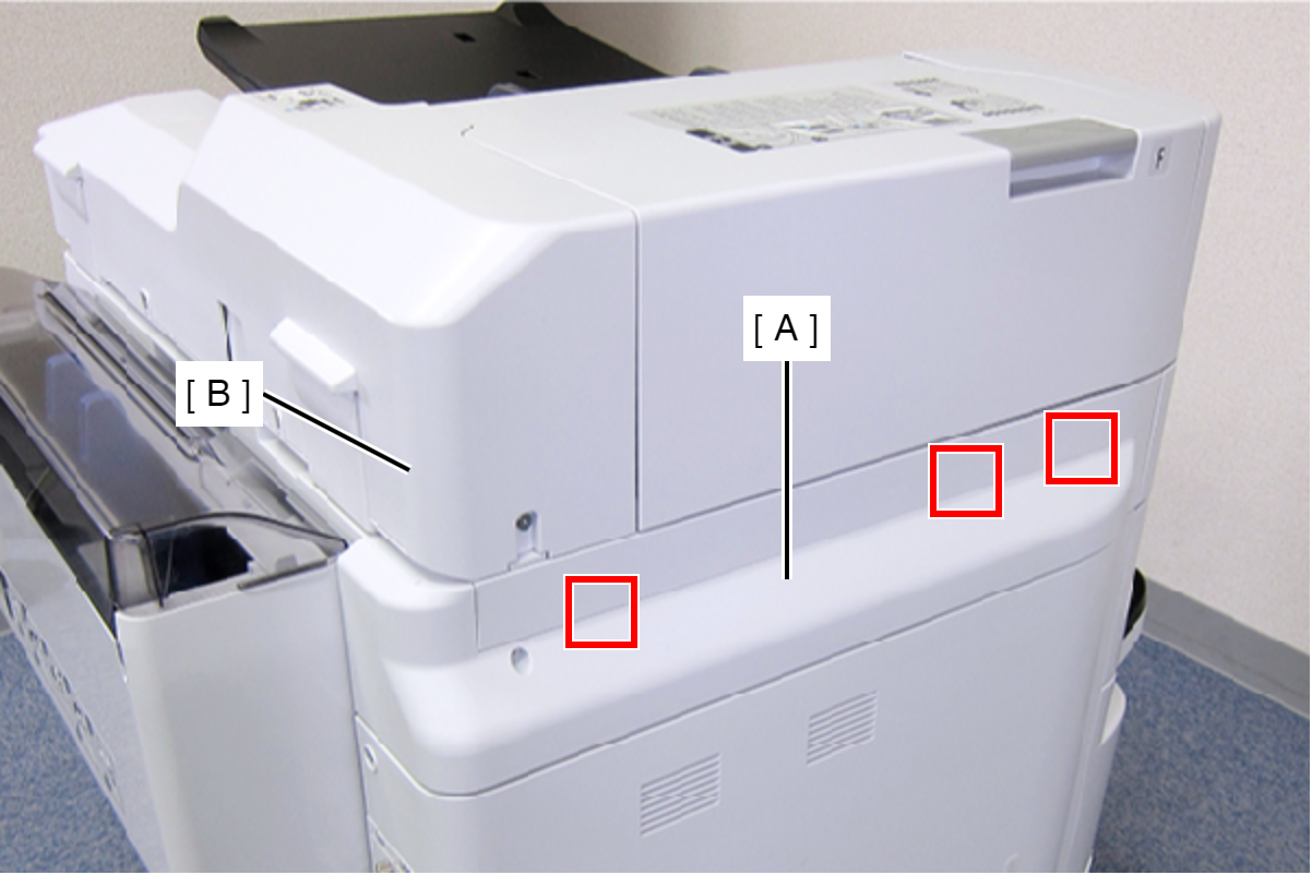
- Disengage the three tabs by inserting a flathead screwdriver into the gap between the Left SC Cover (A) and the ADF Unit (B), and then remove the Left SC Cover (A).
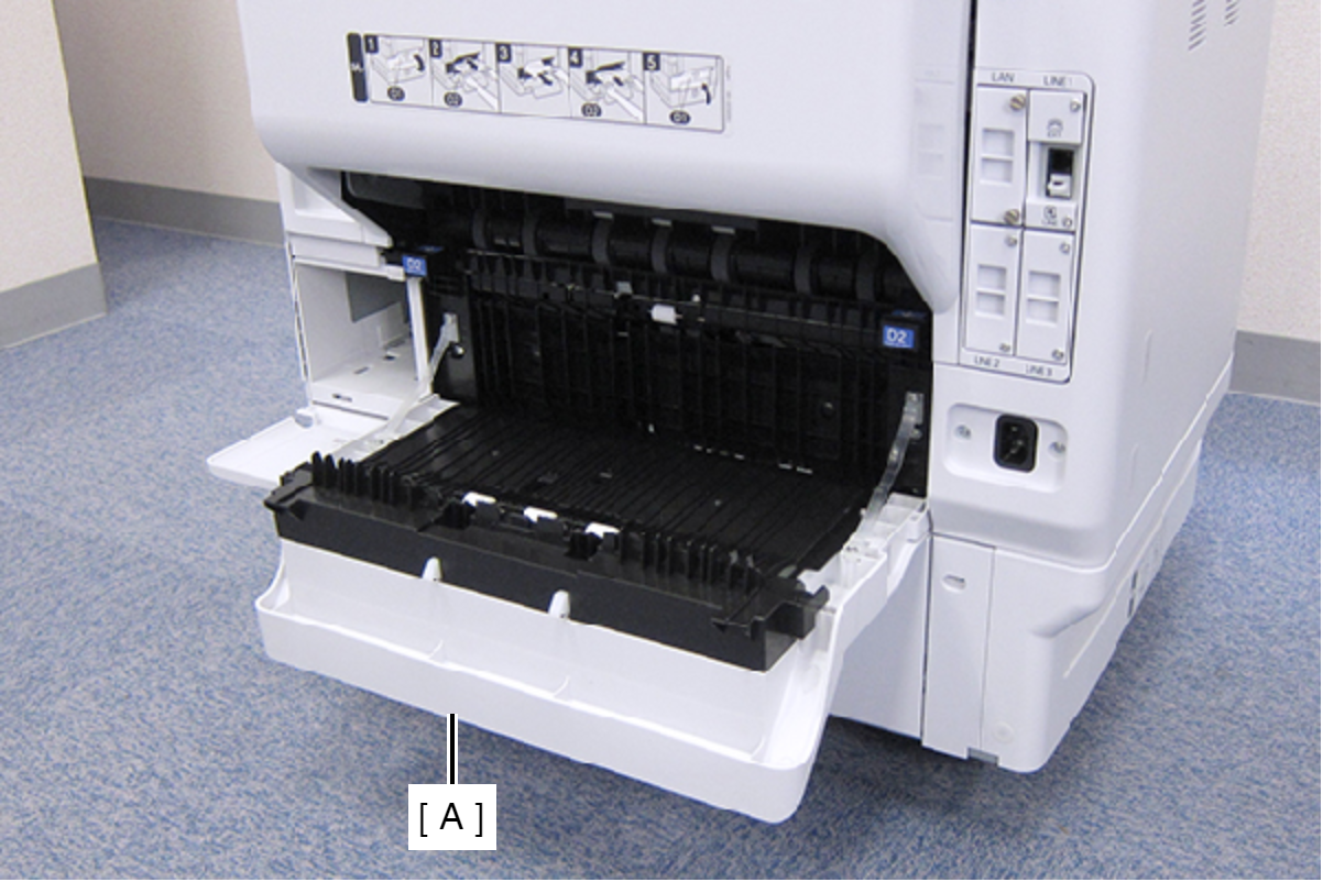
- Open the Duplex Print Cover (A).
- Remove the two screws, then remove the Connector Cover (A).
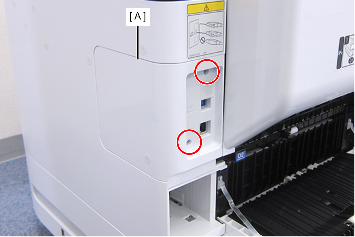
- : C.B.S-TITE-SCREW-3x8-F.ZN-3C
- Remove the two screws, then remove the Right Housing Assy (A) toward the rear of the product.
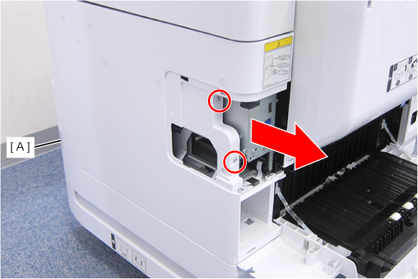
- : C.B.S-TITE-SCREW-3x8-F.ZN-3C
- Remove the two screws.
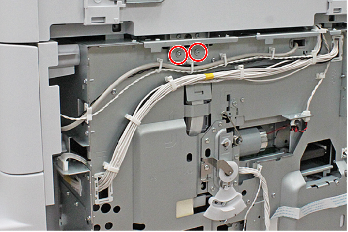
- : C.C.S-TITE-3x6-F.ZN-3C
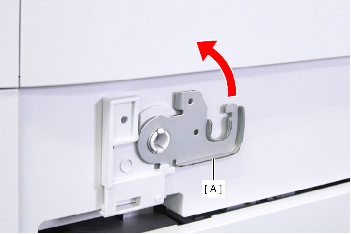
- Raise the ADF Stopper (A) to lock the ADF Unit.
- Secure the ADF Stopper with one of the screws you removed at step 1.
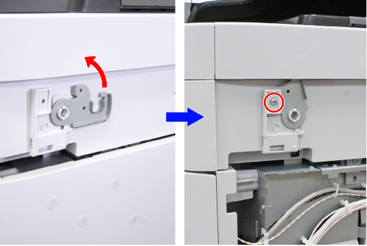
- : C.C.S-TITE-3x6-F.ZN-3C
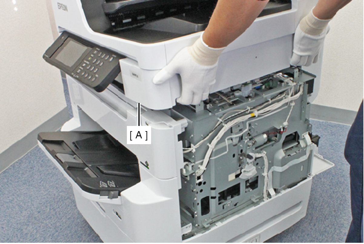
- Hold the ADF/SCN Unit (A) with both hands as shown above, and open the ADF/SCN Unit (A).
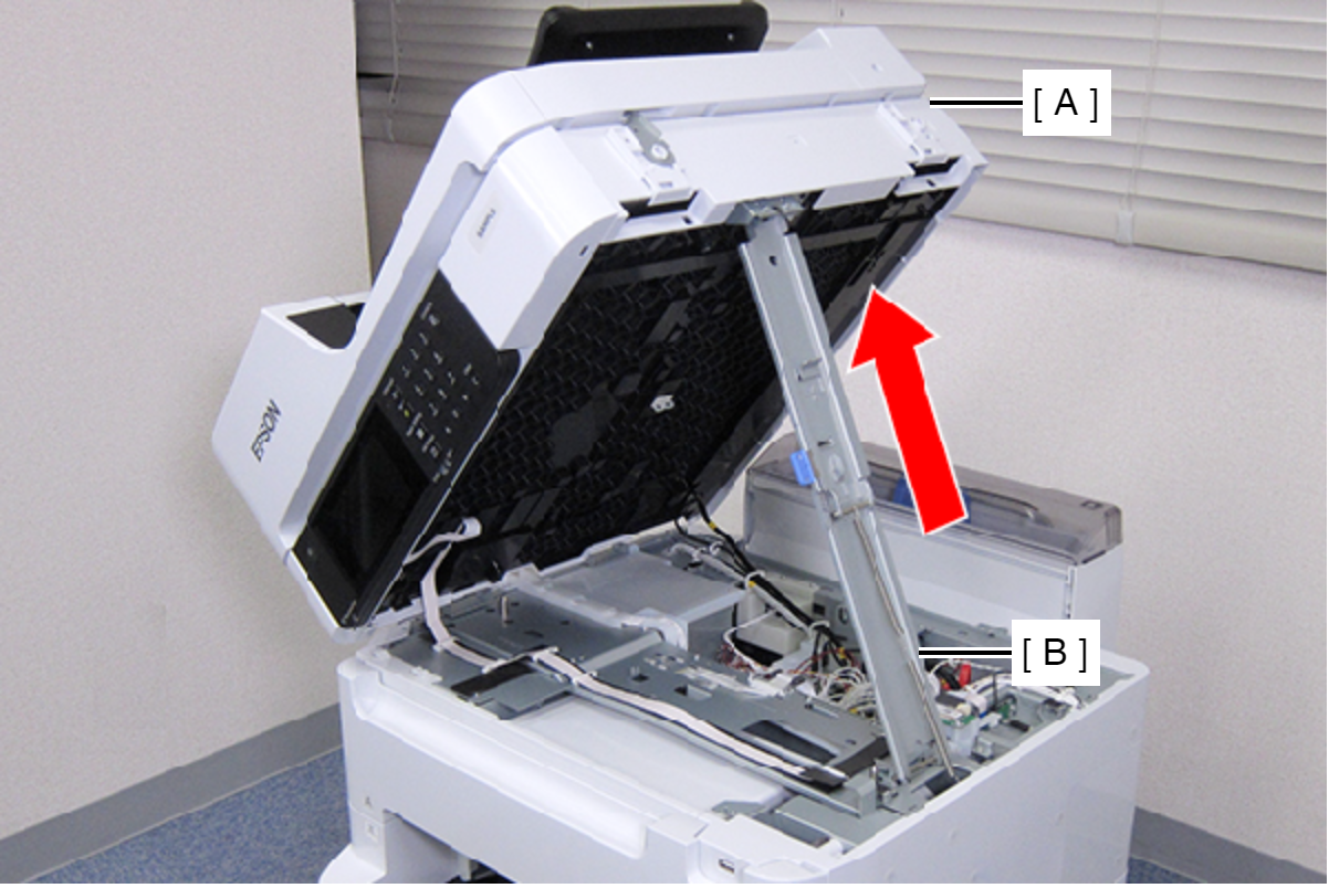
- Open the ADF/SCN Unit (A) and extend the support stand (B) as far as it goes, then support theADF/SCN Unit (A) with the support stand.
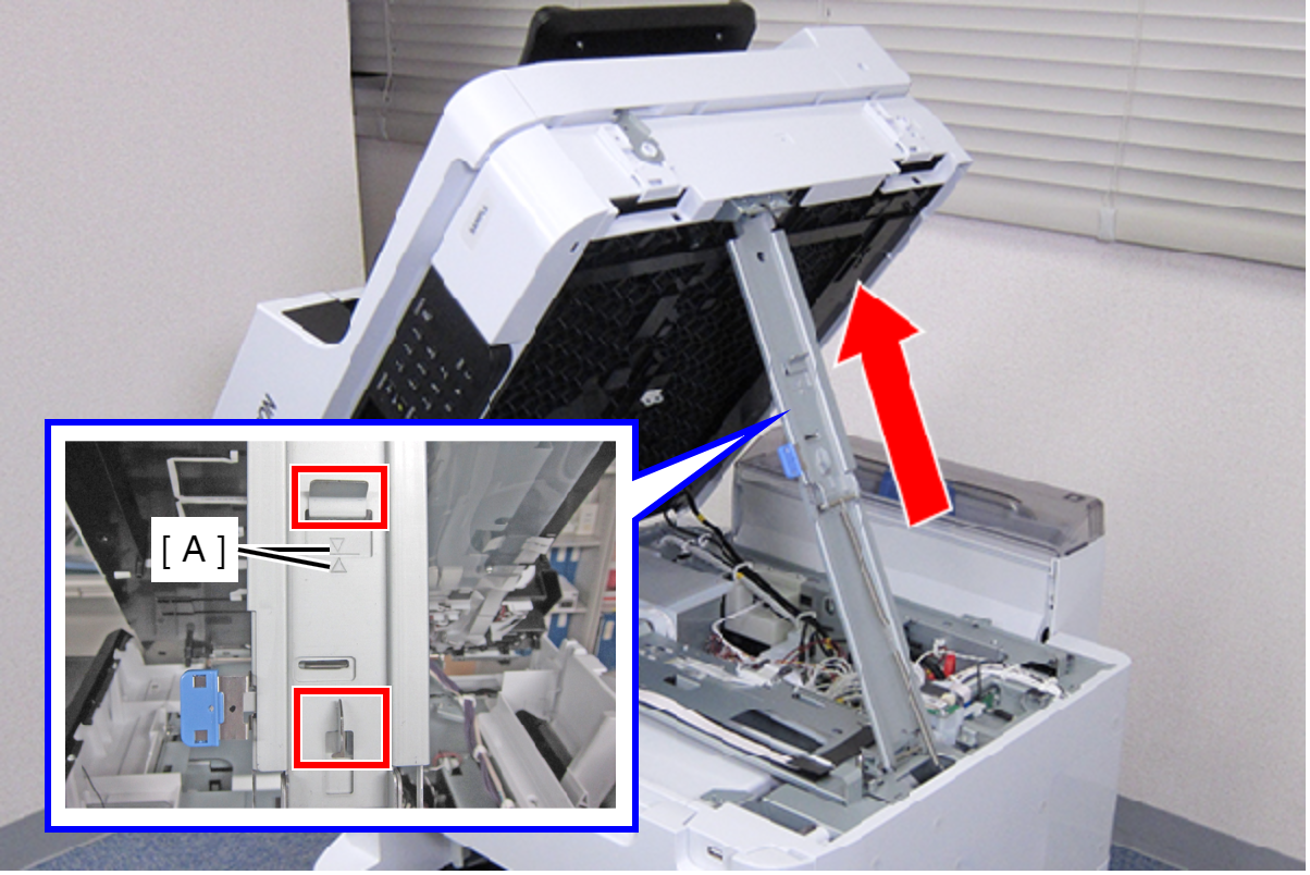
 Caution / 注意
Make sure that the extended support stand is fixed with the two hooks, and the two triangle marks face to each other.
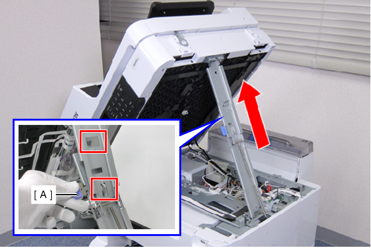
 Check Point / チェックポイント
When closing the ADF/SCN Unit, hold down the switch on the support stand and raise the ADF/SCN Unit in the direction of the arrow to disengage the two hooks, then fold the support stand.
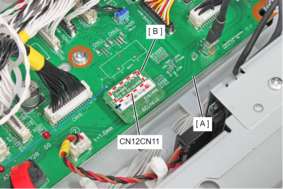
- Remove the TPM Board (B) from the connectors (CN12CN11) of the PCB Mechanism Relay Board (A).
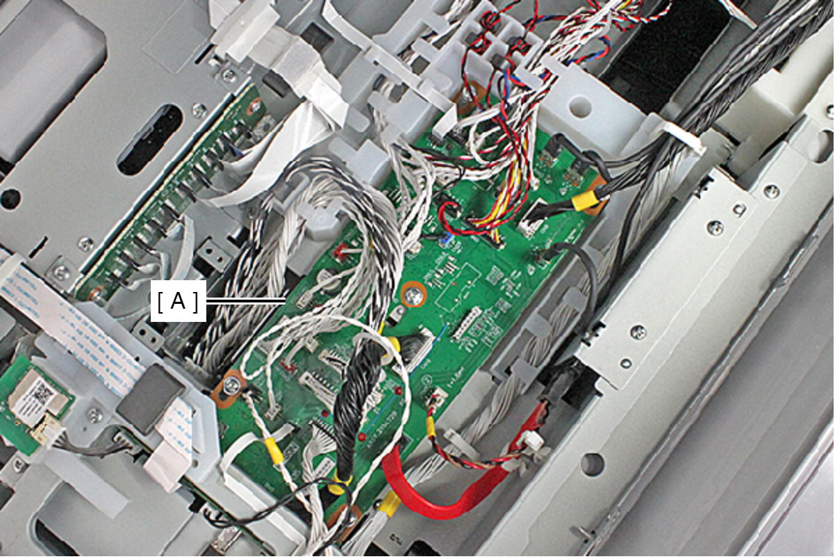
- Remove the cable/FFC from all connectors of the PCB Mechanism Relay Board (A).
 Check Point / チェックポイント
PCB Mechanism Relay Board Connectors: Cables connected to CN7, CN9, CN10, CN26, CN37, and CN38 are fastened by the connector lock.
- Release all cable/FFC routed in the Relay Harness Cover (A).
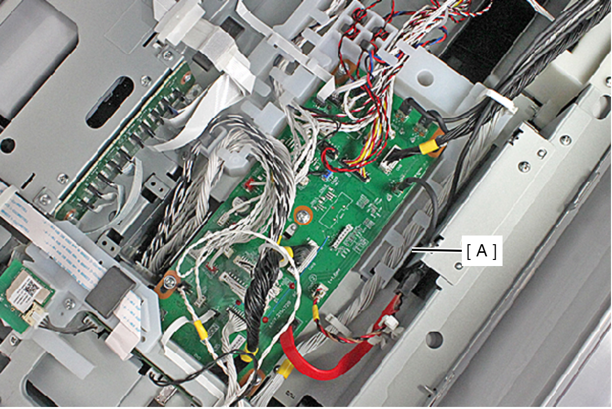
- Remove the screw, and remove the Relay Harness Cover (A).
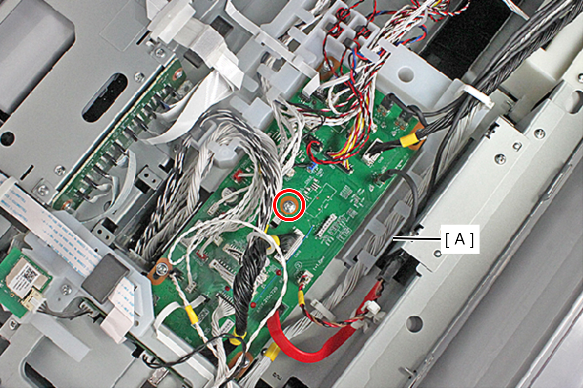
- : C.B.S-TITE-P4-SCREW-3x8-F.ZN-3C
 Assembly / 組み立て
When routing the cable/FFC to the Relay Harness Cover, refer to the photo above.
- Remove the five screws fastening the PCB Mechanism Relay Board (A).
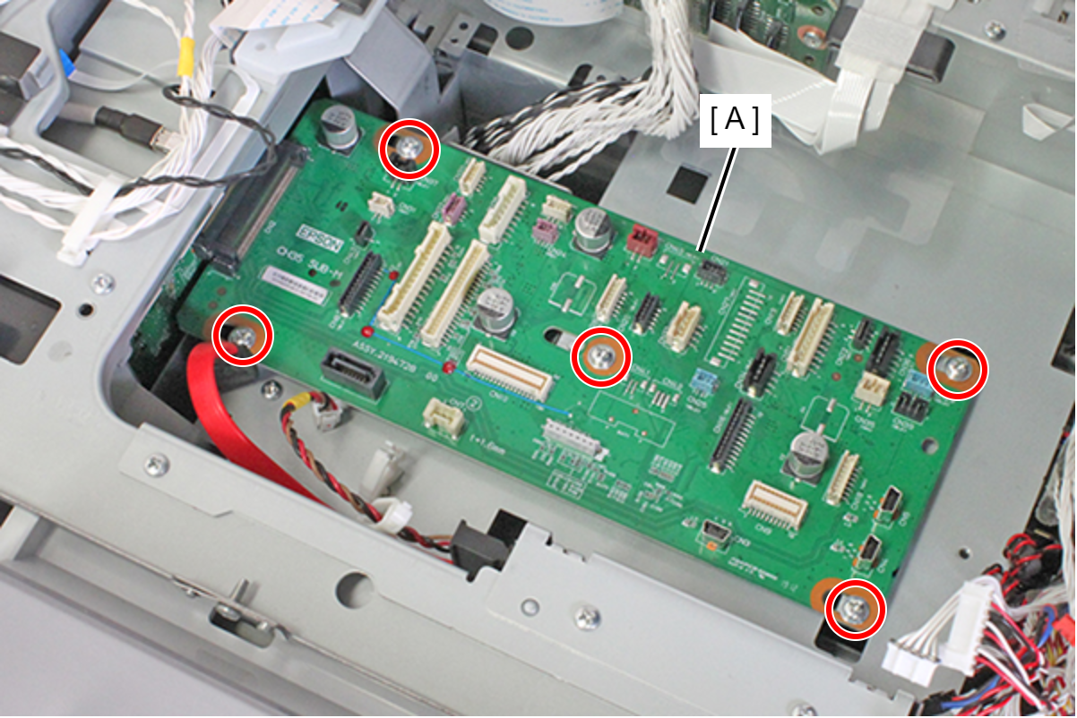
- : C.B.S-TITE-P4-SCREW-3x8-F.ZN-3C
- Slide the PCB Mechanism Relay Board (A) in the direction of the arrow to remove the connector (CN2) connecting to the Main Board (B) and remove the PCB Mechanism Relay Board.
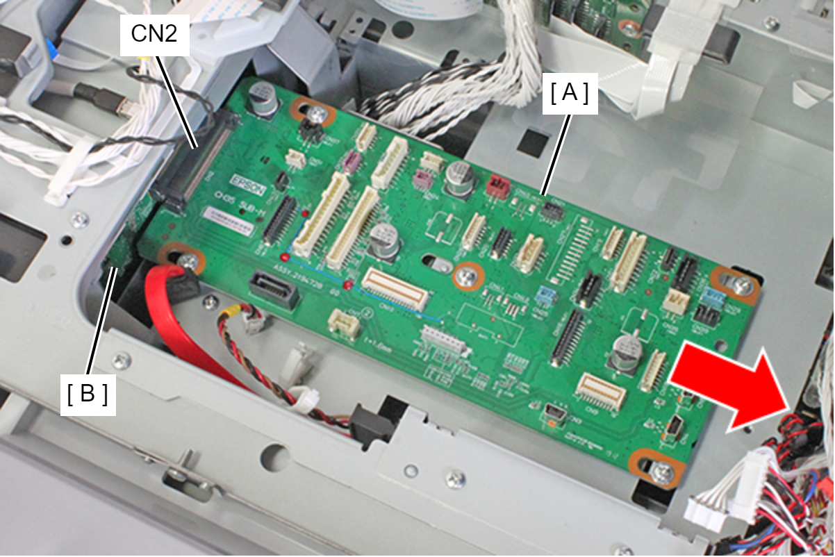
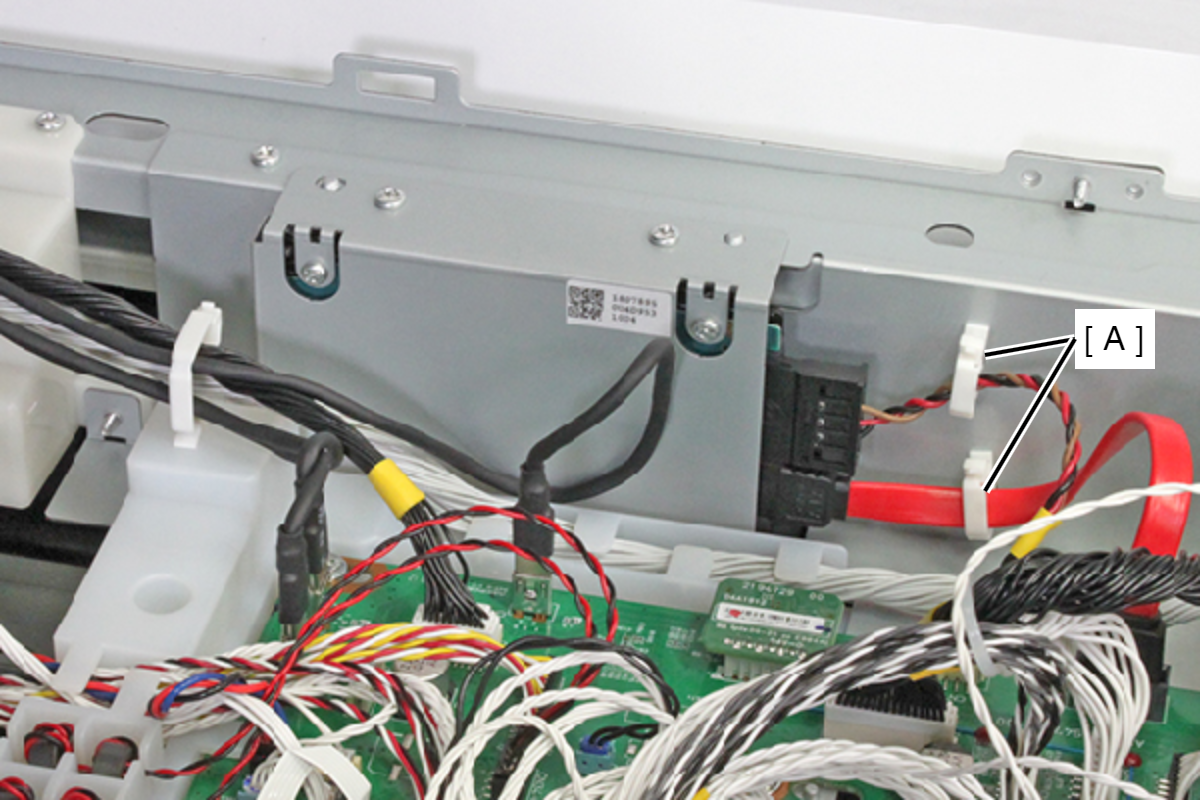
- Release each cable from the two clamps (A).
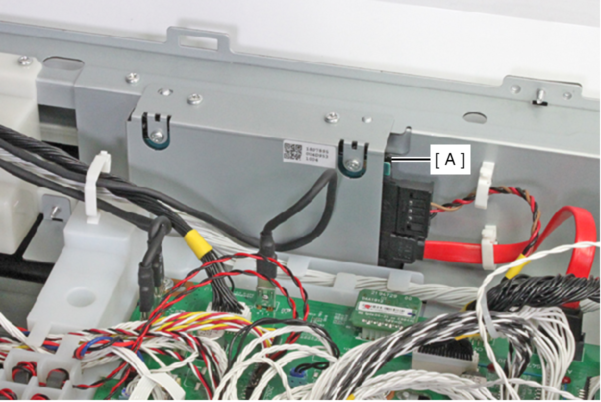
- Remove the two cables from the connector of the HDD (A).
- Remove the three screws, and remove the HDD Assy (A).
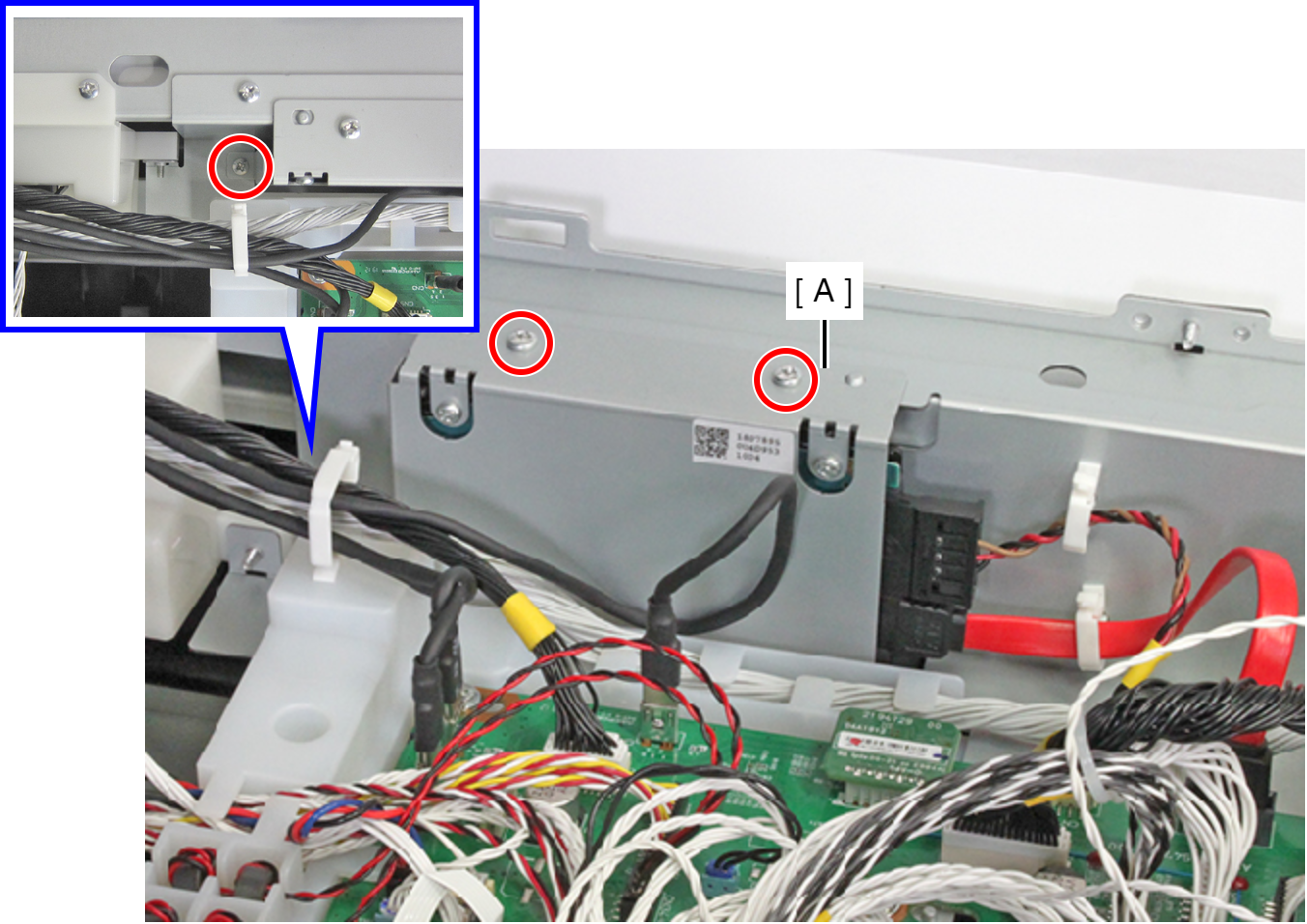
- : C.B.S-TITE-SCREW-3x8-F.ZN-3C
- Remove the two screws, then remove the Rear ASF Unit (A).
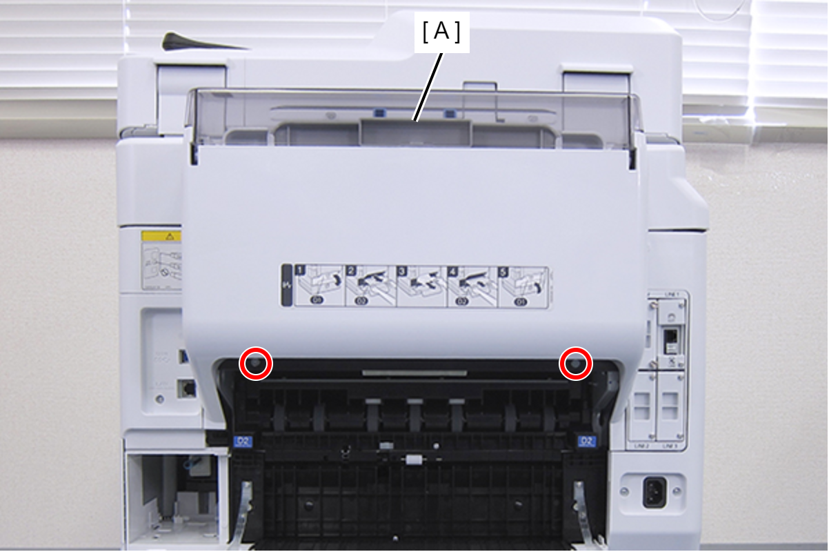
- : C.SHOULDER S-TITE,3X5
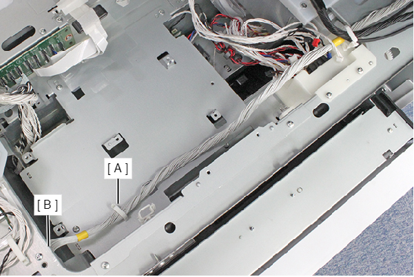
- Release the cable from the clamp (A) and remove it from the connector (CN503 (with hook)) (B) of the Main Board.
- Remove the seven screws, and remove the PCB Mechanism Relay Board Mounting Plate (A).
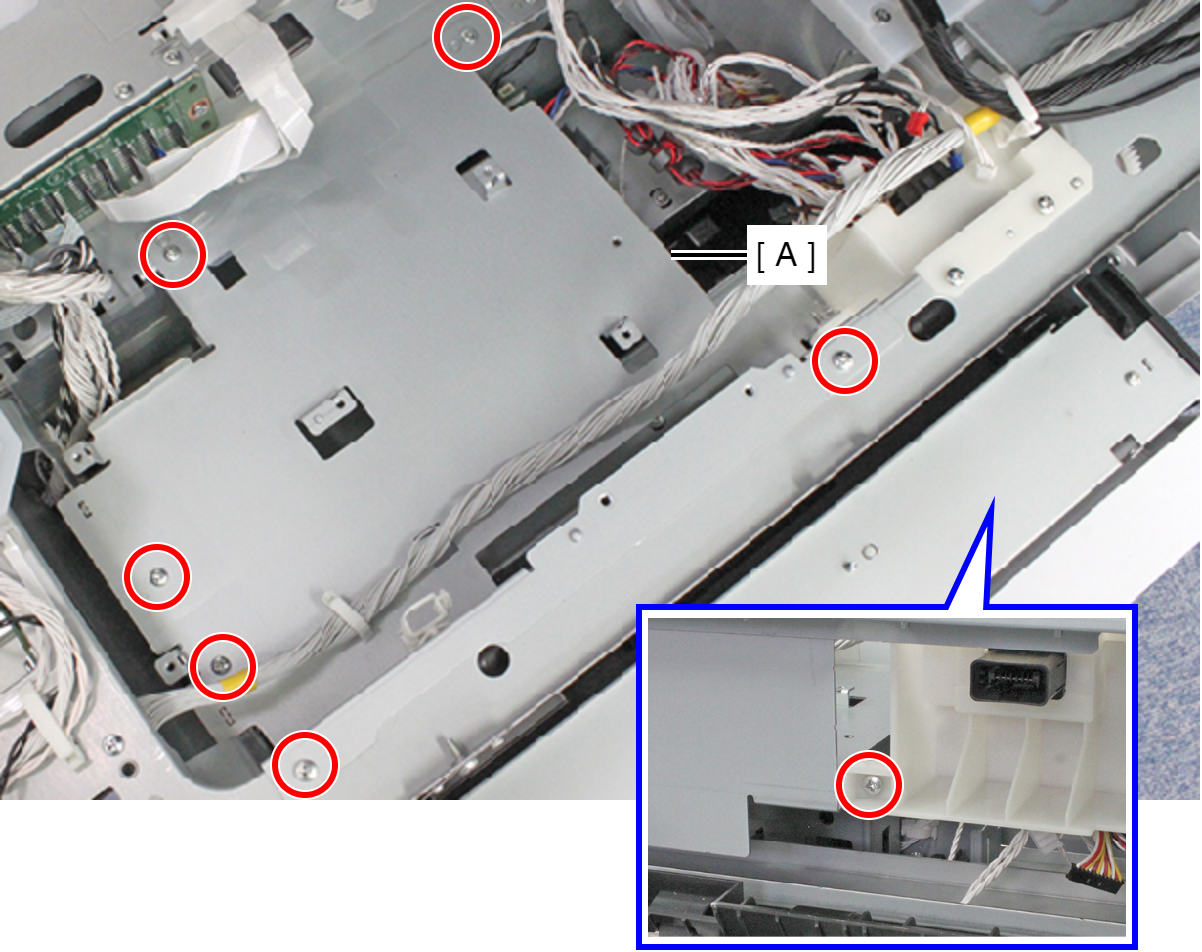
- : C.B.S-TITE-SCREW-3x8-F.ZN-3C
- Remove the screw, and remove the Intermediate Nip Release Sensor Assy (A).
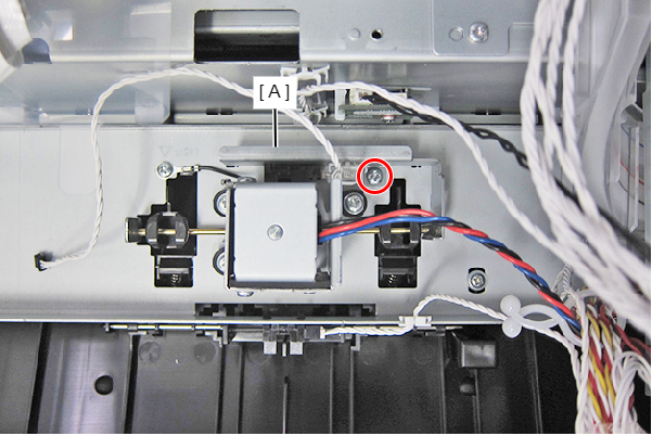
- : C.B.S-TITE-SCREW-3x8-F.ZN-3C
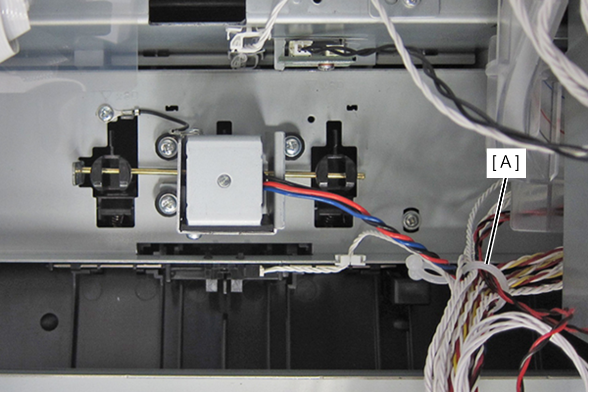
- Release the cable from the Cable Clips (A).
- Remove the screw fastening the grounding wire (A).
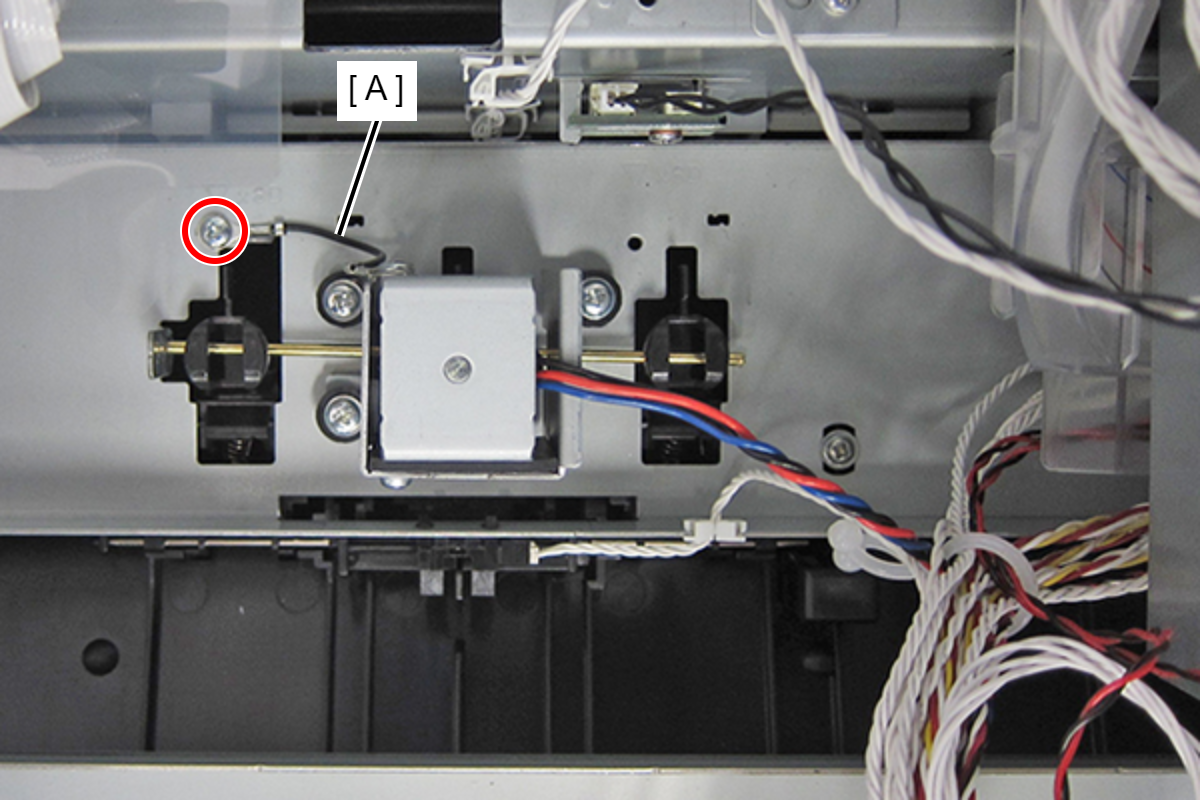
- : C.B.S-TITE-SCREW-3x8-F.ZN-3C
- Remove the three screws fastening the Intermediate Release Solenoid (A).
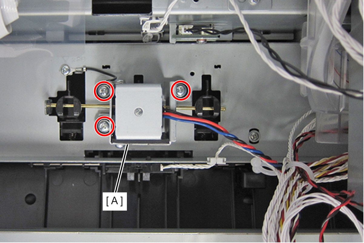
- : C.B.S-TITE-P4-SCREW-3x12-F.ZN-3C
- Pull the Nip Release Shaft (A) in the direction of the arrow and remove the Intermediate Release Solenoid (B).
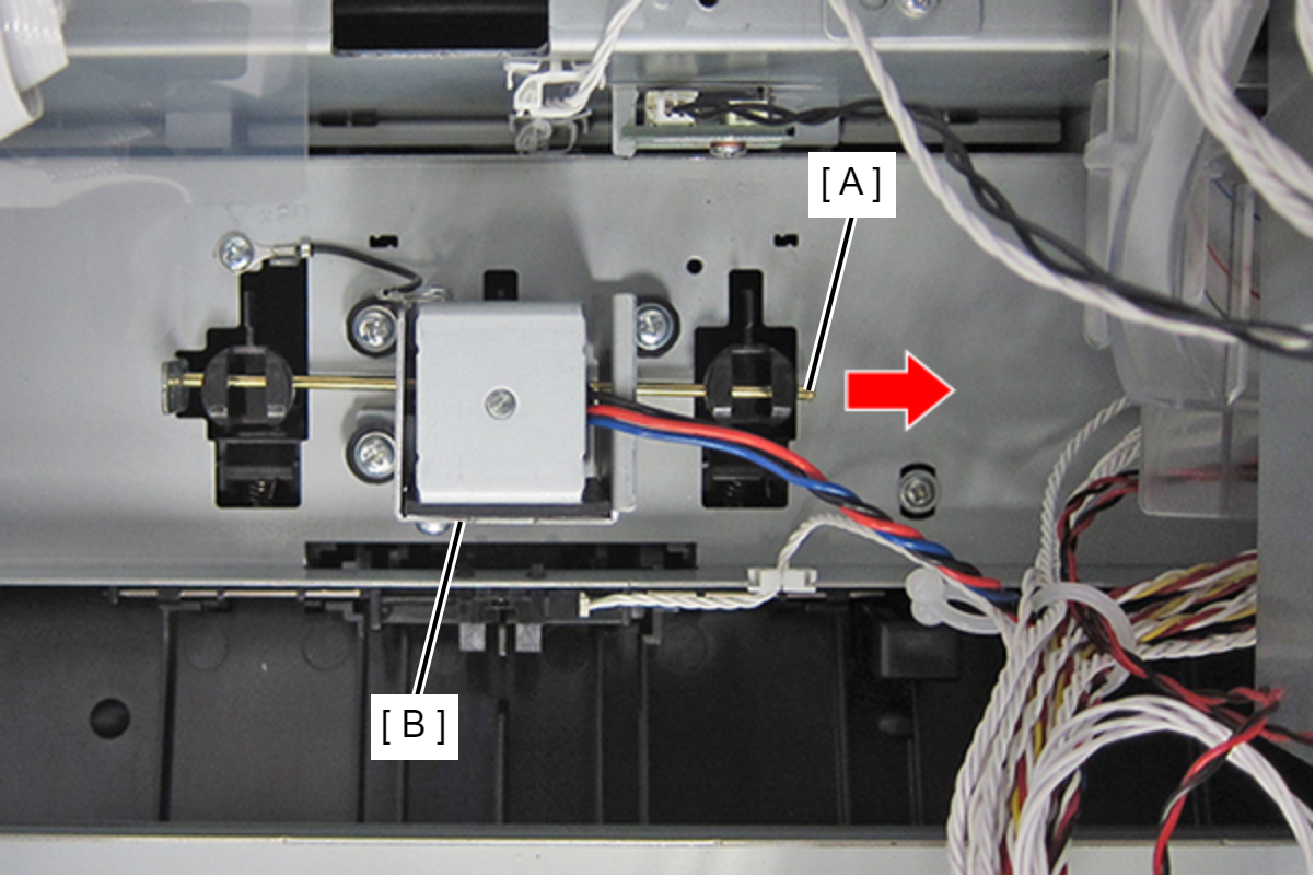 Assembly / 組み立て
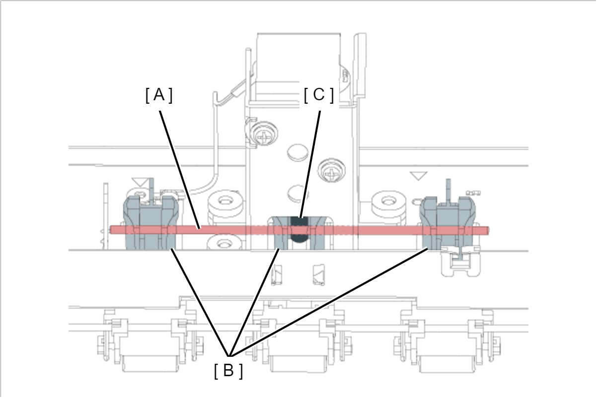
Mount the Nip Release Shaft (A) by passing it through the three holes in the Nip Release Holder (B) and the hole in the plunger (C).