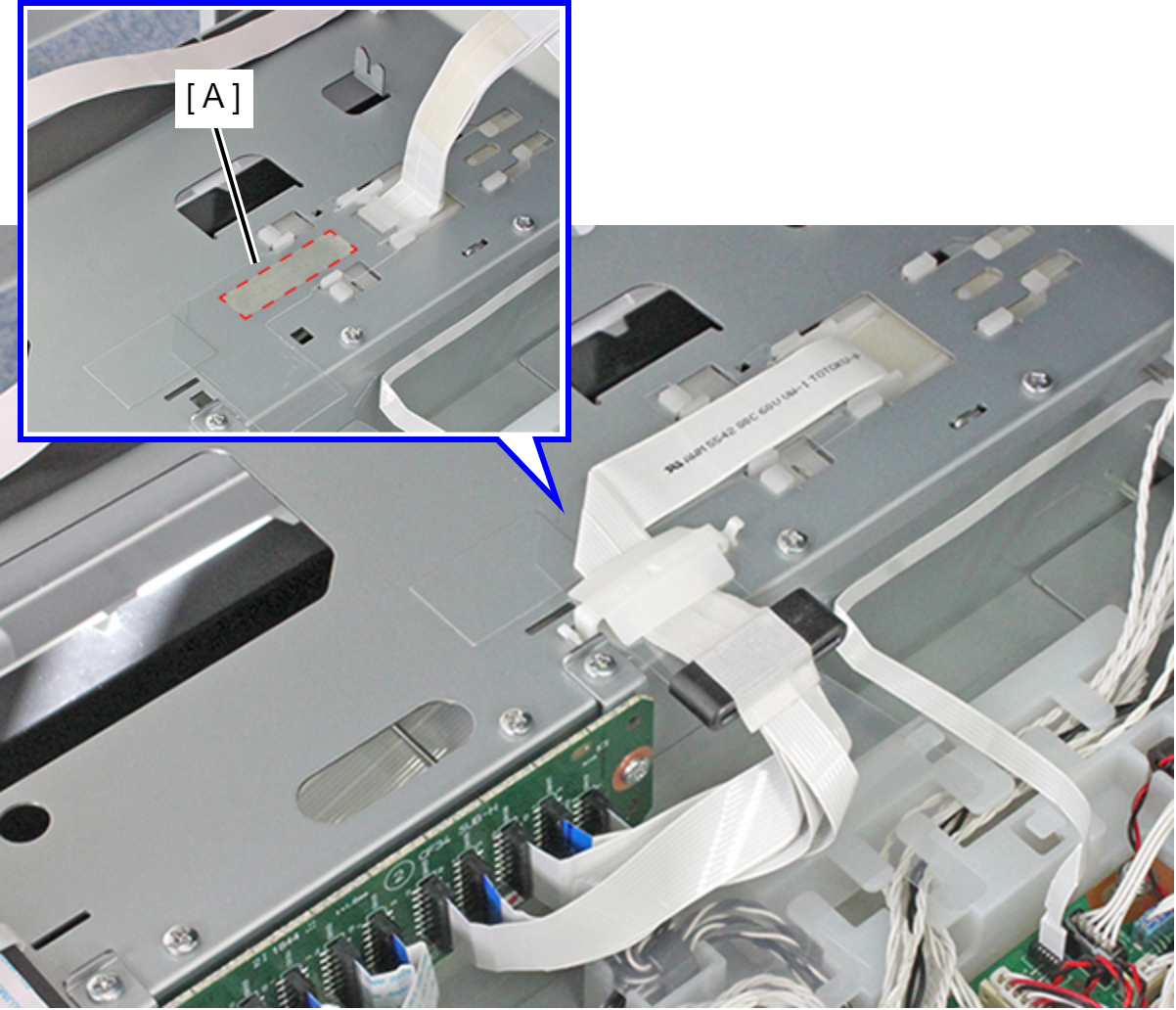
Head FFC Protection Sheet
- Remove the two screws.
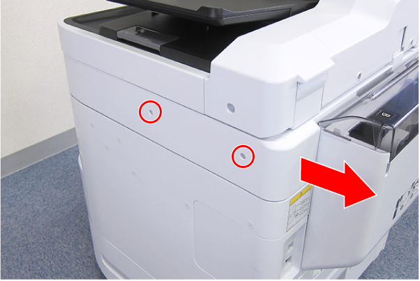
 : C.B.S-TITE-SCREW-3x8-F.ZN-3C
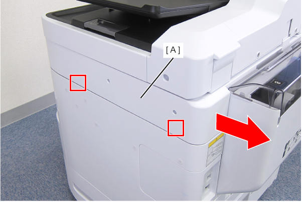
- Disengage the two hooks by sliding the Right SC Cover (A) toward the rear of the product, then remove it.
- Remove the screw.
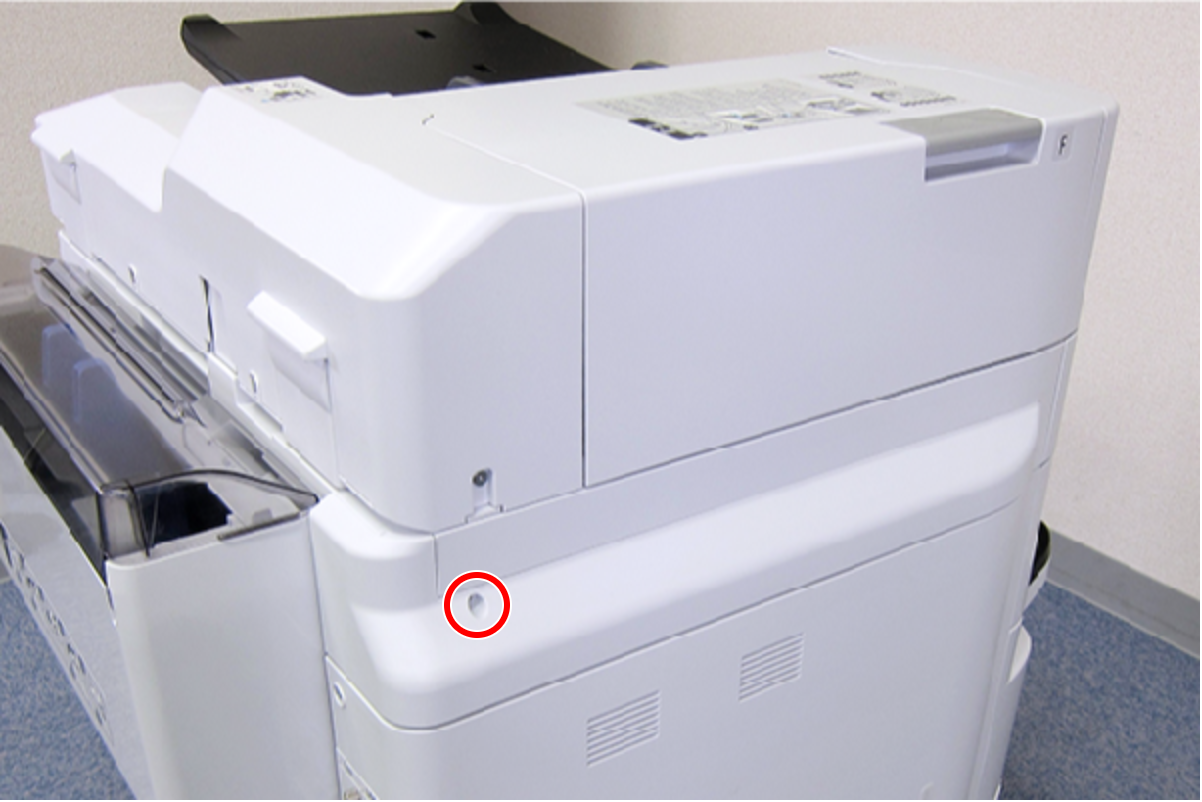
- : C.B.S-TITE-SCREW-3x8-F.ZN-3C
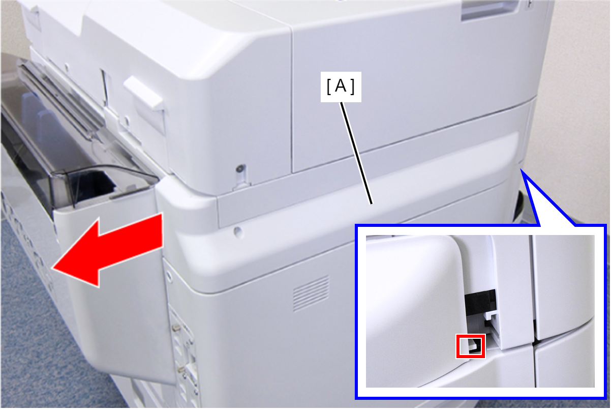
- Slide the Left SC Cover (A) toward the rear of the product to disengage the tab.
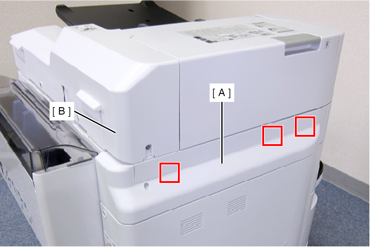
- Disengage the three tabs by inserting a flathead screwdriver into the gap between the Left SC Cover (A) and the ADF Unit (B), and then remove the Left SC Cover (A).
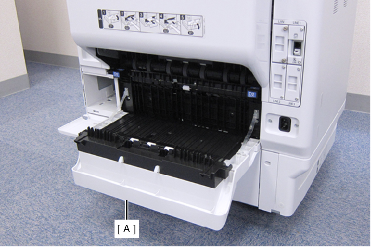
- Open the Duplex Print Cover (A).
- Remove the two screws, then remove the Connector Cover (A).
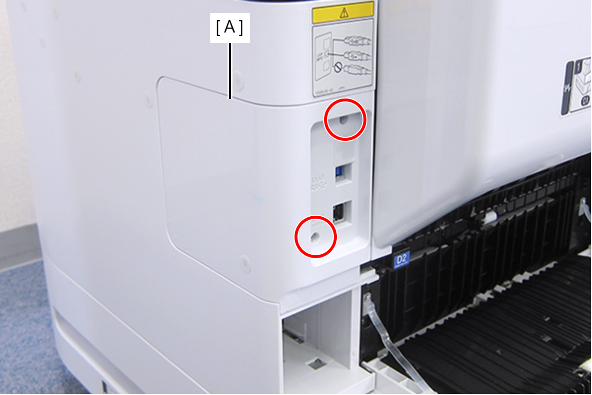
- : C.B.S-TITE-SCREW-3x8-F.ZN-3C
- Remove the two screws, then remove the Right Housing Assy (A) toward the rear of the product.
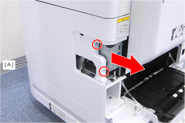
- : C.B.S-TITE-SCREW-3x8-F.ZN-3C
- Remove the two screws.
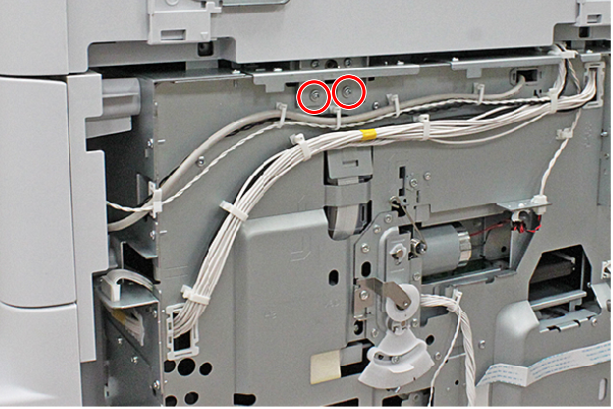
- : C.C.S-TITE-3x6-F.ZN-3C
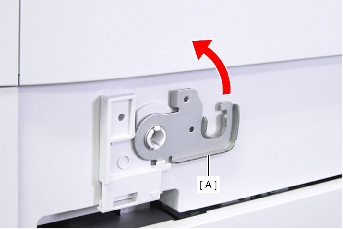
- Raise the ADF Stopper (A) to lock the ADF Unit.
- Secure the ADF Stopper with one of the screws you removed at step 1.
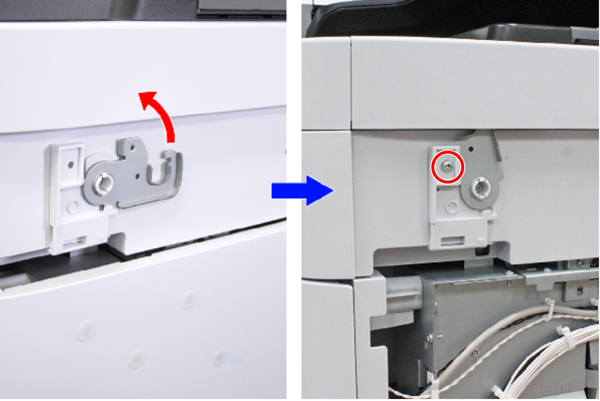
- : C.C.S-TITE-3x6-F.ZN-3C
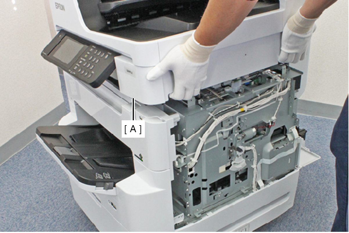
- Hold the ADF/SCN Unit (A) with both hands as shown above, and open the ADF/SCN Unit (A).
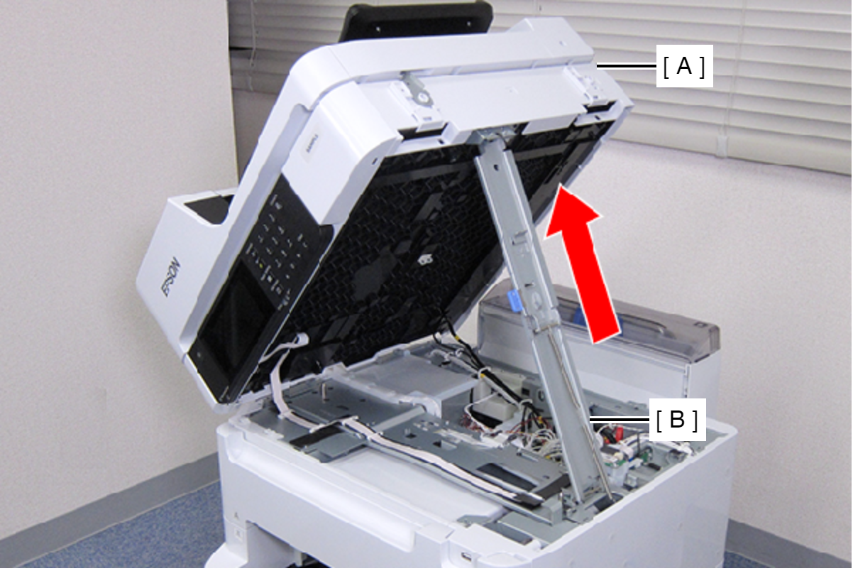
- Open the ADF/SCN Unit (A) and extend the support stand (B) as far as it goes, then support theADF/SCN Unit (A) with the support stand.
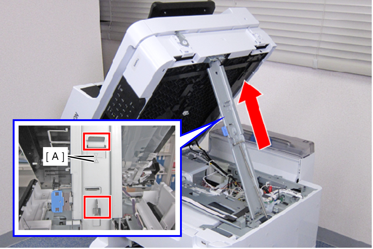
 Caution / 注意
Make sure that the extended support stand is fixed with the two hooks, and the two triangle marks face to each other.
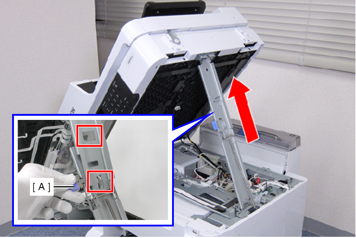
 Check Point / チェックポイント
When closing the ADF/SCN Unit, hold down the switch on the support stand and raise the ADF/SCN Unit in the direction of the arrow to disengage the two hooks, then fold the support stand.
- Remove the Stacker Assy (A).
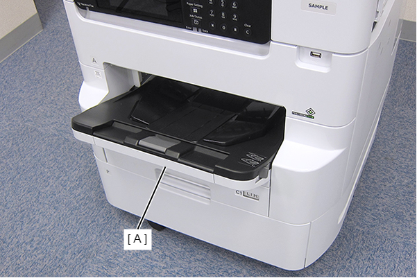
- Open the Front Cover Assy (A).
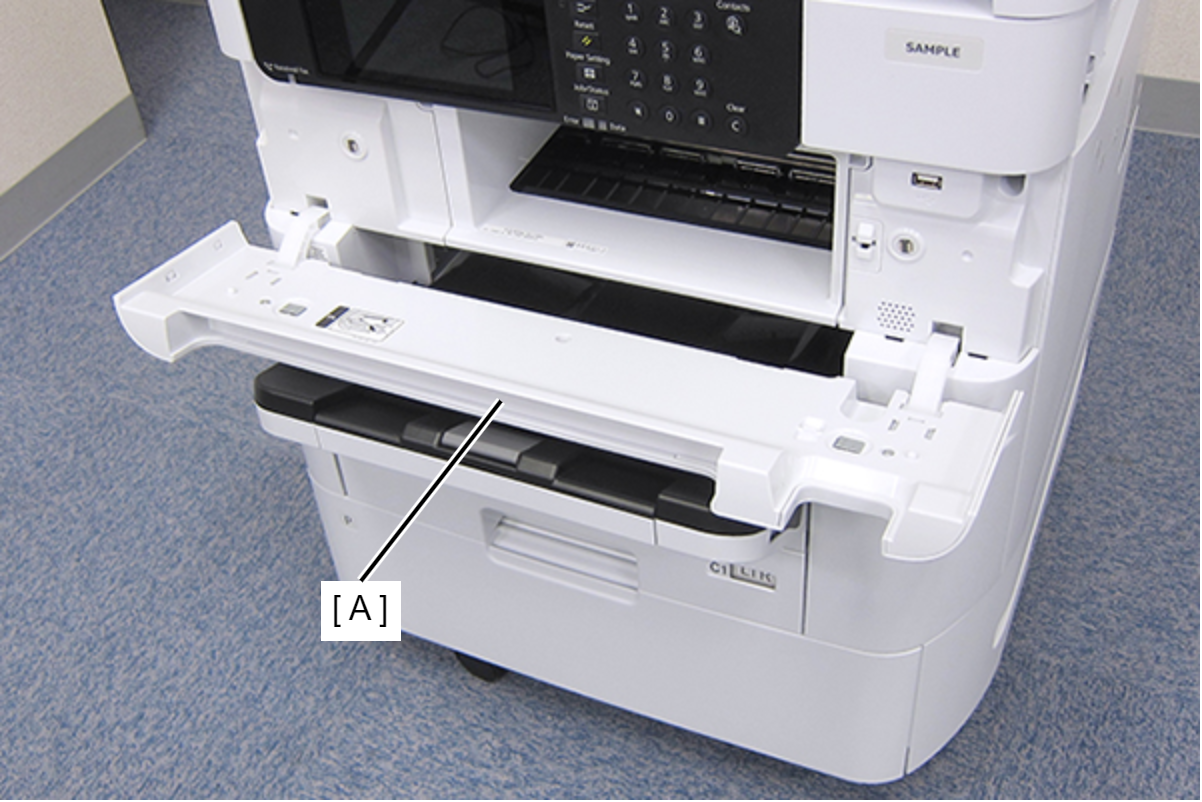
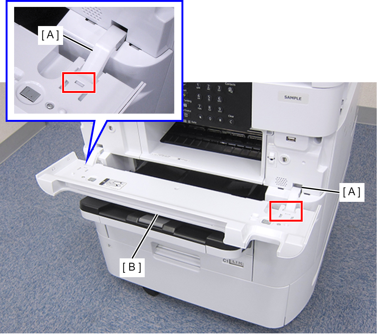
- While pressing the two hooks of the hinge (A), remove the Front Cover Assy (A) frontward.
- Remove the four screws, then remove the Front Inner Housing Center (A) frontward.
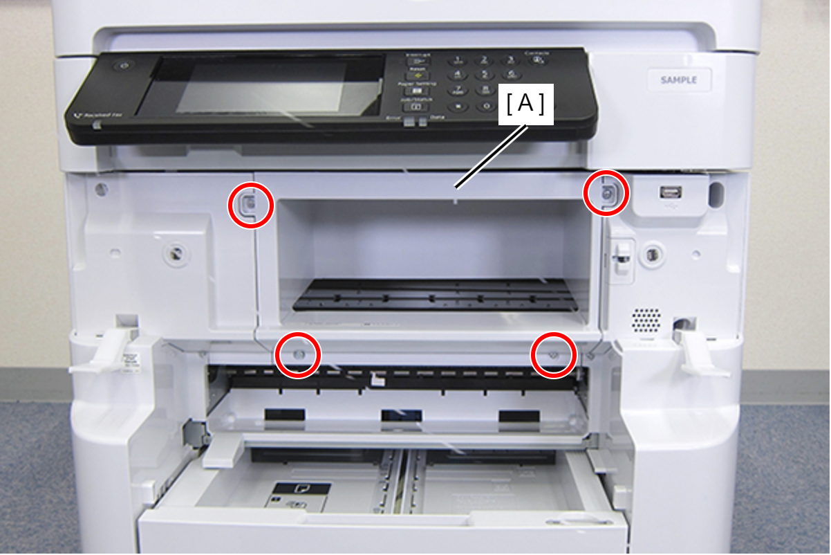
- : C.B.S-TITE-SCREW-3x8-F.ZN-3C
- Move the CR Unit (A) to the print head replacement position.
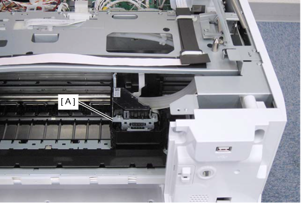
- Remove the thee screws that secure the joint portion of ink tube (A).
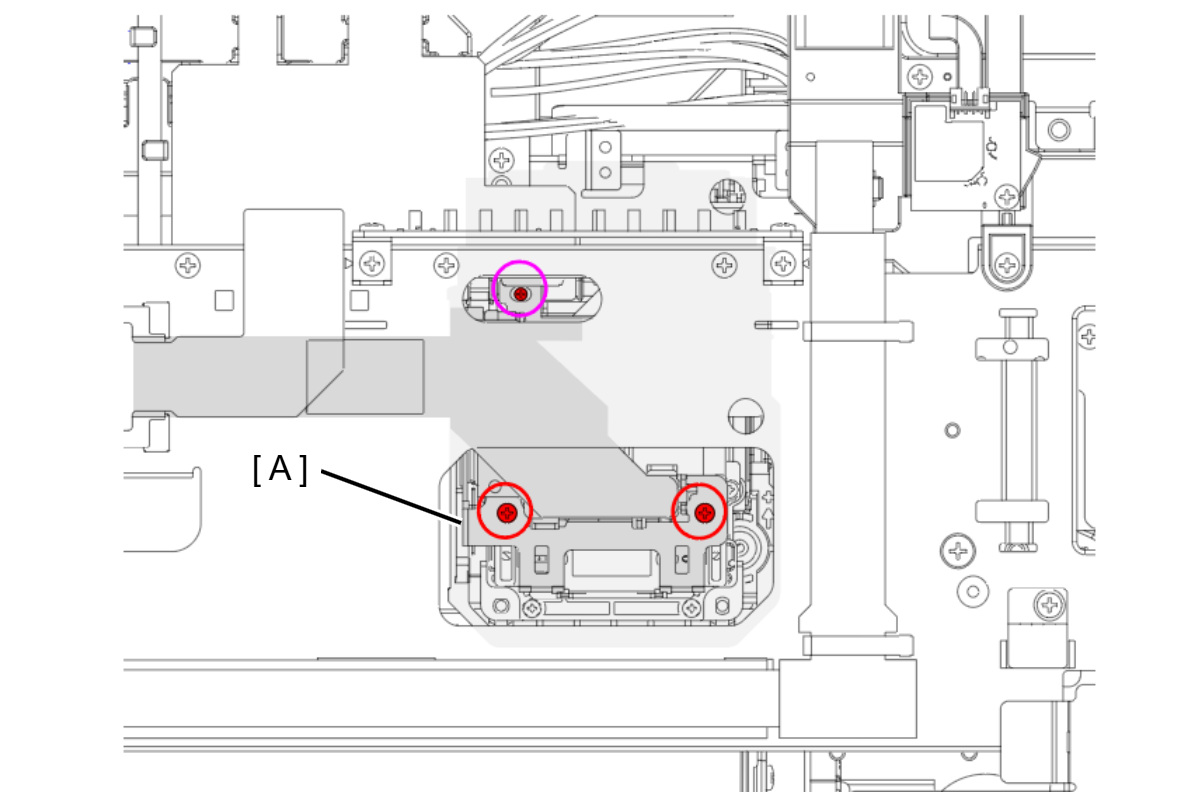
- : C.B.S2-3x12-F.ZN-3C
 : C.B.P-TITE-SCREW-2.5x10-F.ZN-3C
- Remove the ink tube joint portion (A).
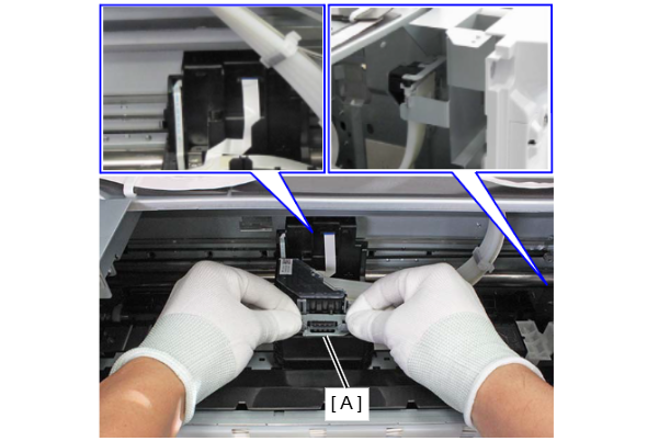 Caution / 注意
To prevent the ink tube joint portion from being damaged, hold the frame of the ink tube joint portion with both hands and remove the joint portion straight upward.
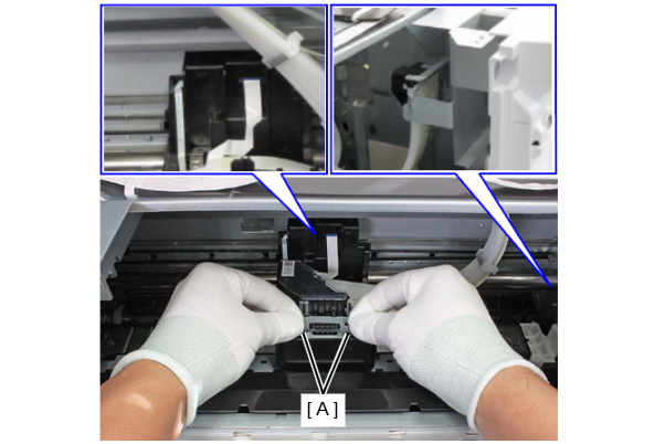
- Hook the ink tube connector (A) on the hooks (B) on the frame.
- Disconnect the FFC (B) from the connector (A) of the CR encoder sensor.
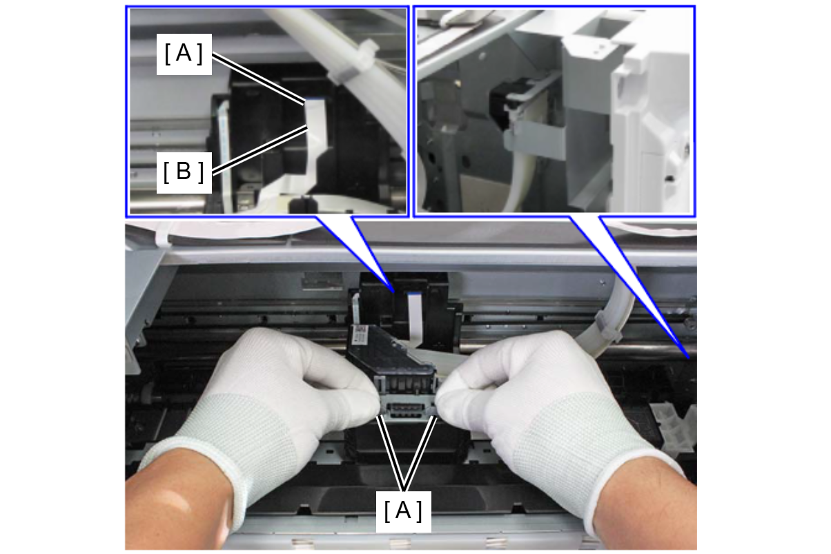
- Remove the three screws, then remove the Print Head (A).
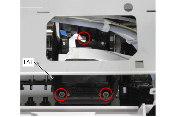
- : SCREW,MOUNT,HEAD,ASSY
 Assembly / 組み立て
- Follow the procedure below to install the Print Head.
- Connect the four Head FFCs (A) to the connector of the Print Head.
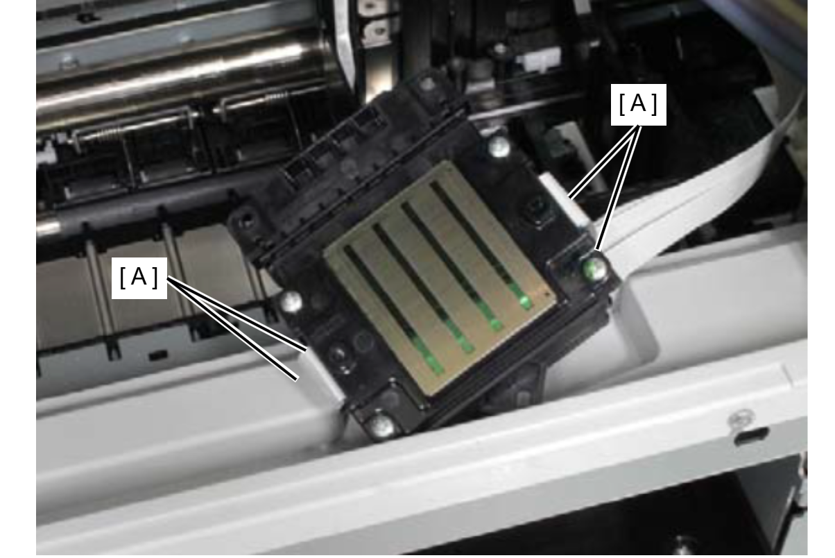
- Press the Print Head (A) in the direction of the arrow in order, set it to the CR Unit (B), and fix it with the three screws.
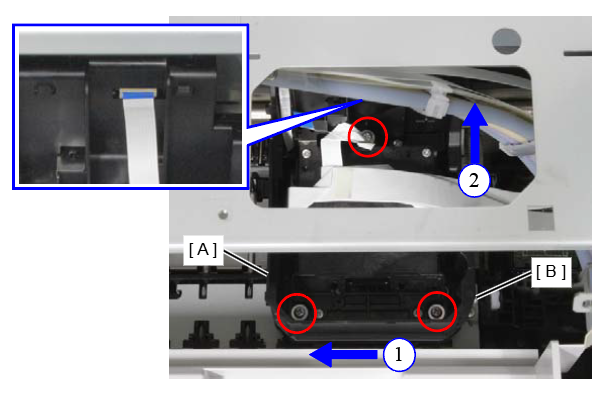
- Connect the FFC (A) to the connector of the CR encoder sensor.
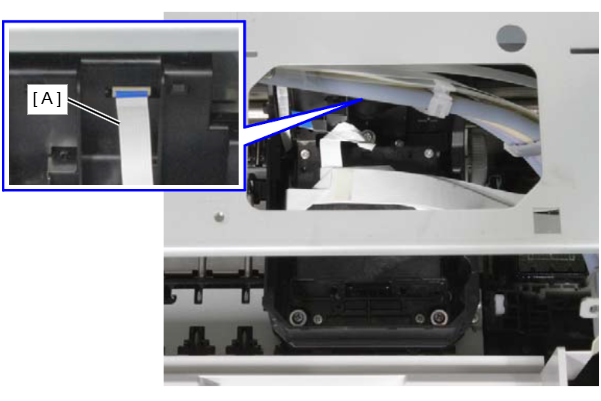
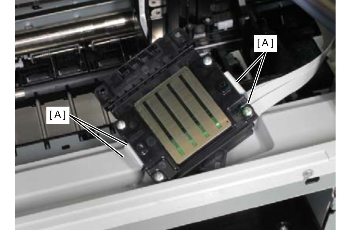
- Disconnect the four Head FFCs (A) from the connector of the Print Head.
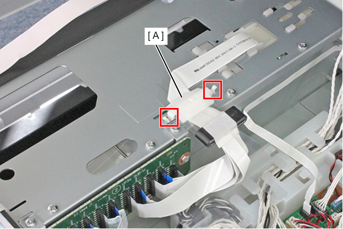
- Release the two hooks and remove the FFC Clamp (A).
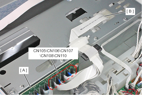
- Remove the Head FFC Assy (B) from the connectors (CN105, CN106, CN107, CN108, CN110) of the Head Relay Board (A).
- Peel away the double-sided tape and remove the Head FFC Protection Sheet (A).