
Ink Supply Tube Assy
 Adjustment / 調整 Adjustment / 調整 |
When replacing/removing this part, refer to the following pages and make sure to perform the specified operations including the required adjustments. |
- Remove the two screws.
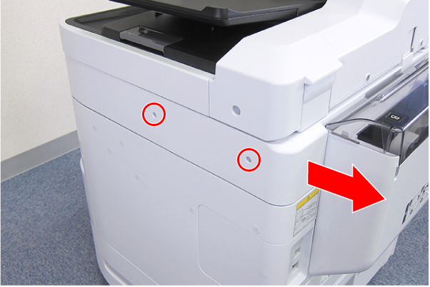
 : C.B.S-TITE-SCREW-3x8-F.ZN-3C
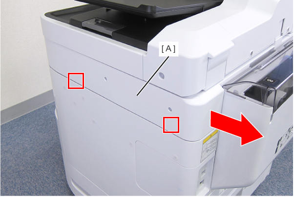
- Disengage the two hooks by sliding the Right SC Cover (A) toward the rear of the product, then remove it.
- Remove the screw.
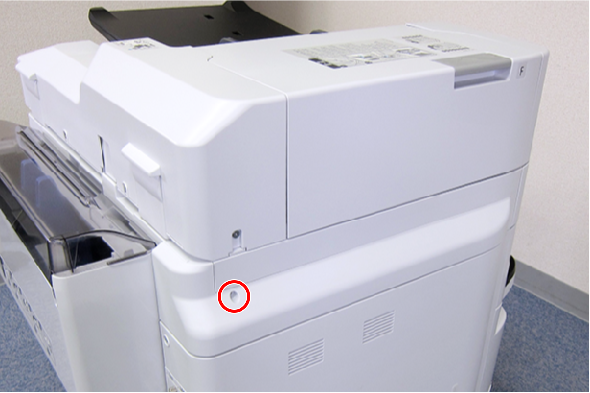
- : C.B.S-TITE-SCREW-3x8-F.ZN-3C
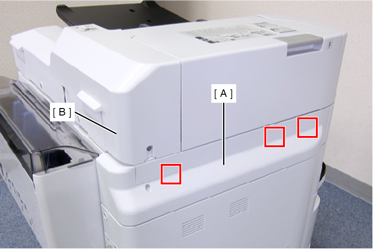
- Slide the Left SC Cover (A) toward the rear of the product to disengage the tab.
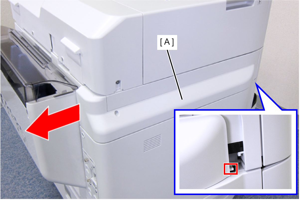
- Disengage the three tabs by inserting a flathead screwdriver into the gap between the Left SC Cover (A) and the ADF Unit (B), and then remove the Left SC Cover (A).
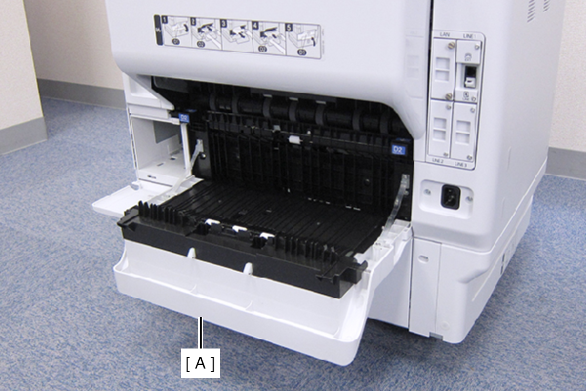
- Open the Duplex Print Cover (A).
- Remove the two screws, then remove the Connector Cover (A).
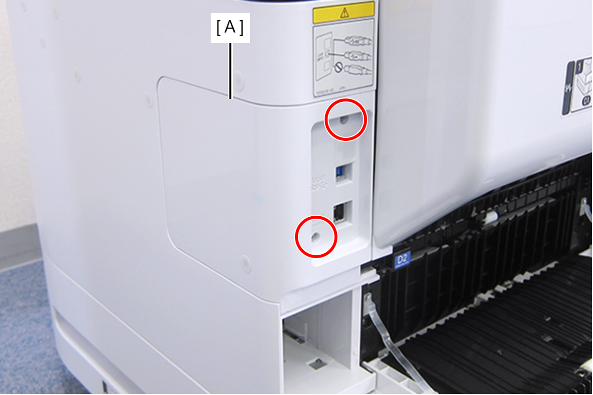
- : C.B.S-TITE-SCREW-3x8-F.ZN-3C
- Remove the two screws, then remove the Right Housing Assy (A) toward the rear of the product.
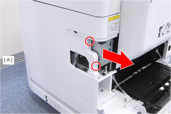
- : C.B.S-TITE-SCREW-3x8-F.ZN-3C
- Remove the two screws.
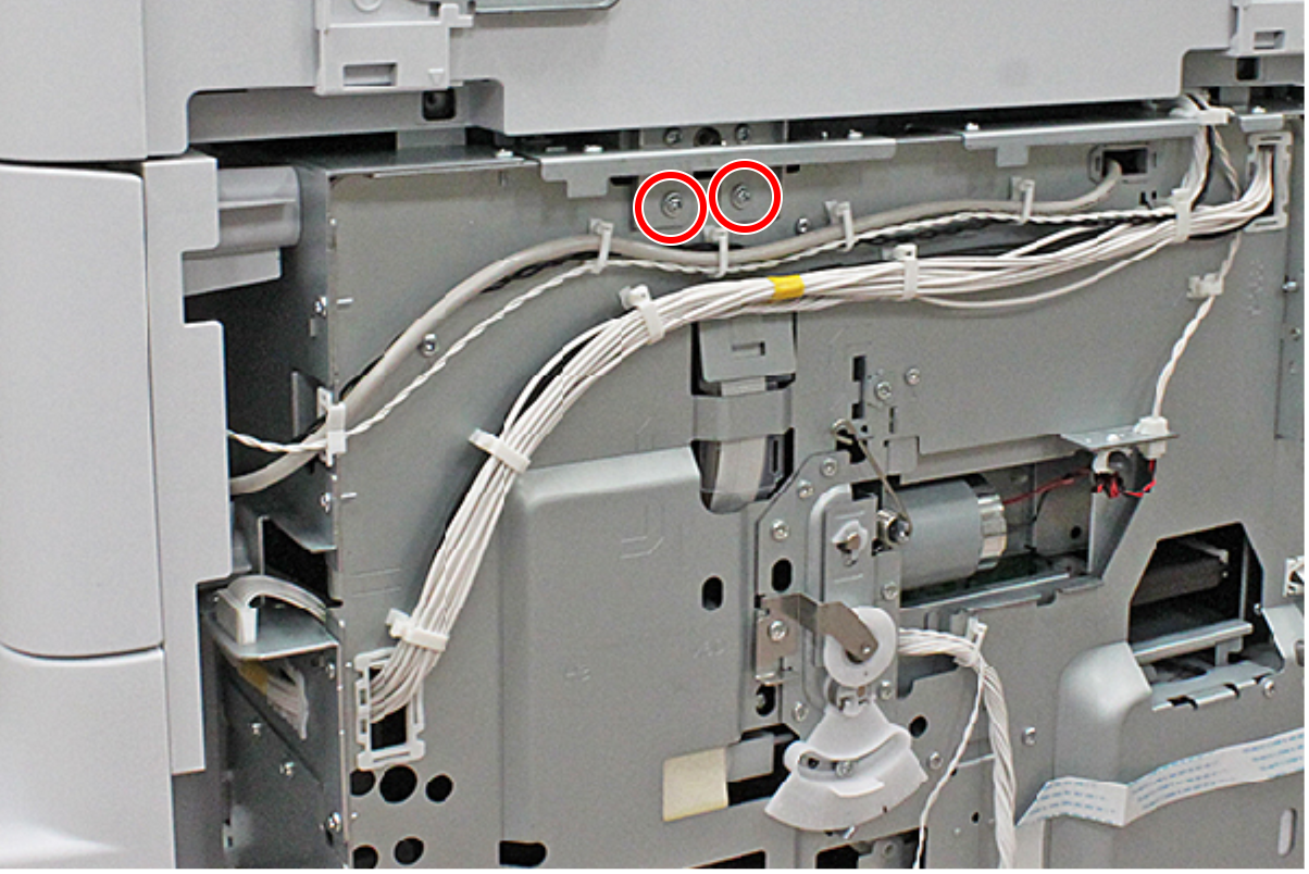
- : C.C.S-TITE-3x6-F.ZN-3C
- Raise the ADF Stopper (A) to lock the ADF Unit.
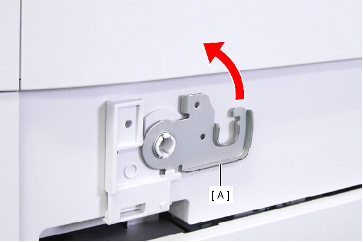
- Secure the ADF Stopper with one of the screws you removed at step 1.
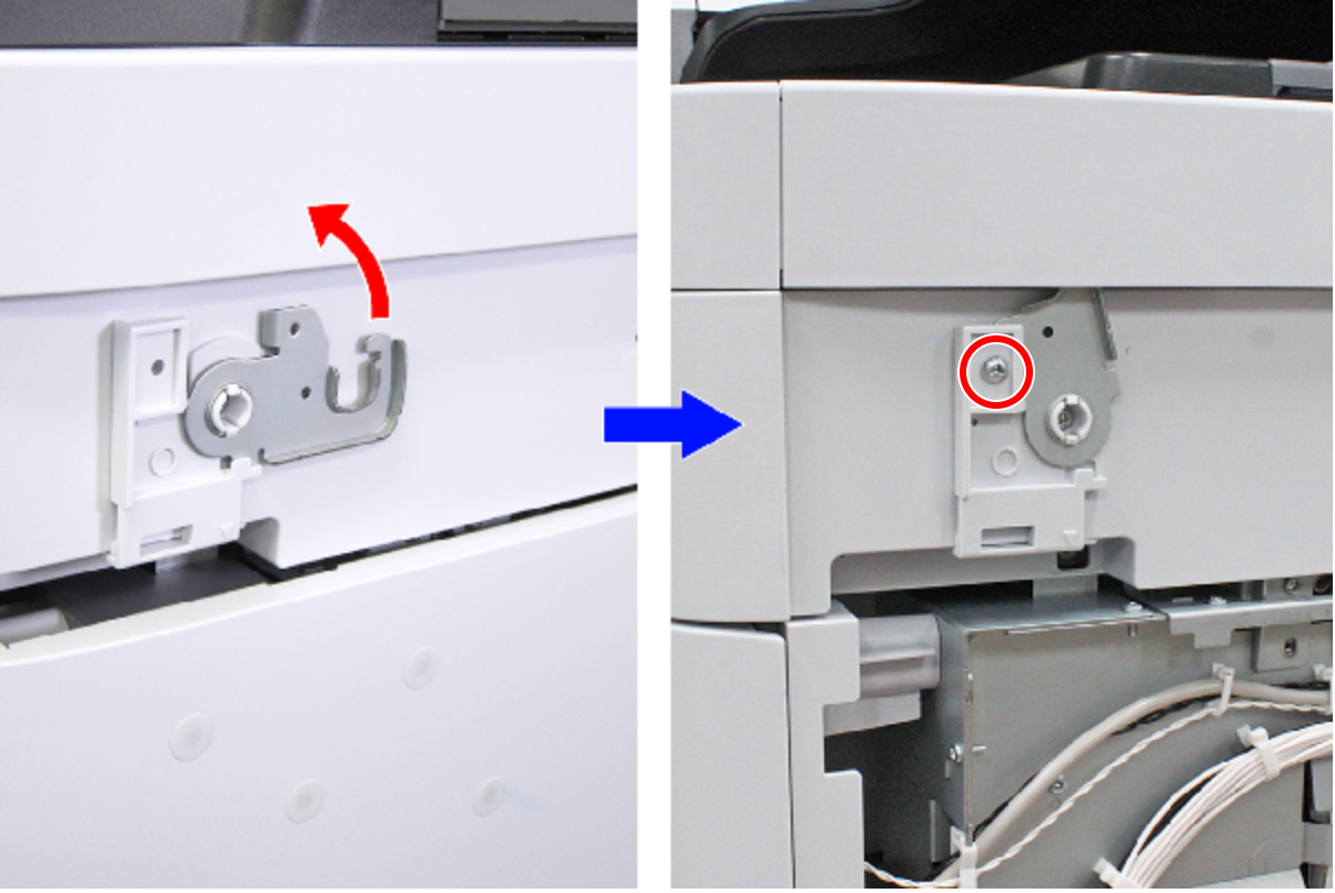
- : C.C.S-TITE-3x6-F.ZN-3C
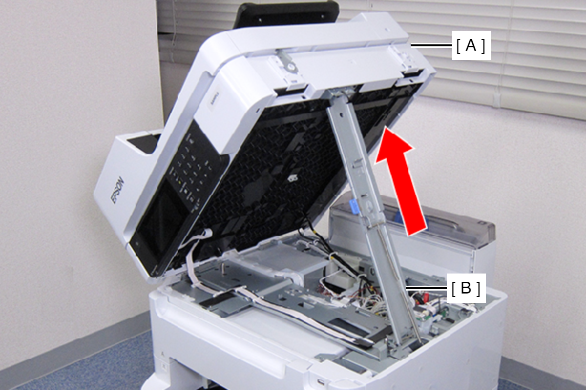
- Hold the ADF/SCN Unit (A) with both hands as shown above, and open the ADF/SCN Unit (A).
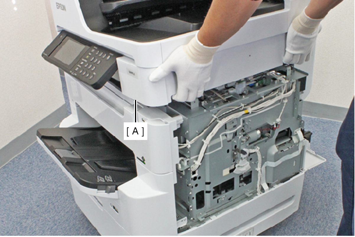
- Open the ADF/SCN Unit (A) and extend the support stand (B) as far as it goes, then support theADF/SCN Unit (A) with the support stand.
 Caution / 注意
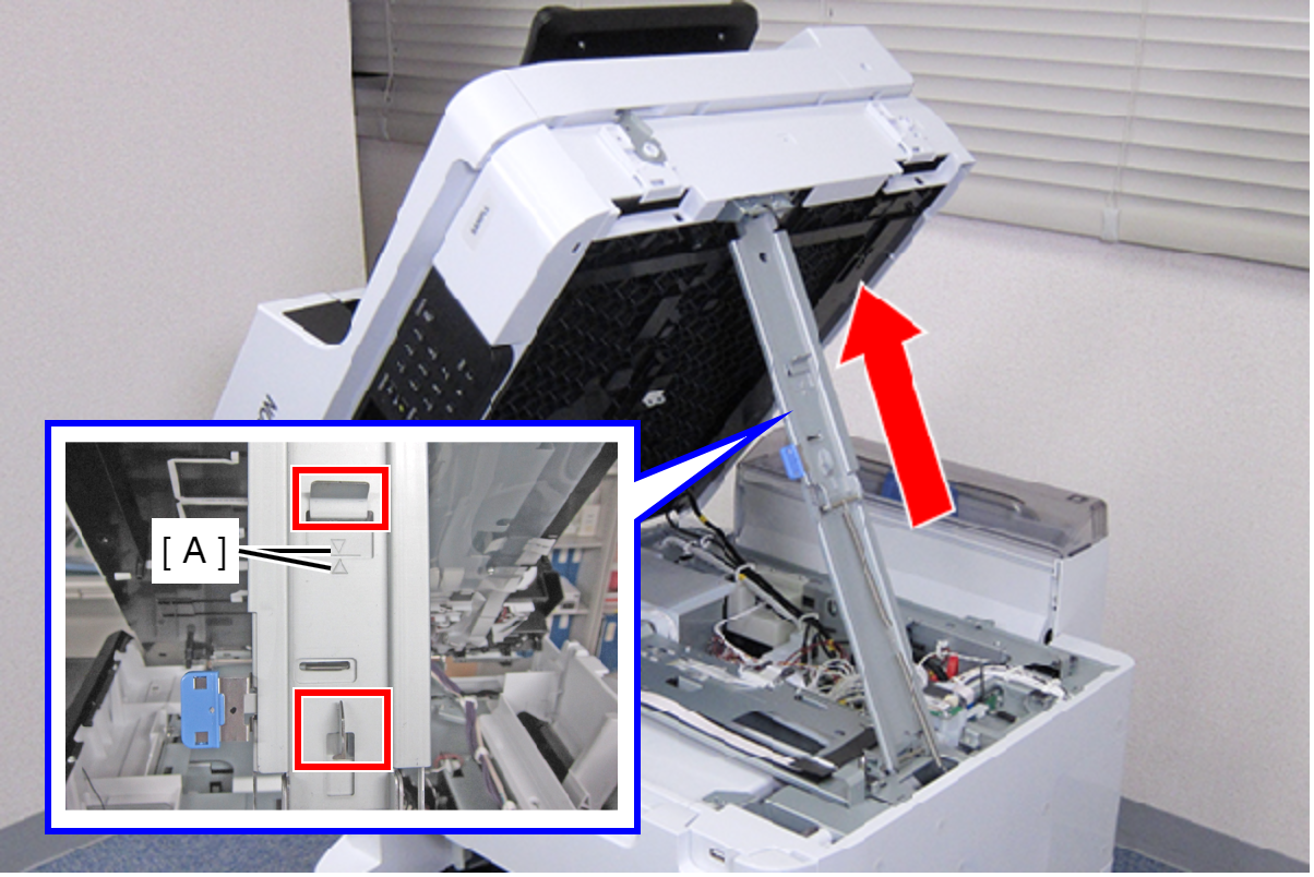
Make sure that the extended support stand is fixed with the two hooks, and the two triangle marks face to each other.
 Check Point / チェックポイント
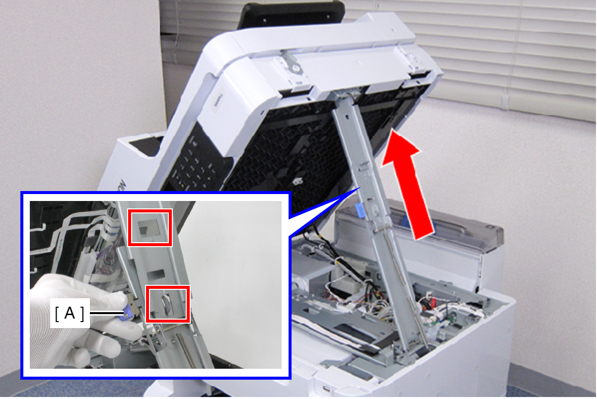
When closing the ADF/SCN Unit, hold down the switch on the support stand and raise the ADF/SCN Unit in the direction of the arrow to disengage the two hooks, then fold the support stand.
- Remove the three screws, then remove the Left Housing Assy (A) toward the rear of the product.
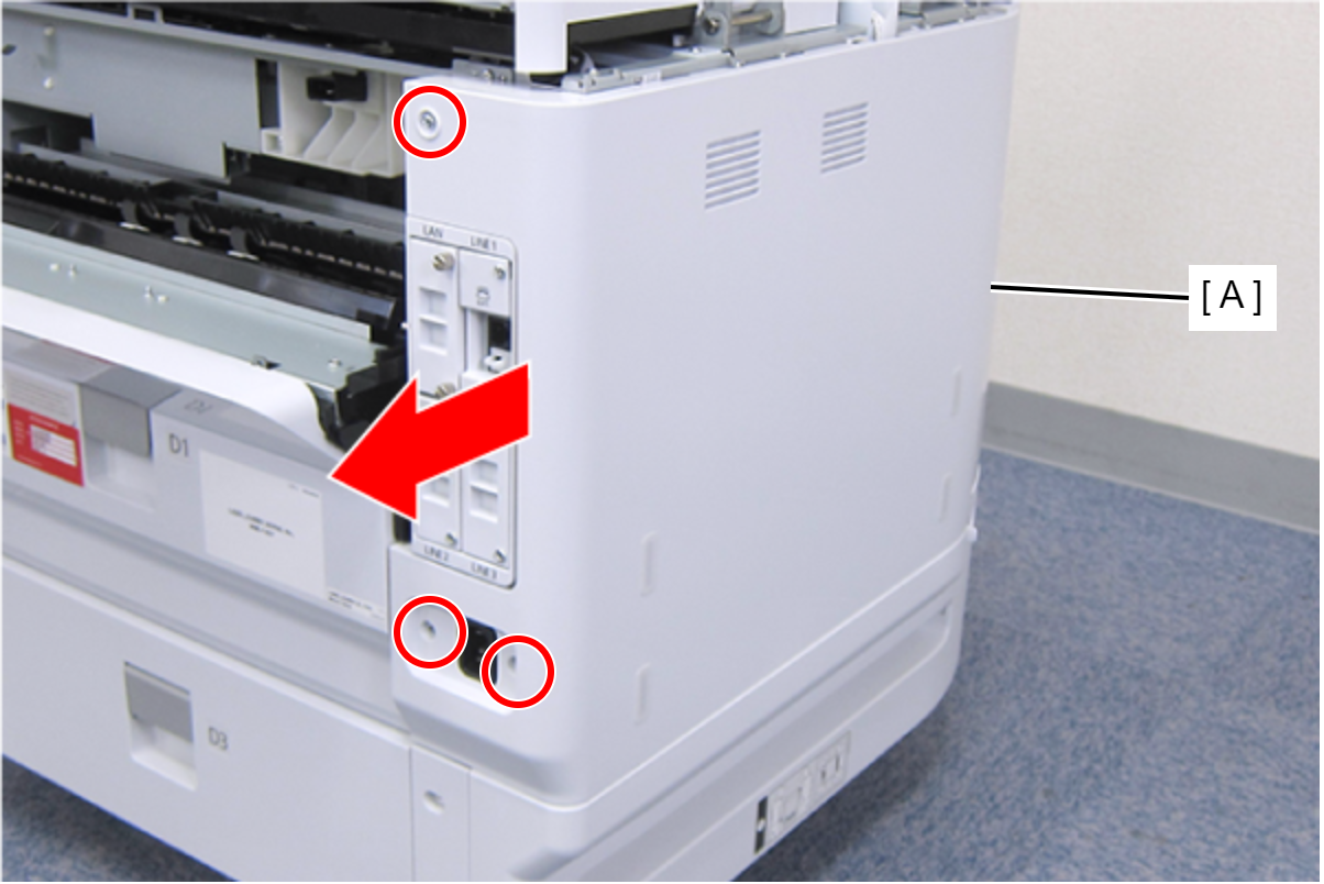
- : C.B.S-TITE-SCREW-3x8-F.ZN-3C
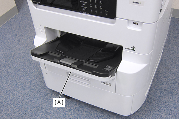
- Remove the Stacker Assy (A).
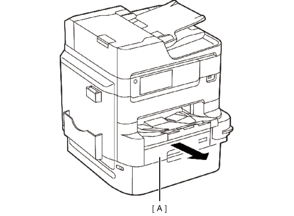
- Remove the Cassette Assy (A).
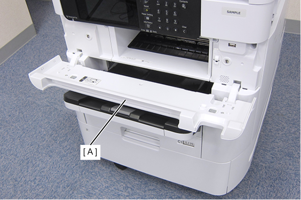
- Open the Front Cover Assy (A).
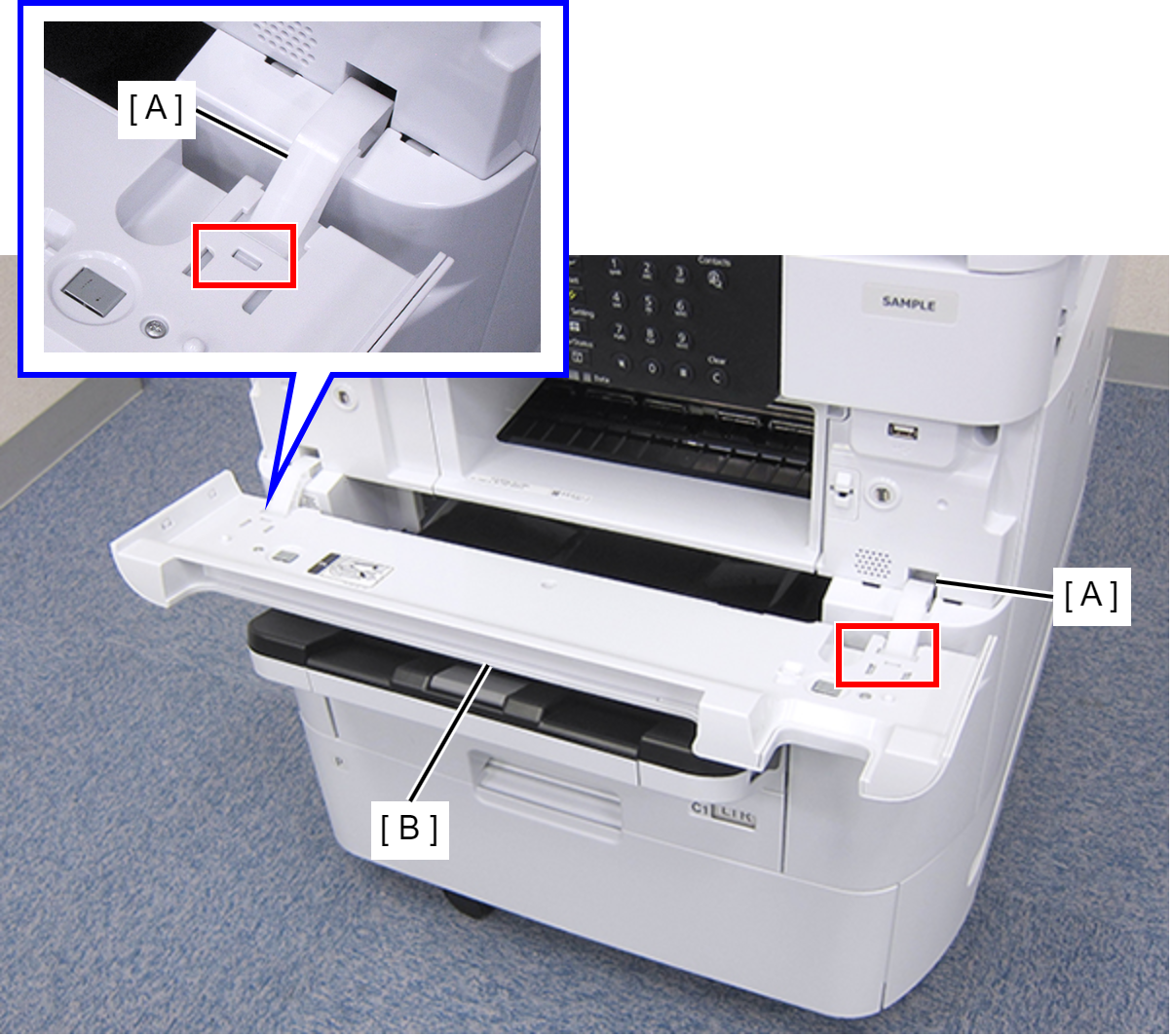
- While pressing the two hooks of the hinge (A), remove the Front Cover Assy (A) frontward.
- Remove the three screws fastening the Front Left Housing (A).
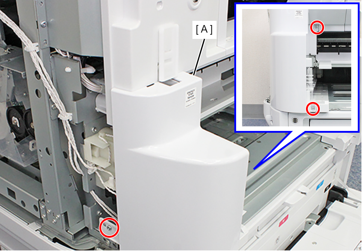
- : C.B.S-TITE-SCREW-3x8-F.ZN-3C
- Release the hook and remove the Front Left Housing (A).

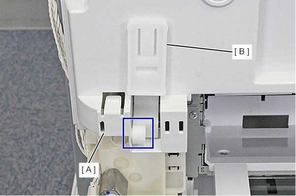
- Remove the Front Cover Hinge Left (B) from the Dowel on the Front Inner Housing Left (A).
- Remove the four screws, then remove the Front Inner Housing Center (A) frontward.
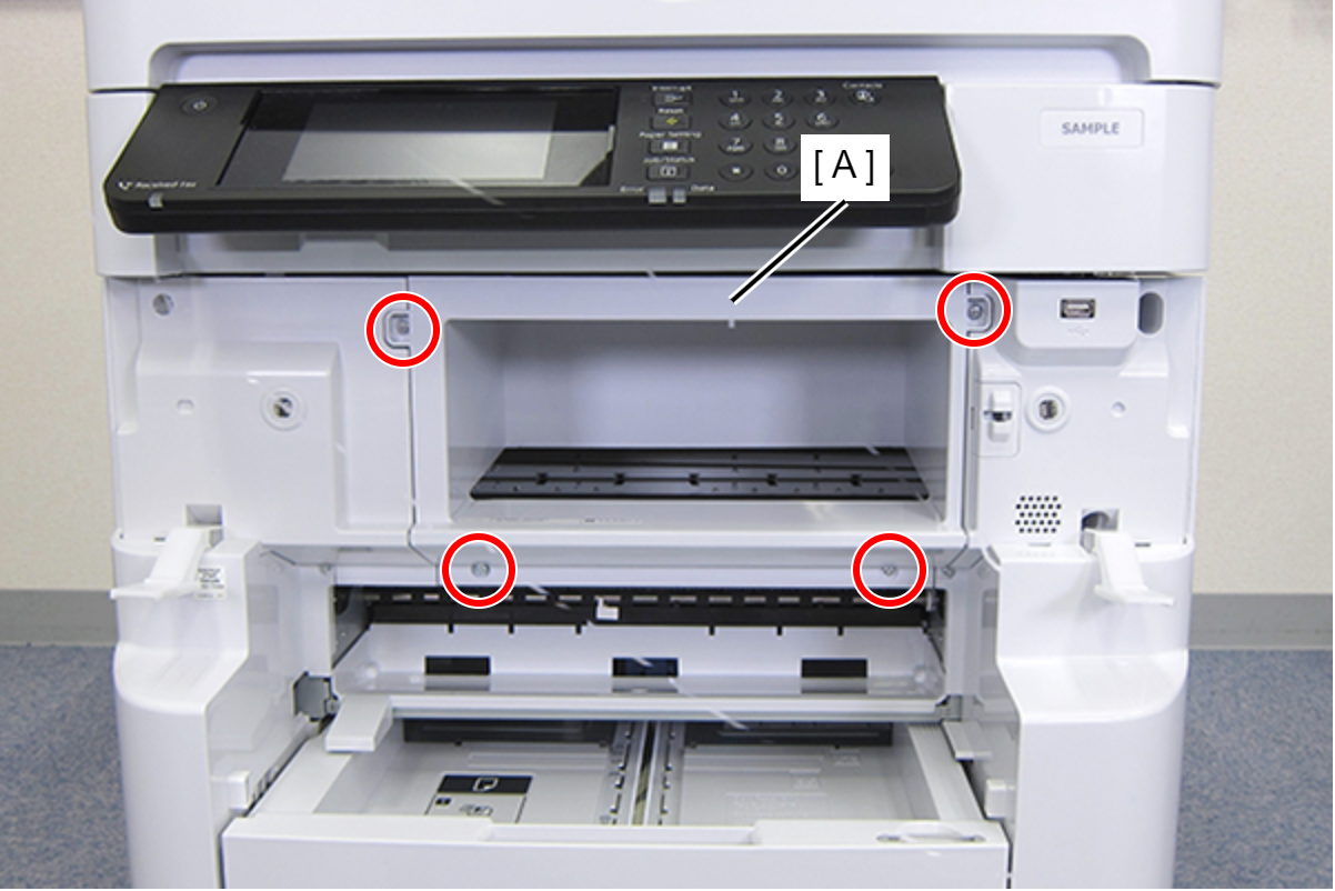
- : C.B.S-TITE-SCREW-3x8-F.ZN-3C
- Remove the two screws fastening the Front Inner Housing Left (A).
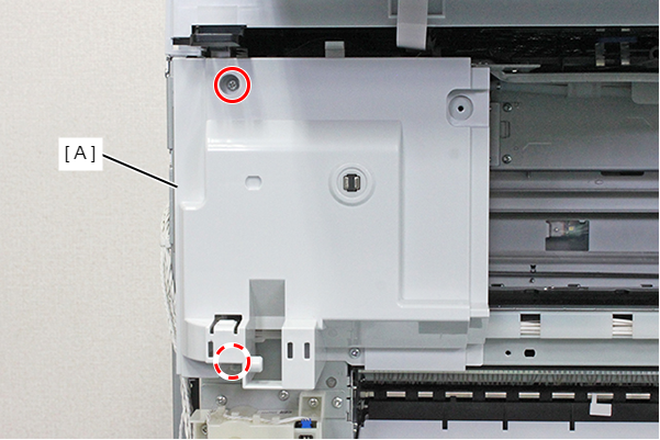
- : C.B.S-TITE-SCREW-3x8-F.ZN-3C
- Remove the Front Inner Housing Left (C) while releasing the place interfering (A) with the ADF/SCN Unit (A).
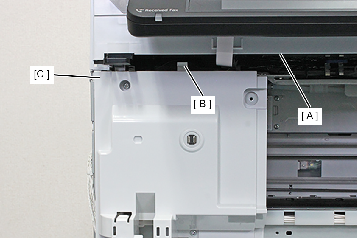
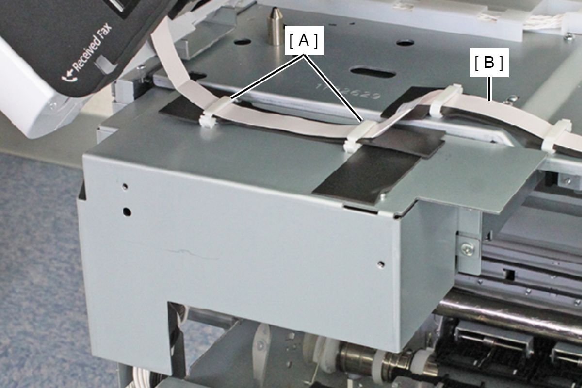
- Release the Panel FFC (B) from the two clamps (A).
- Remove the two screws and remove the Power Supply Unit Cover (A).
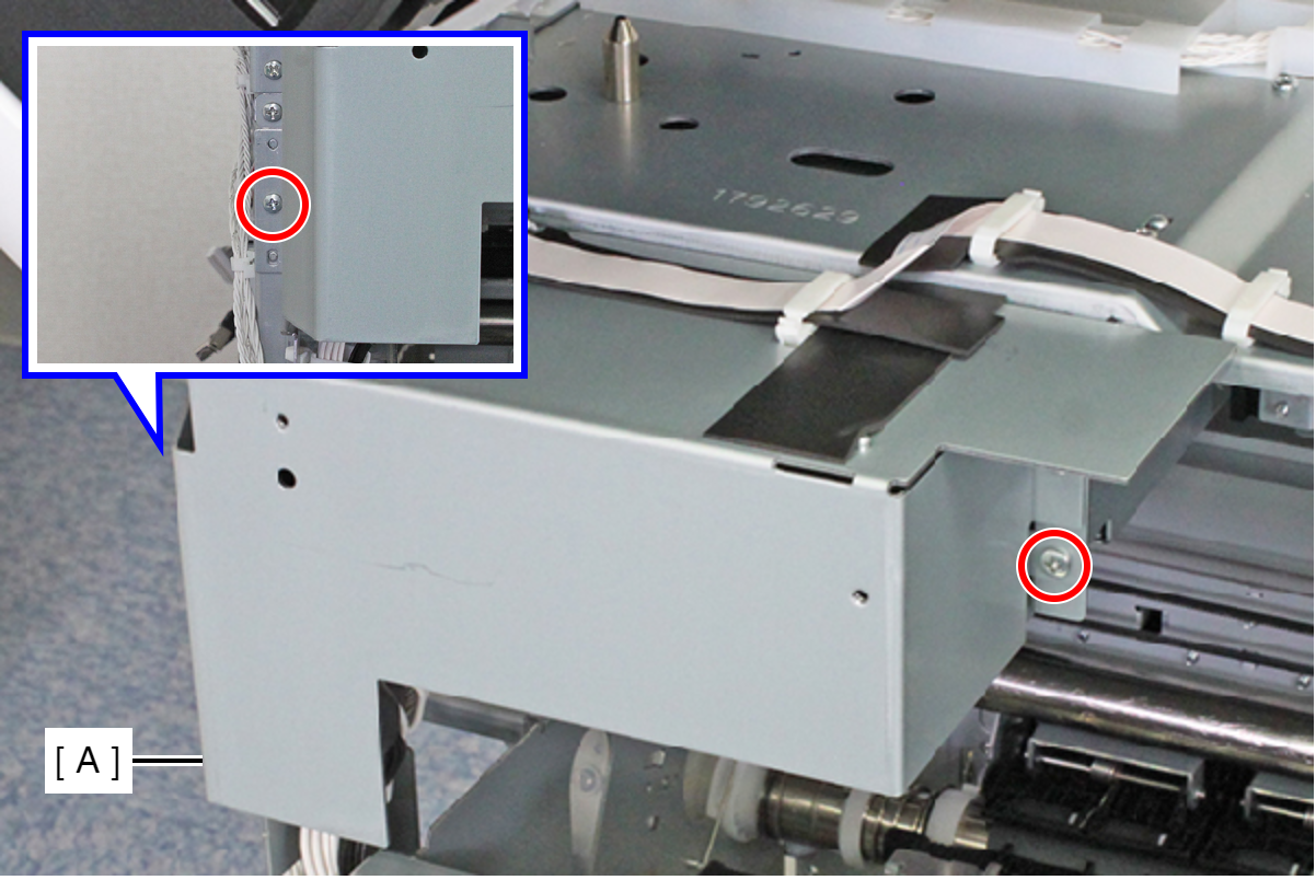
- : C.B.S-TITE-SCREW-3x8-F.ZN-3C
- Release the two cables from the two clamps (A).
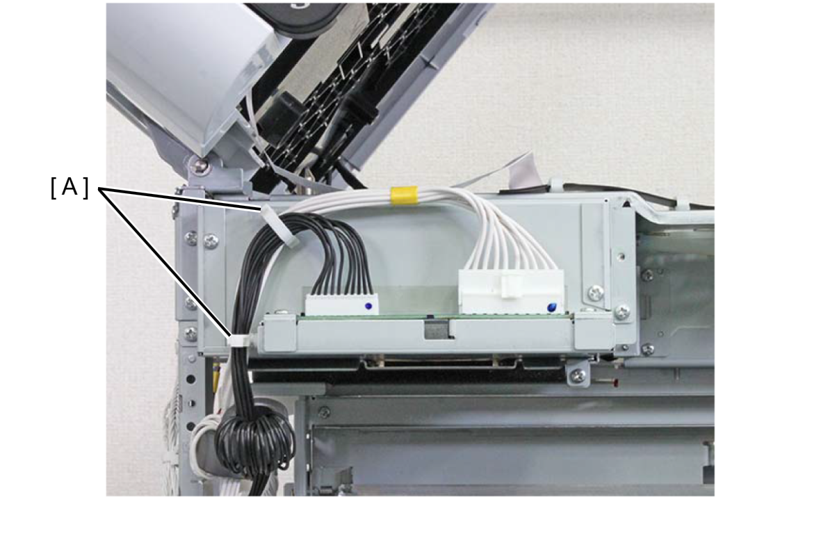
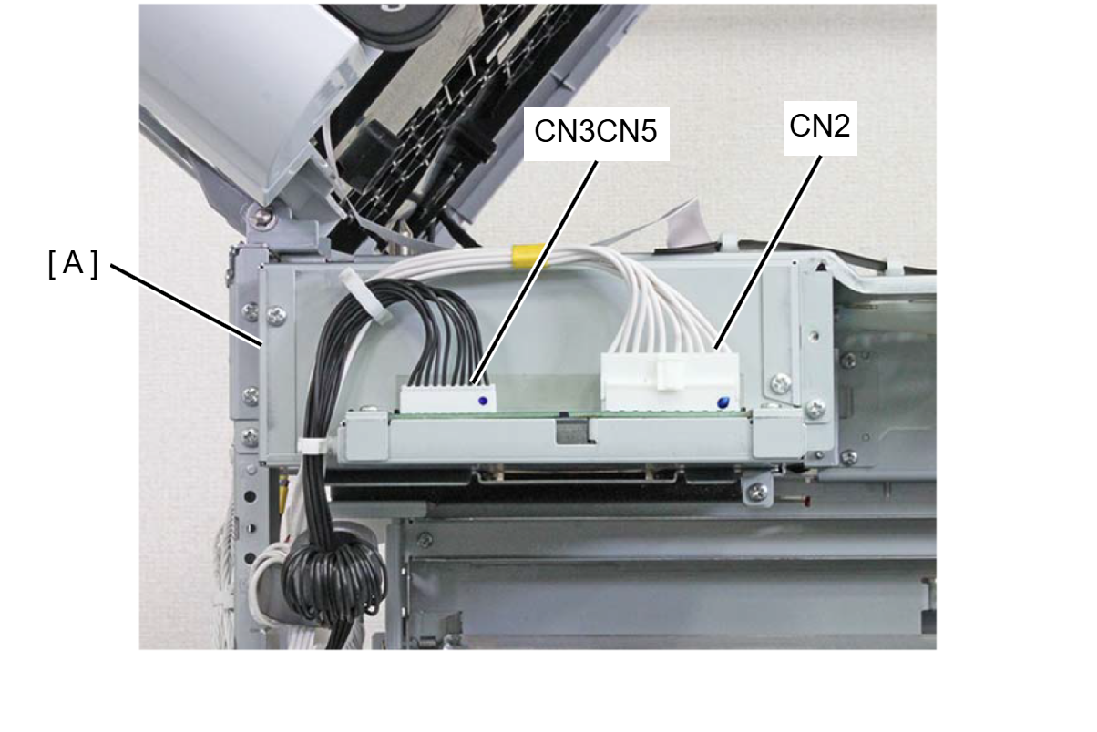
- Remove the cables from the connectors (CN2 (with hooks), CN3, CN5) of the Power Supply Unit.
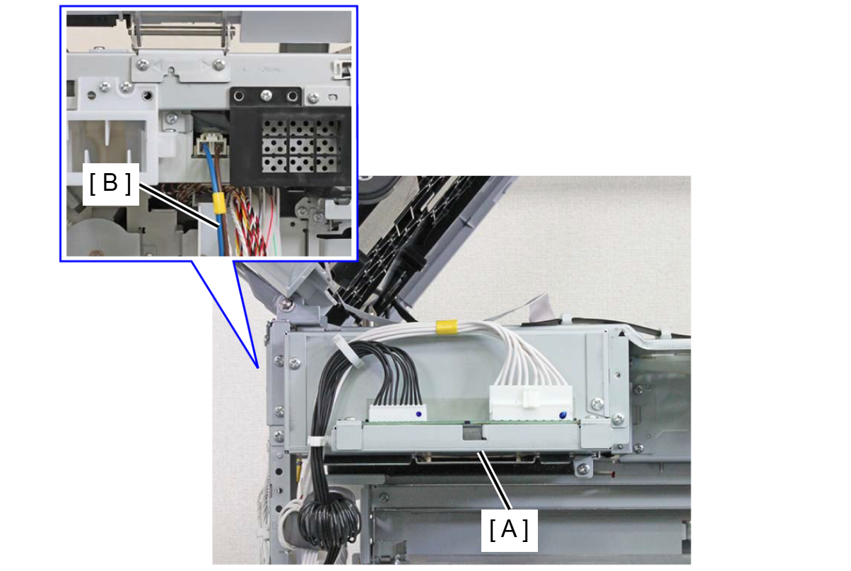
- Remove the Power Supply Unit Cable (B) from the Power Supply Unit (A) while releasing the hook.
- Remove the three screws and remove the Power Supply Unit (A).
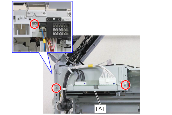
- : C.B.S-TITE-SCREW-3x8-F.ZN-3C
- Remove the screw, and remove the Heat Vent Cover (A).
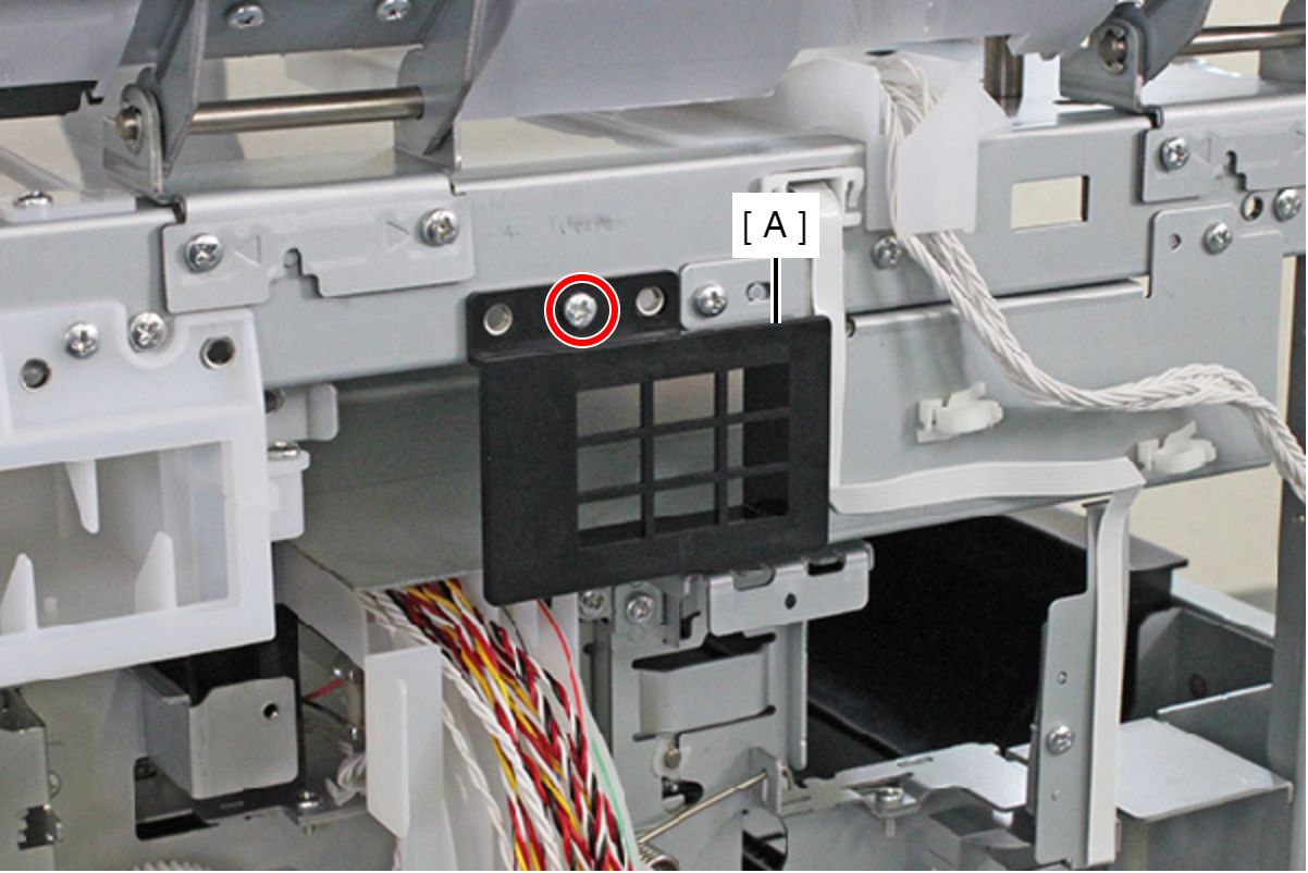
- : C.B.S-TITE-SCREW-3x8-F.ZN-3C
- Remove the hole from the screw feet (A) and pull out the folded portion (C) of the PF Scale Protection Material (B).
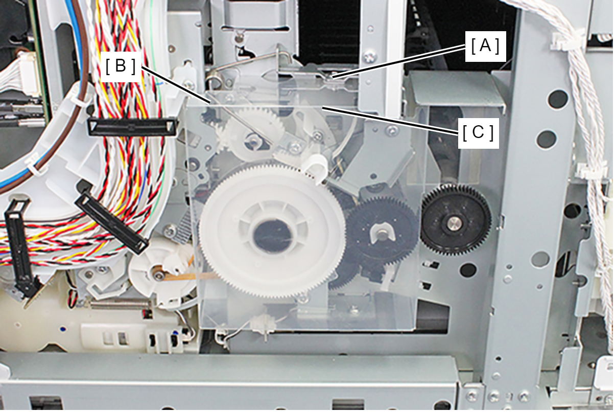
- Release the two hooks and remove the PF Scale Protection Material (A).
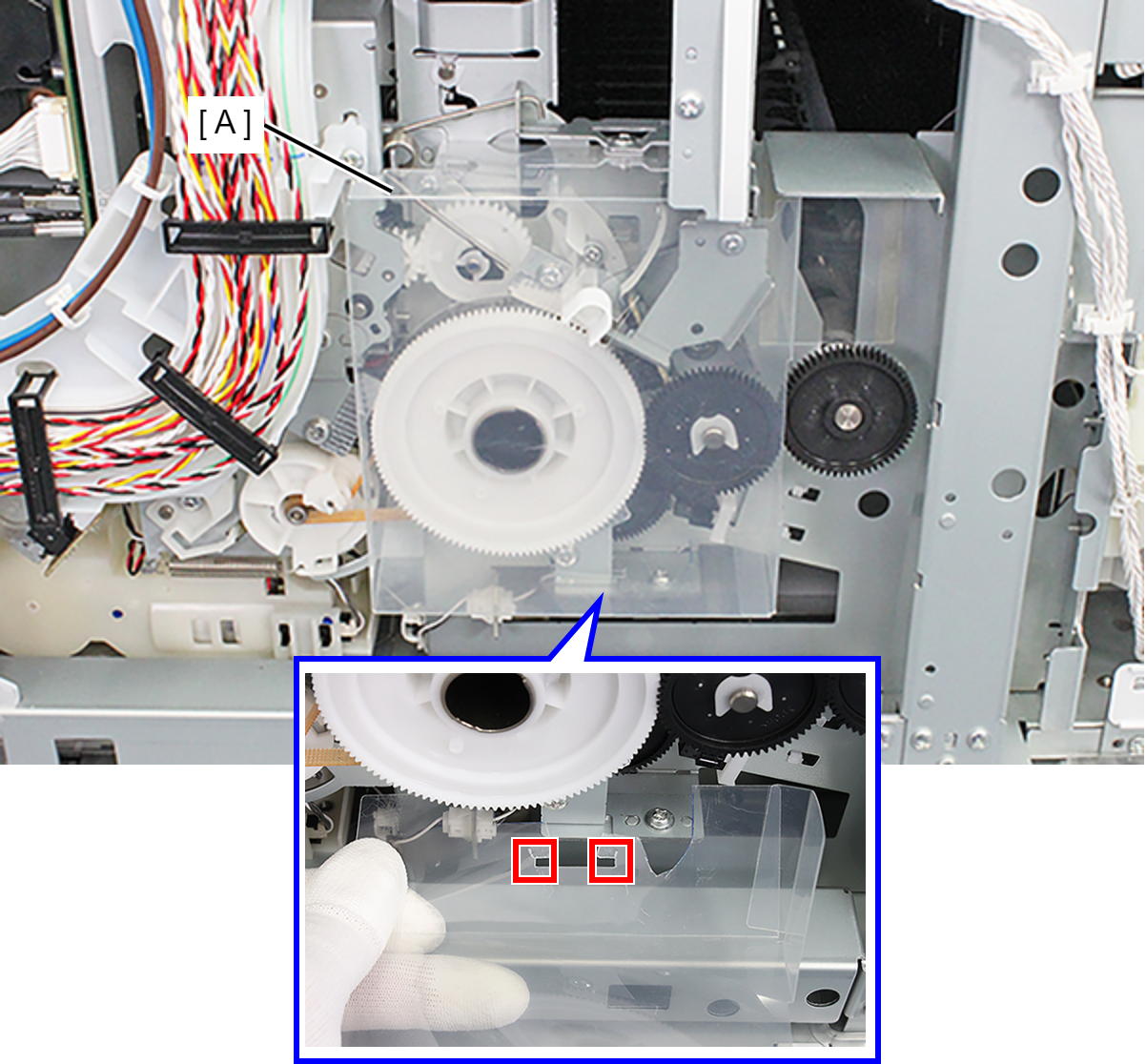
- Release the cable from the two clamps (A).
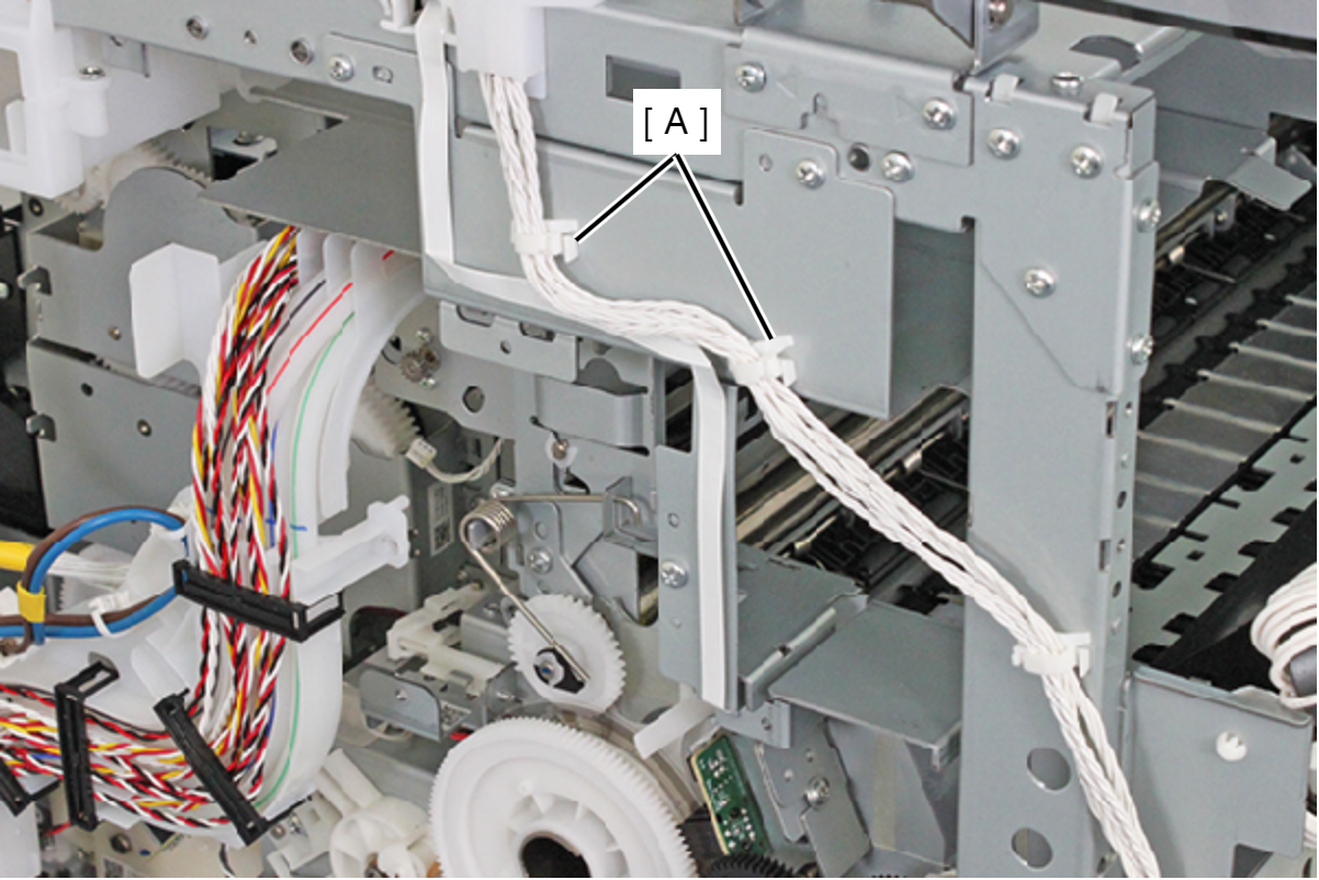
- Remove the FFC from the connector of the PF Encoder Assy (A) and release the FFC by peeling away the double-sided tape.
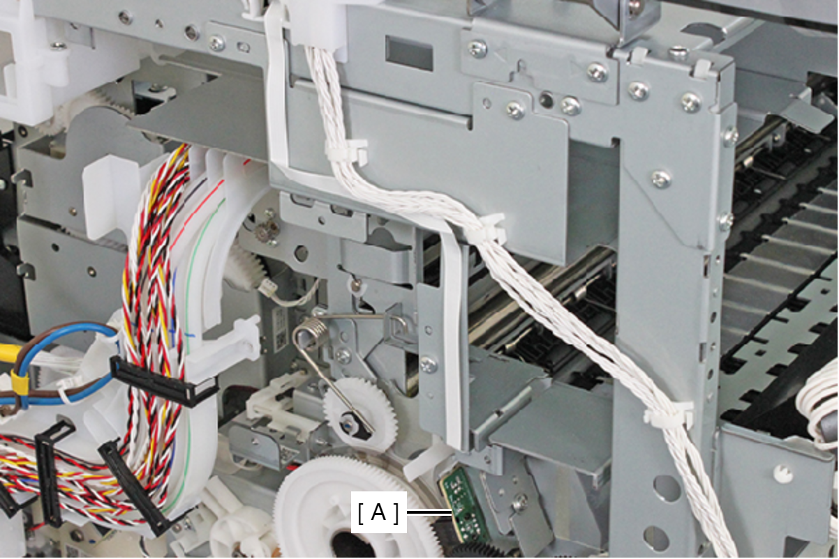 Caution / 注意
When removing the PS Guide Left (A), be careful not to damage the cable or FFC on the sharp edge of the PS Guide Left(A).
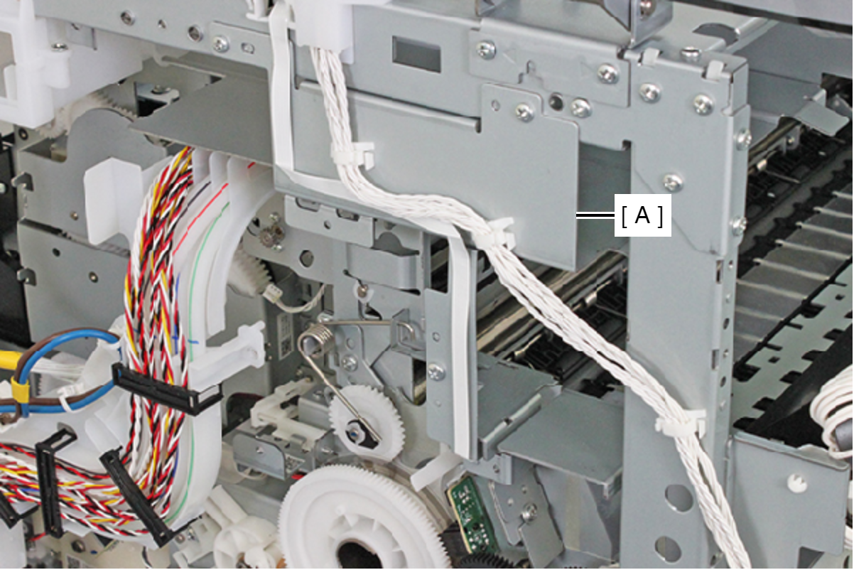
- Remove the three screws and remove the PS Guide Left (A) toward the direction of the arrow.
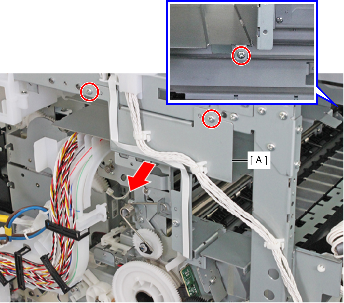
- : C.B.S-TITE-SCREW-3x8-F.ZN-3C
- Remove the five screws, and remove the PS Guide Right (A).
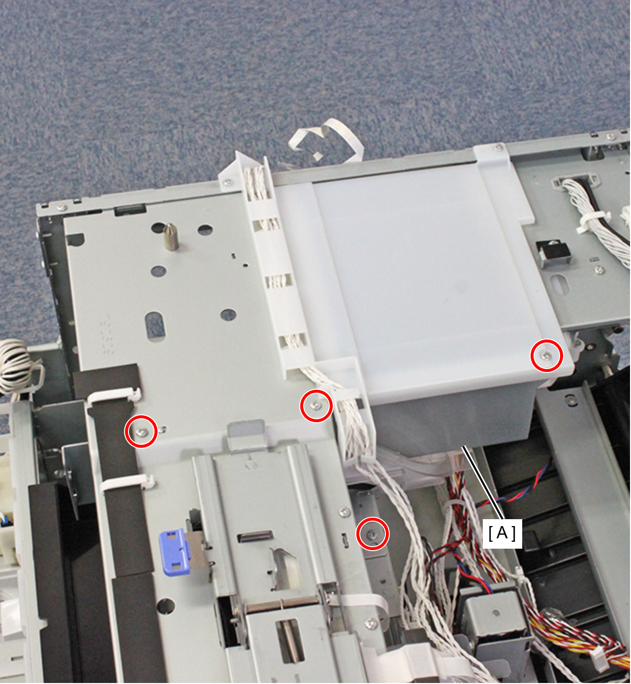
- : C.B.S-TITE-SCREW-3x8-F.ZN-3C
- Remove the screw on the rear side of the product, then remove the Paper Jam Clear Cover Holder (A).
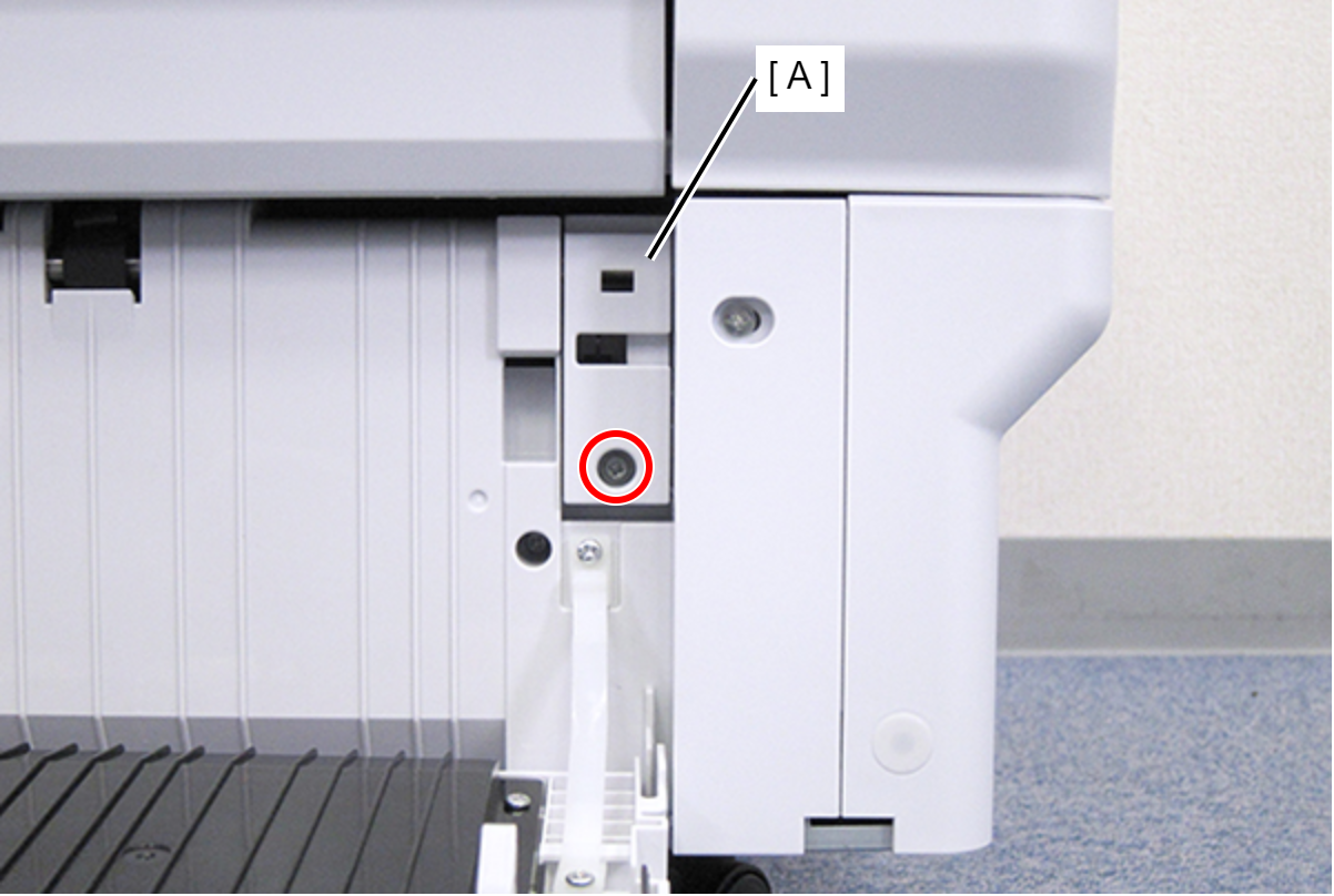
- : C.B.S-TITE-SCREW-3x8-F.ZN-3C
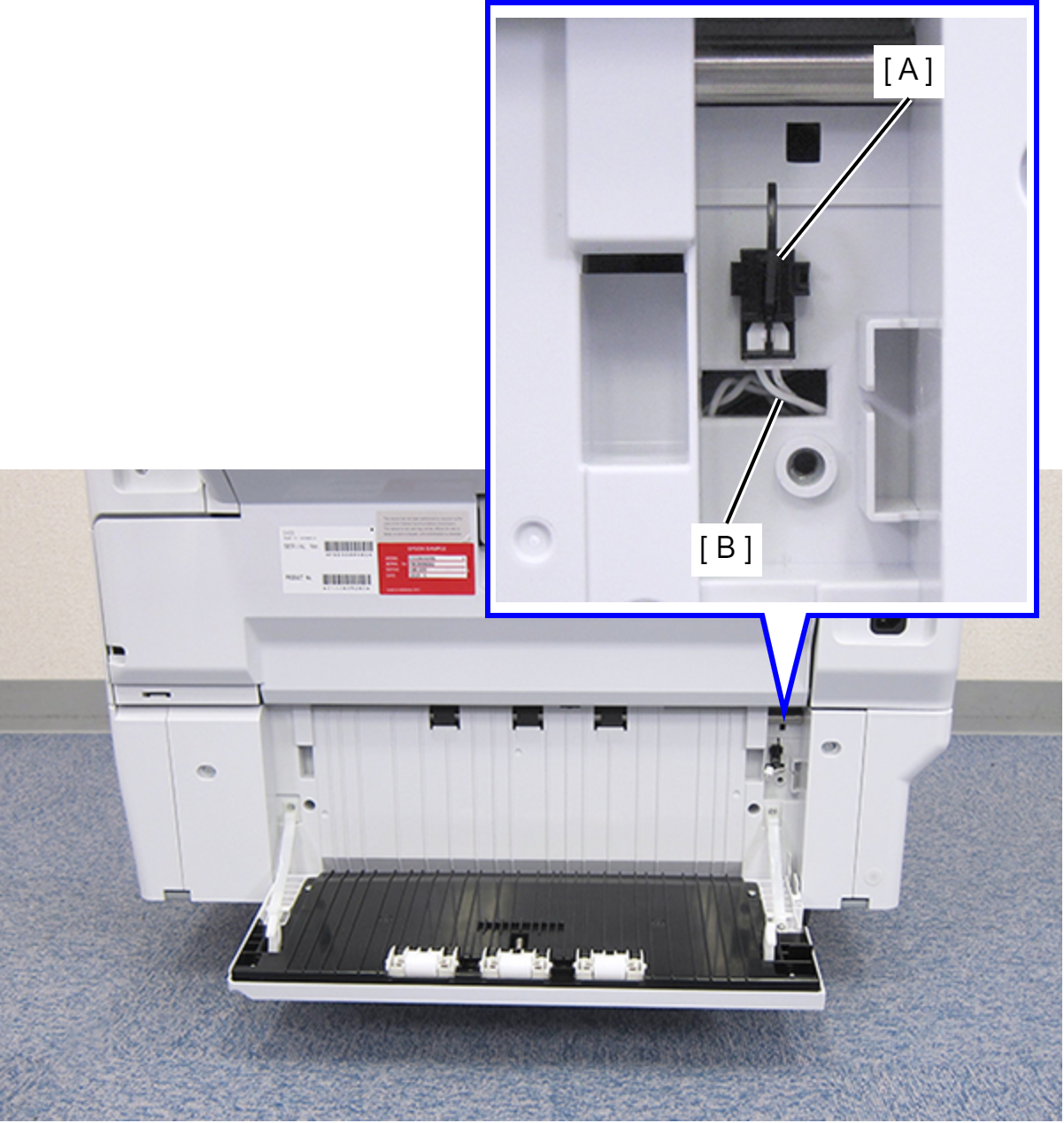
- Disconnect the cable (B) from the connector of the Rear RIPS Cover Sensor (A).
- Remove the four screws that secure the Rear RIPS Housing Assy (A).
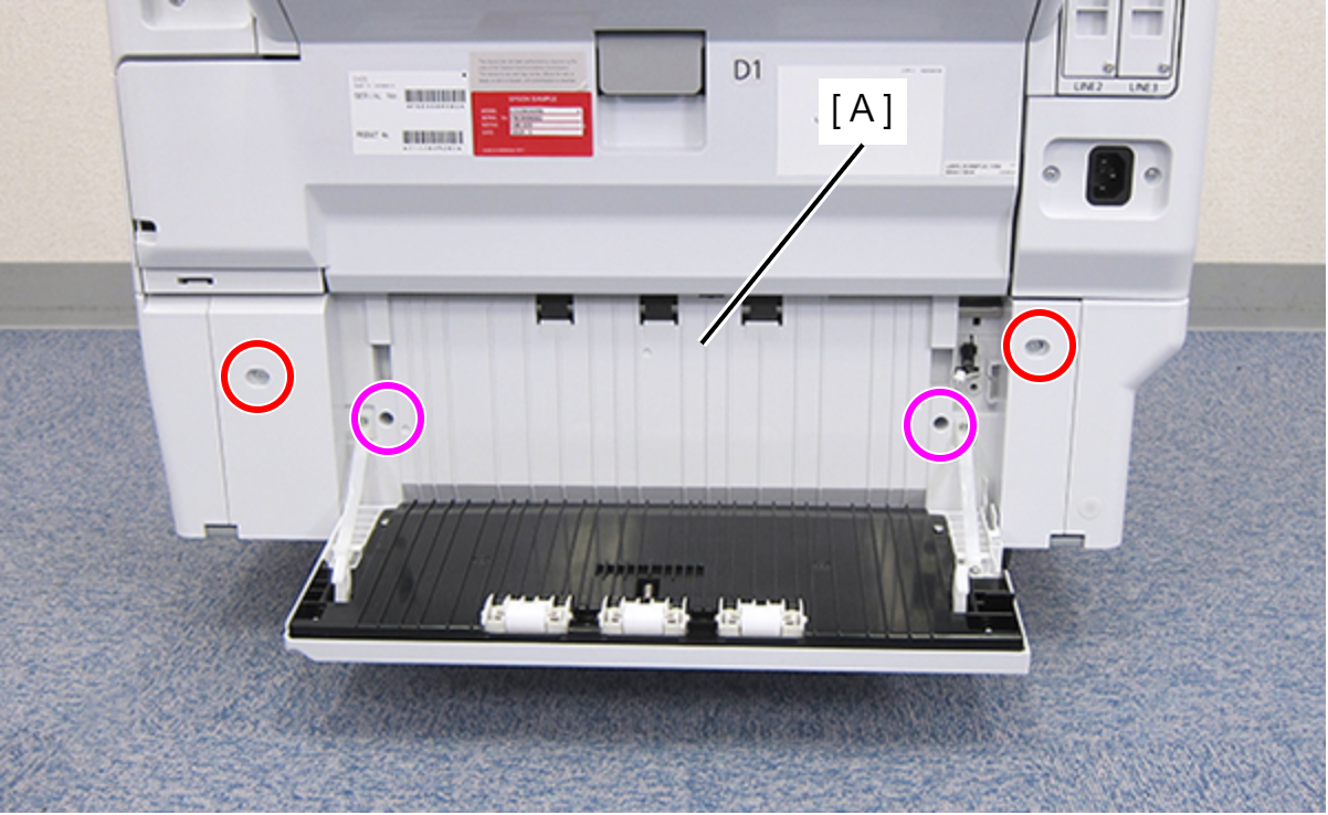
 : C.SHOULDER S-TITE,3X5
 : C.B.P-TITE-SCREW-3x10-F.ZN-3C
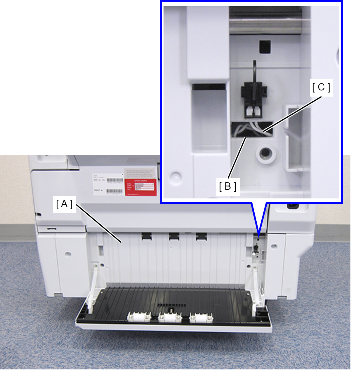
- Remove the Rear RIPS Housing Assy (A) pulling out the cable (C) through the hole (B) of the assy.
 Assembly / 組み立て
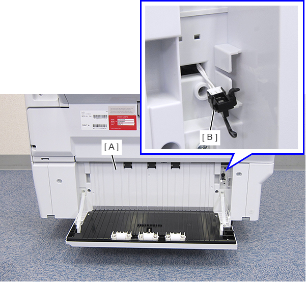
Before reinstalling the Rear RIPS Housing Assy (A), remove the Paper Jam Clear Cover Sensor (B). After connecting the cable, install the sensor to the Rear RIPS Housing Assy.
- Remove the two screws on each side.
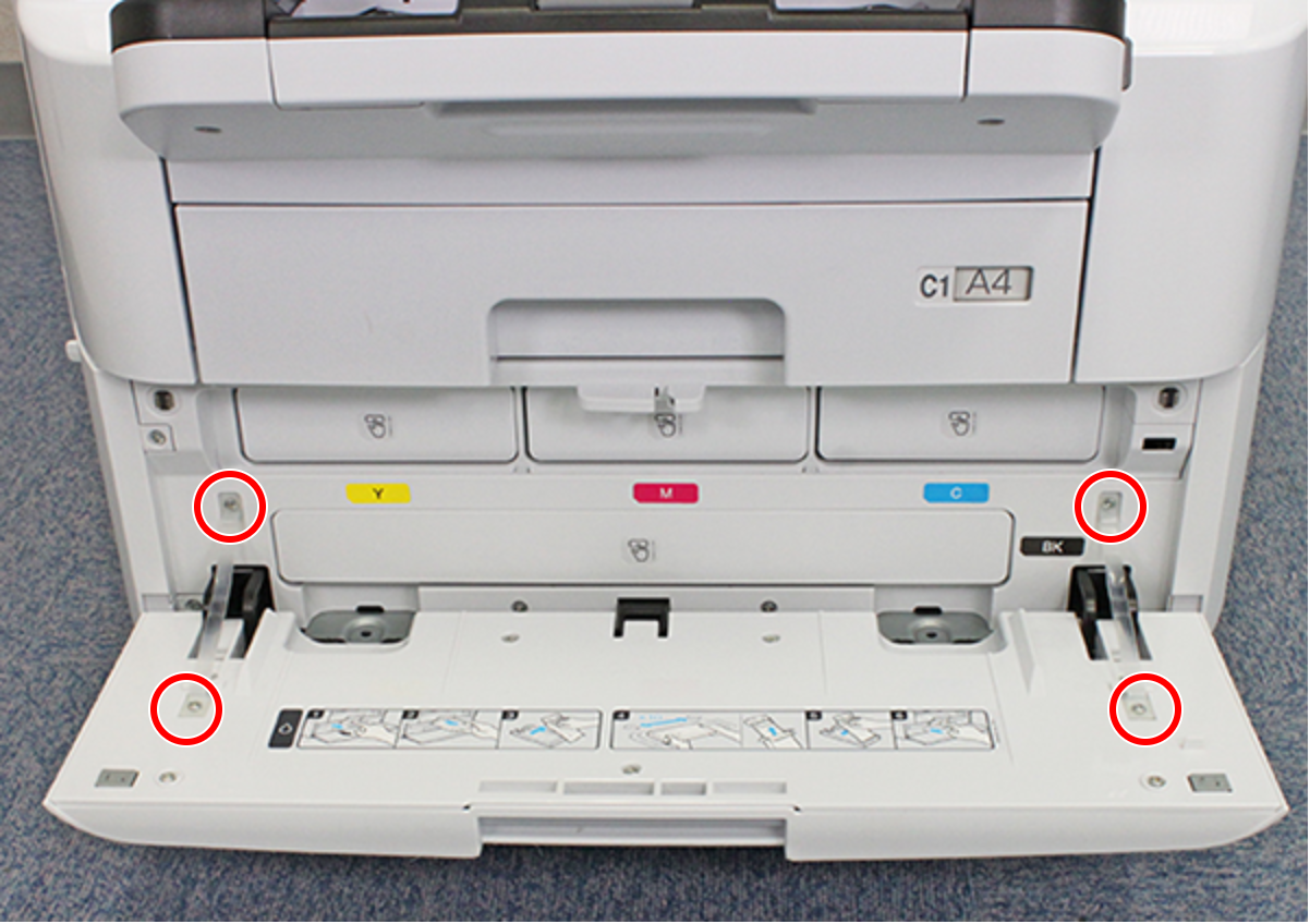
- : C.B.P-TITE-SCREW-3x10-F.ZN-3C
- Release the two hooks on each side and remove the two Ink Pack Cover Belts (A).
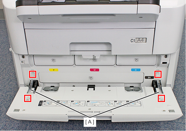
- Release each hook and remove the two Hinge Covers (A).
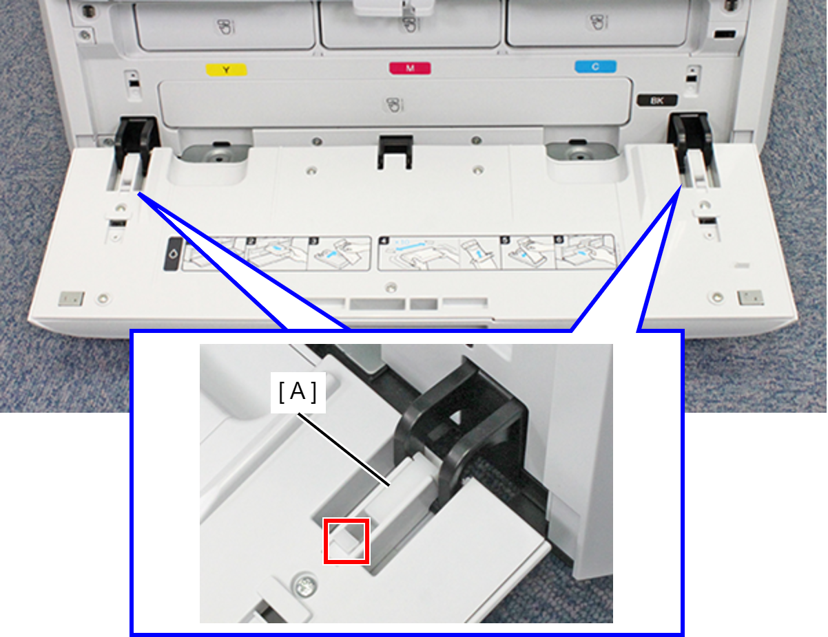
- Remove the Ink Pack Cover (B from the three hinges (A).
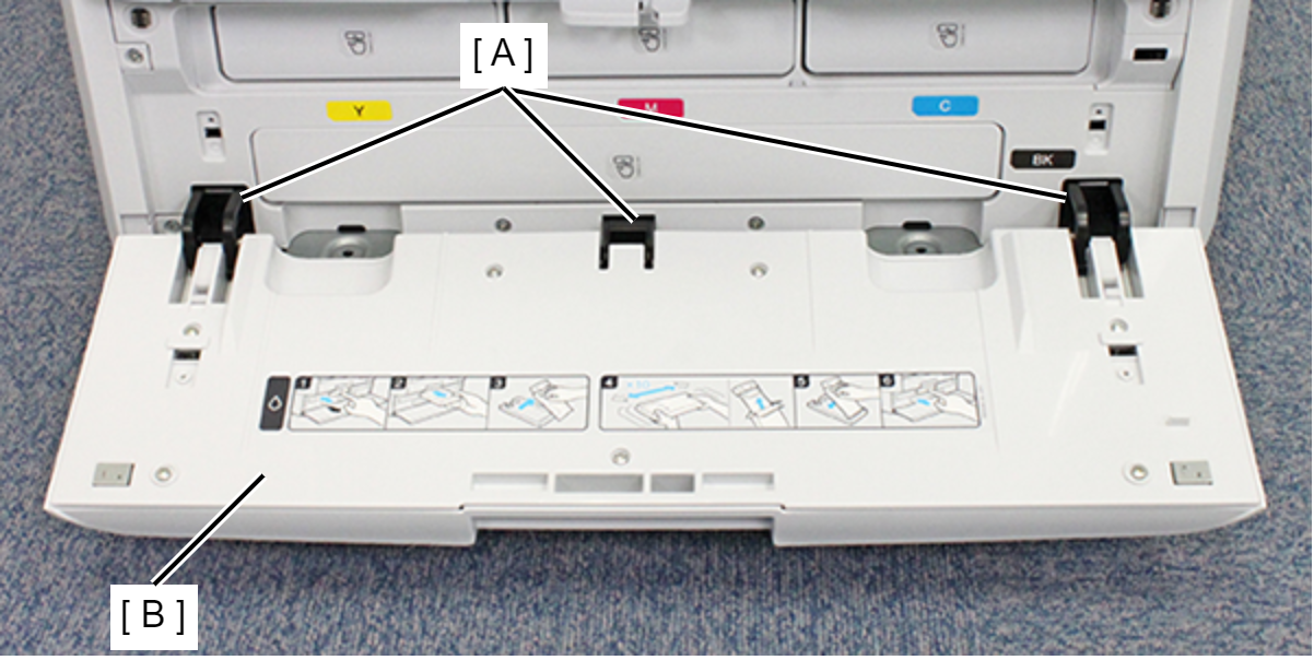
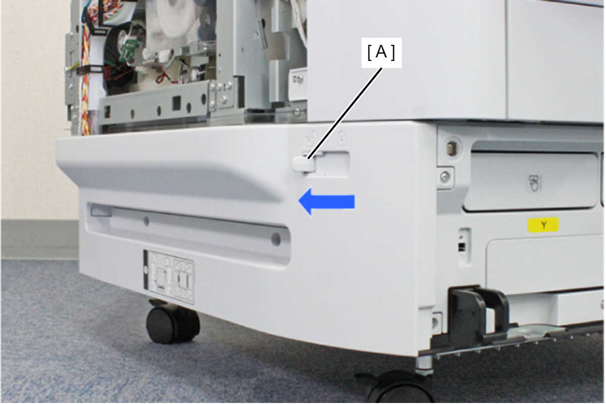
- Move the Lock Lever (A) in the direction of the arrow to set the Ink Pack Cover lock in the released state.
- Remove the two screws fastening the Left RIPS Housing Assy (A).
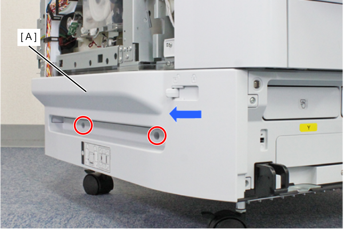
- : C.SHOULDER S-TITE,3X5
- Remove the two screws fastening the Left RIPS Housing Assy (A).
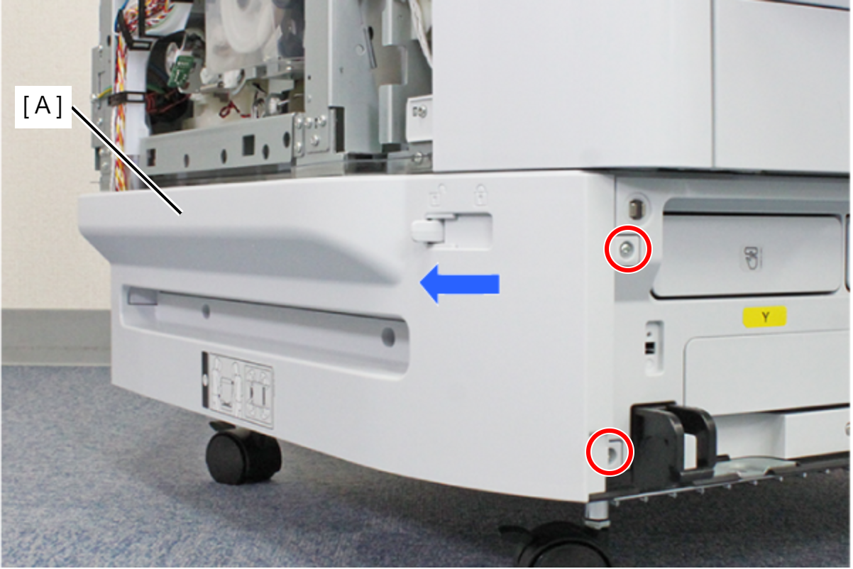
- : C.B.P-TITE-SCREW-3x10-F.ZN-3C
- Lift the Left RIPS Housing Assy (B) and rotate in the direction of the arrow while releasing the two hooks to release the interfering unit (A) behind the Left RIPS Housing Assy (B).
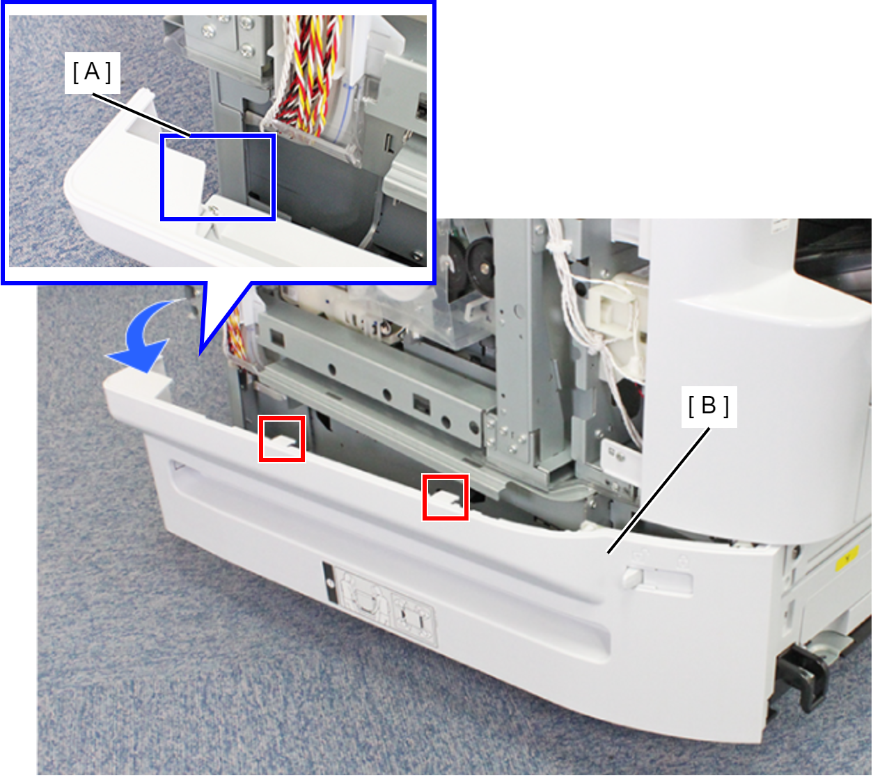
- Remove the three ribs and remove the Left RIPS Housing Assy (A).
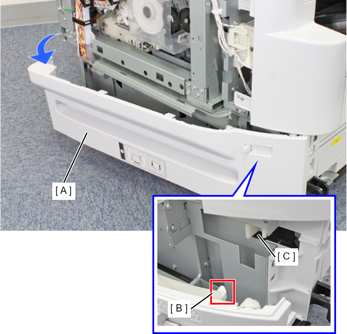
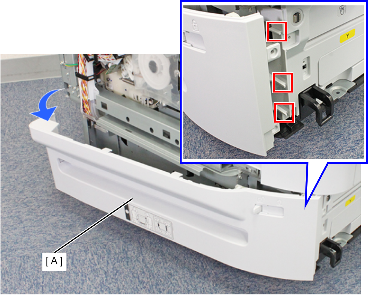 Assembly / 組み立て
When mounting the Left RIPS Housing Assy (A), mount by aligning the Lock Lever Shaft (B) and the receiving part (C).
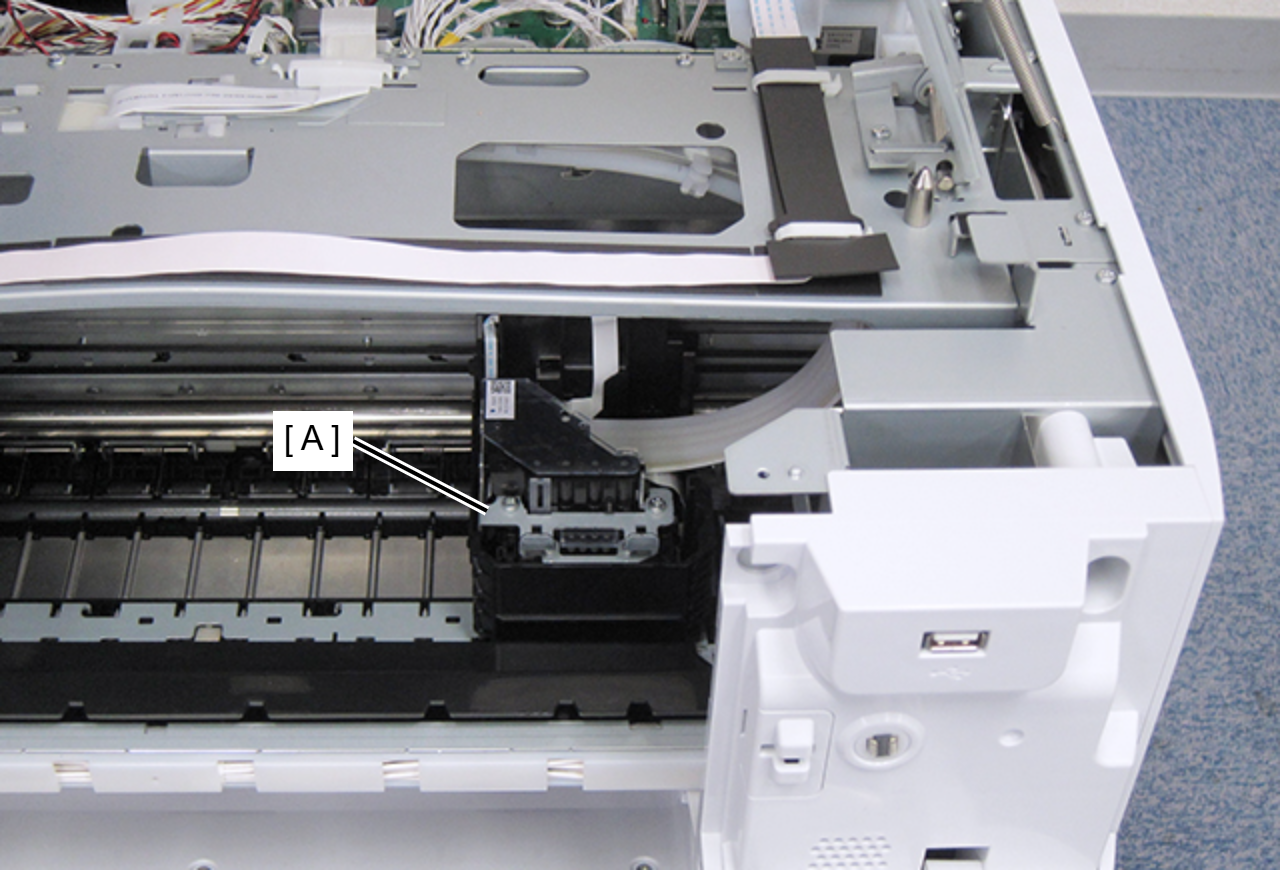
- Move the CR Unit (A) to the print head replacement position.
- Remove the three screws that secure the ink tube joint portion.
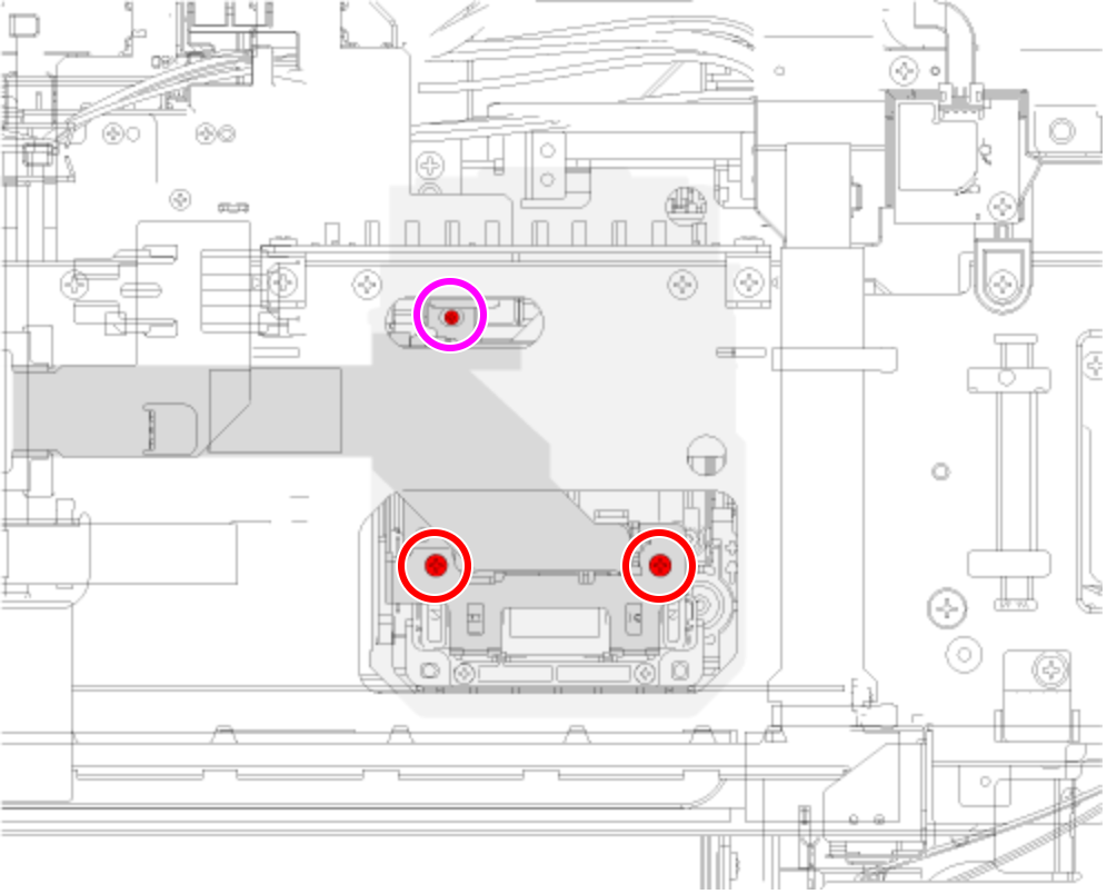
- : C.B.S2-SCREW-3x12-F.ZN-3C
 : C.B.P-TITE-SCREW-2.5x10-F.ZN-3C
Remove the ink tube joint portion.
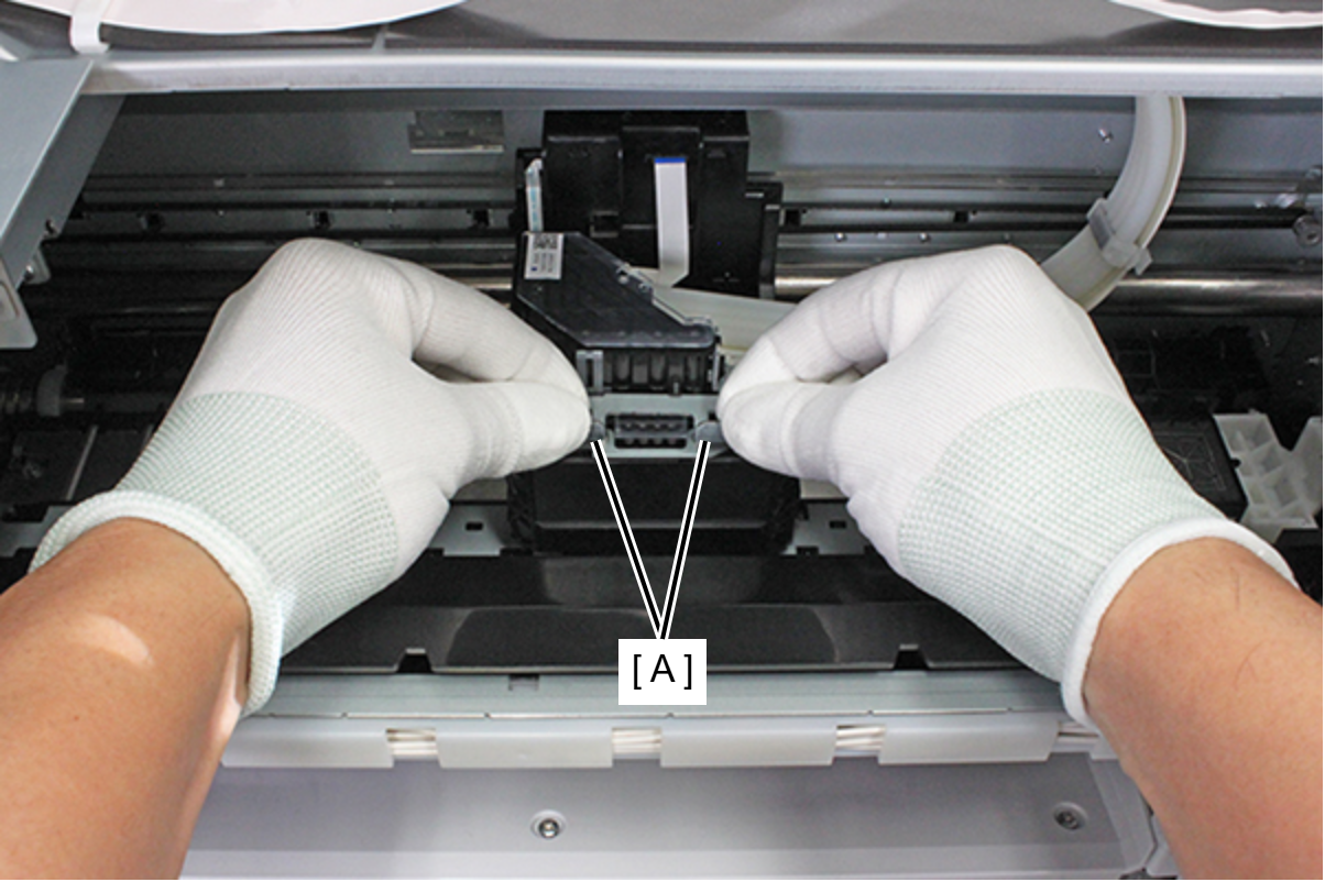
Caution / 注意To prevent the ink tube joint portion from being damaged, hold the frame (A) of the ink tube joint portion with both hands and remove the joint portion straight upward.
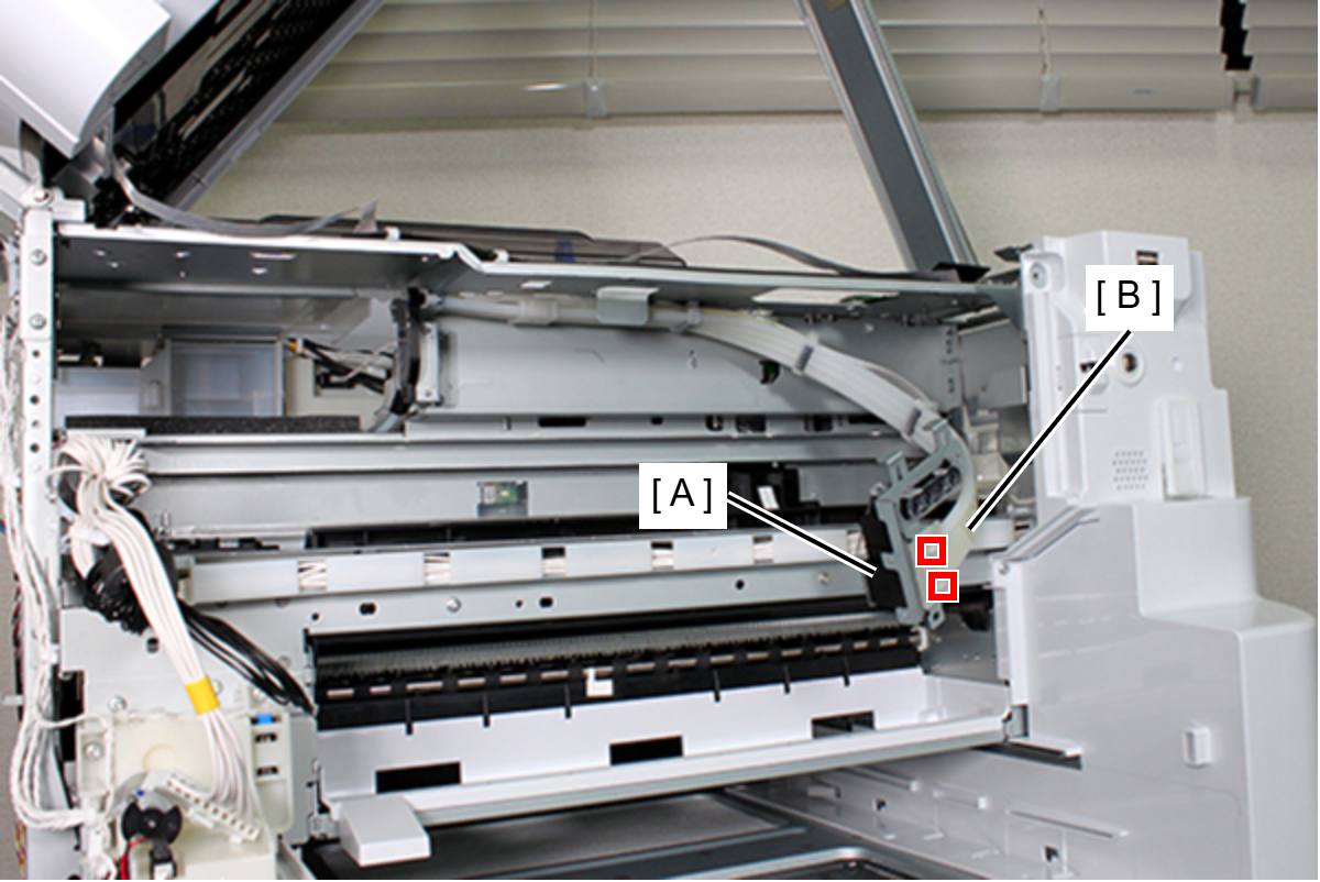
- Release the two hooks and remove the FFC Guide Plate (B) from the Ink Tube Joint (A).
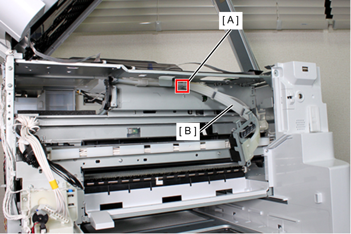
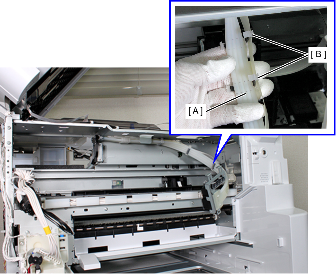
- Release each hook on Clamp A (A) and remove the Ink Tube (B) from Clamp A.
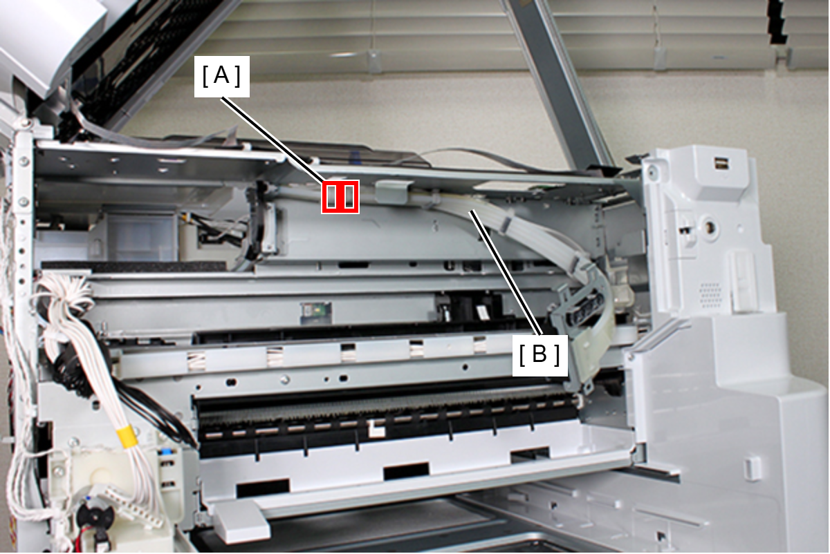
- Release the two hooks on each Clamp B (A) and remove the Ink Tube (B) from Clamp B.
- Remove the two screws and remove the Ink Tube Relay Holder (A).
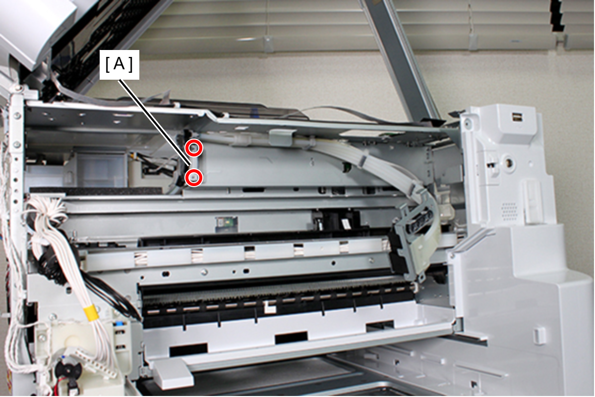
- : C.B.S-TITE-SCREW-3x8-F.ZN-3CAssembly / 組み立て
When fastening the Ink Tube (A) to Clamp A (B), align Clamp A to the dotted line position on the Ink Tube.
- Remove the screw fastening the Tube Guide (A).
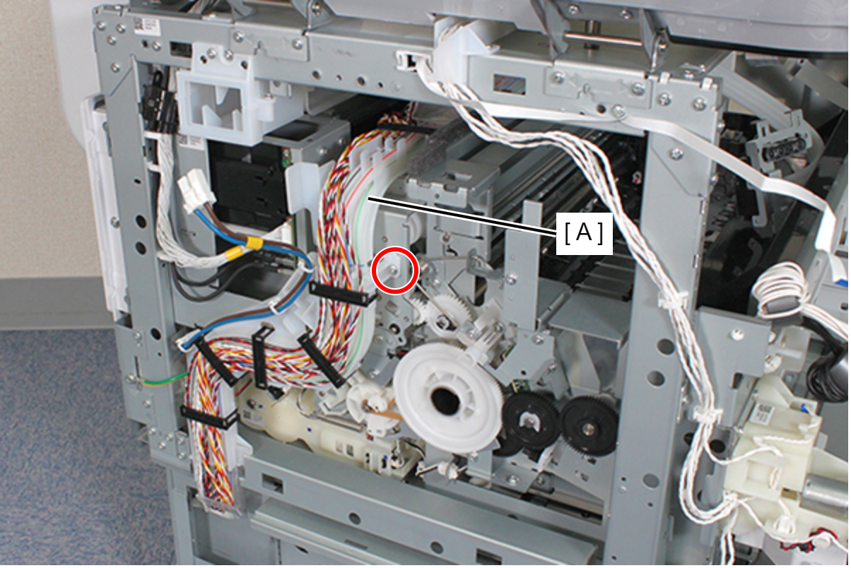
- : C.B.S-TITE-SCREW-3x8-F.ZN-3C
- Release the Power Supply Unit Cable (B) from the three clamps (A).
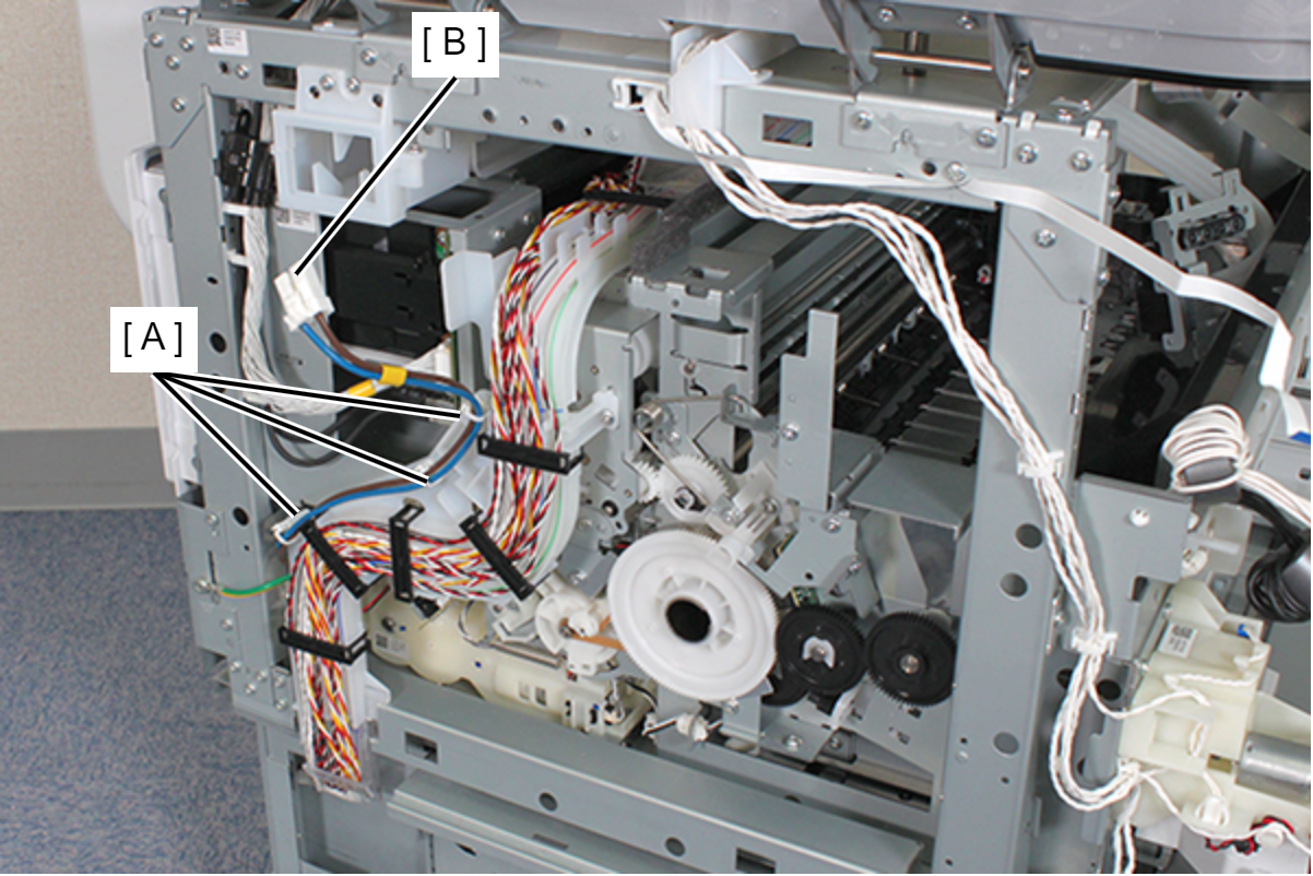
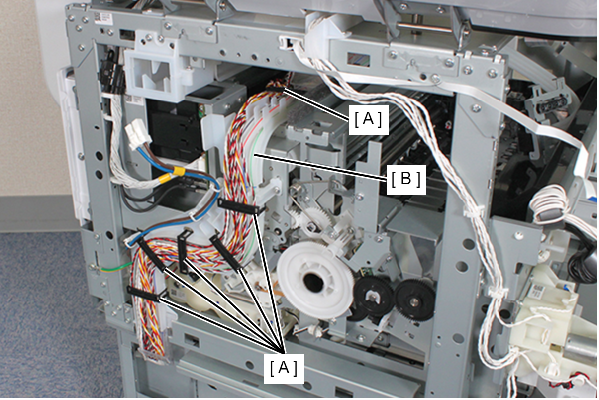
- Remove the six Cable Clips (A) and release the cable from the Tube Guide (B).
- Remove the screw that secures the Ink Tube Holder (A).
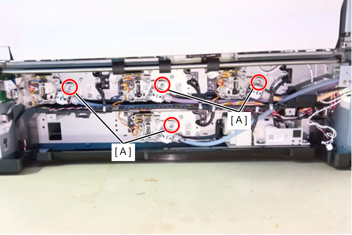
- : C.B.P-TITE-SCREW-3x10-F.ZN-3C
Caution / 注意When removing or attaching the Ink Tube Holder (A), move it straight up or down to prevent its inlet from being tilted.
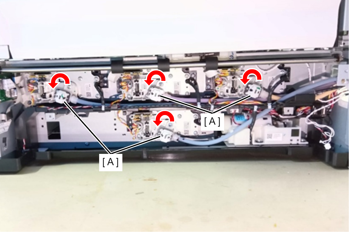
- Rotate the Ink Tube Holder (A) counterclockwise, and then remove the its.
- Release the Ink Tube (A) from other cables and parts.
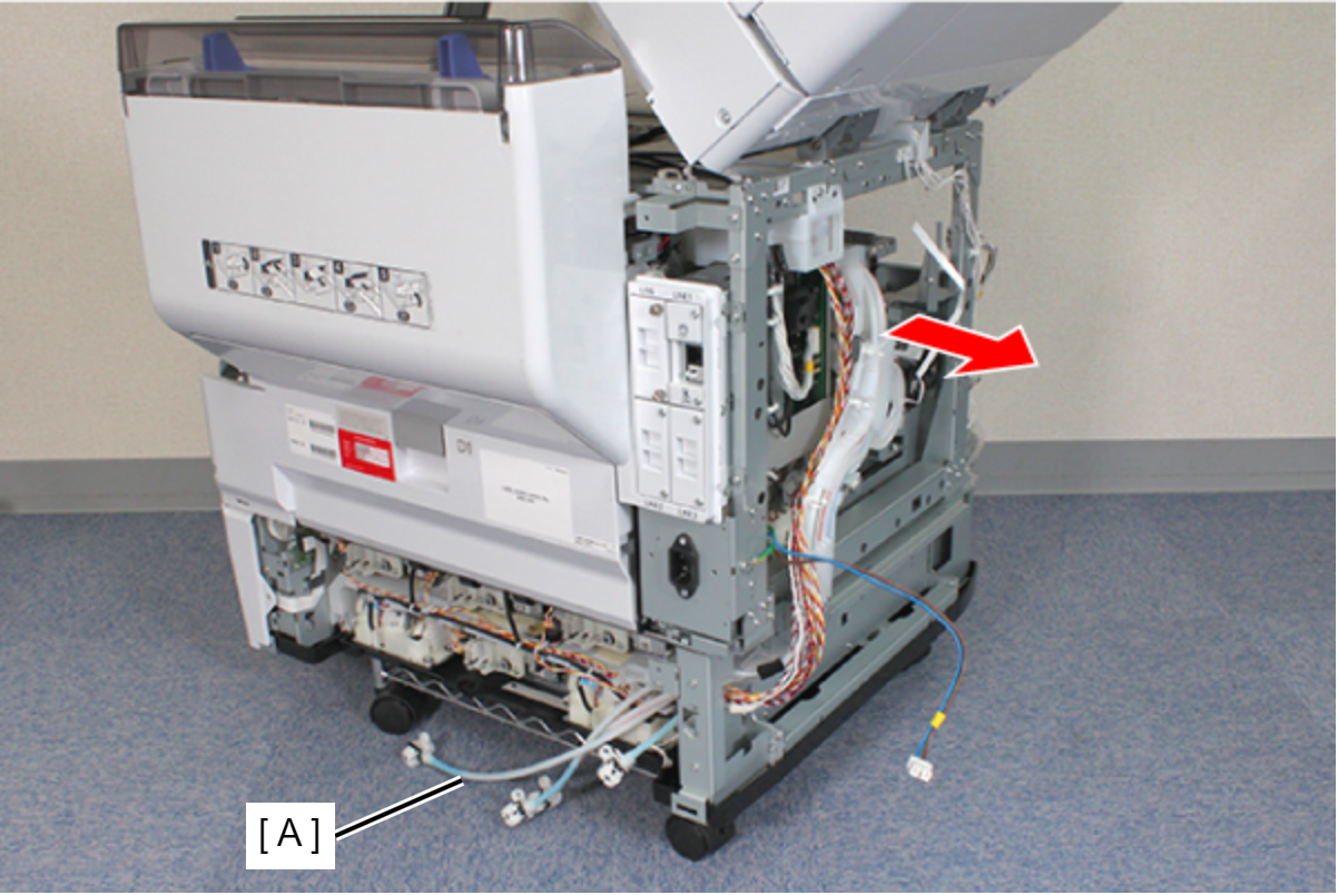
- Remove the Ink Supply Tube Assy (C) while pulling out the Ink Tube (A) through the hole (B) in the frame.
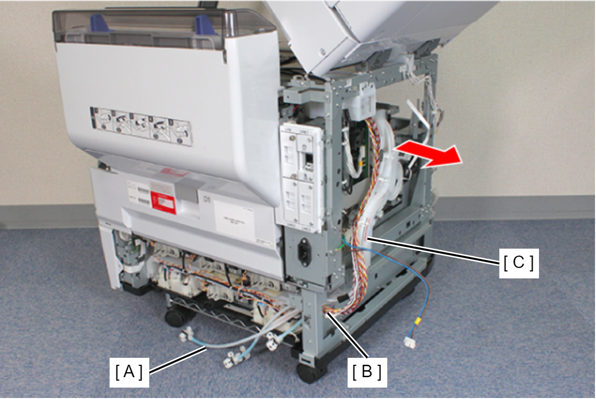 Assembly / 組み立て
When routing the ink tube (A) near the ink supply unit (Y), route the ink tube (A) in the order of (B), (C), (D) and (E).
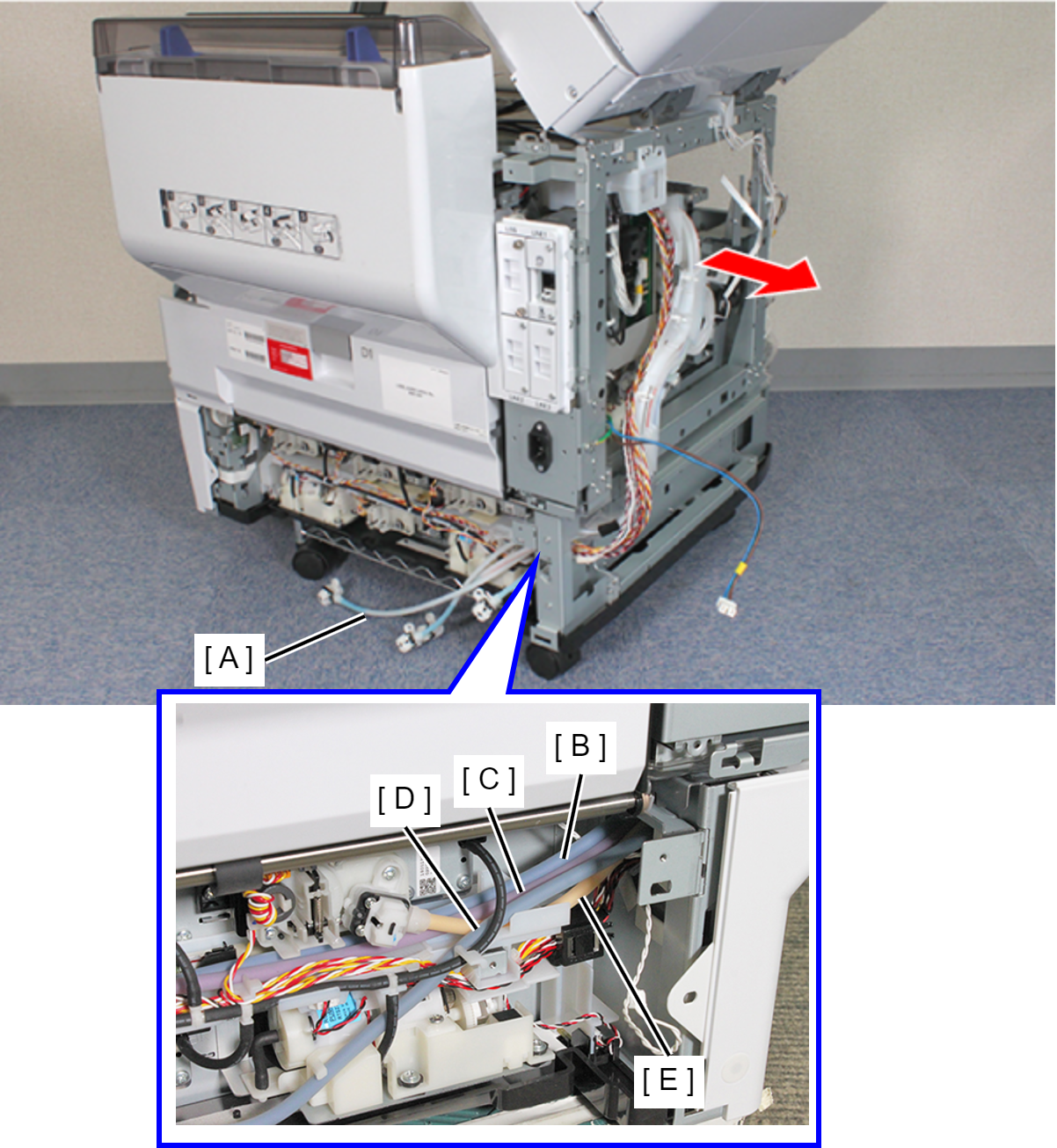
- B: Cyan
- C: Magenta
- D: Black
- E: Yellow