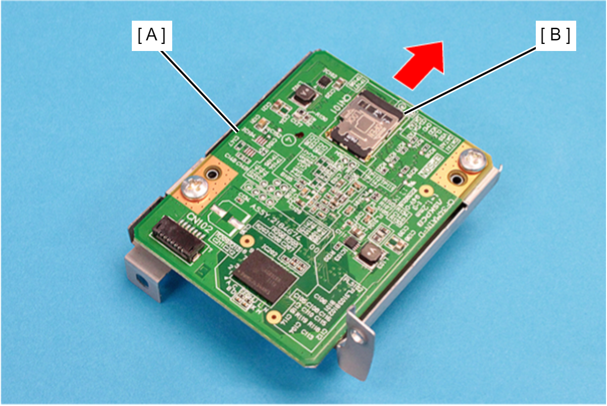
SD Memory (EP-C800 Series)
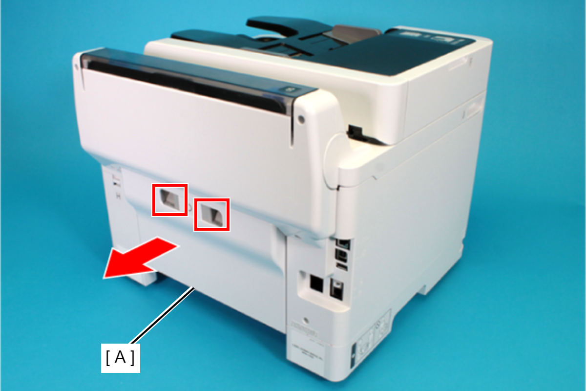
- Remove the Rear Unit (A) in the direction of the arrow while pressing the buttons inward.
- Open the ASF Cover (A) and remove the two screws securing the Rear Housing Assy (B).
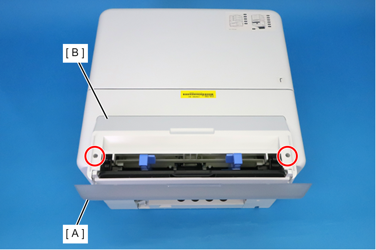
 : C.B.P-TITE-SCREW-3x10-F.ZB-3C
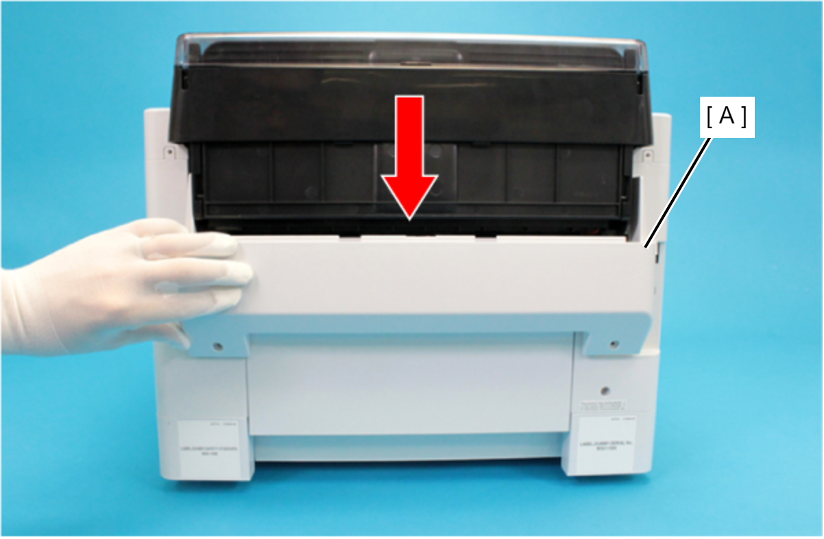
- Remove the four screws that secure the Rear Back Cover (A).
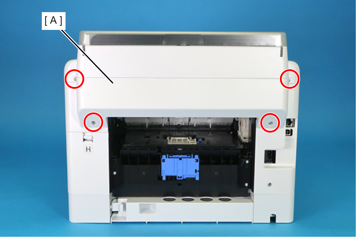
 : C.B.P-TITE-SCREW-3x10-F.ZN-3C
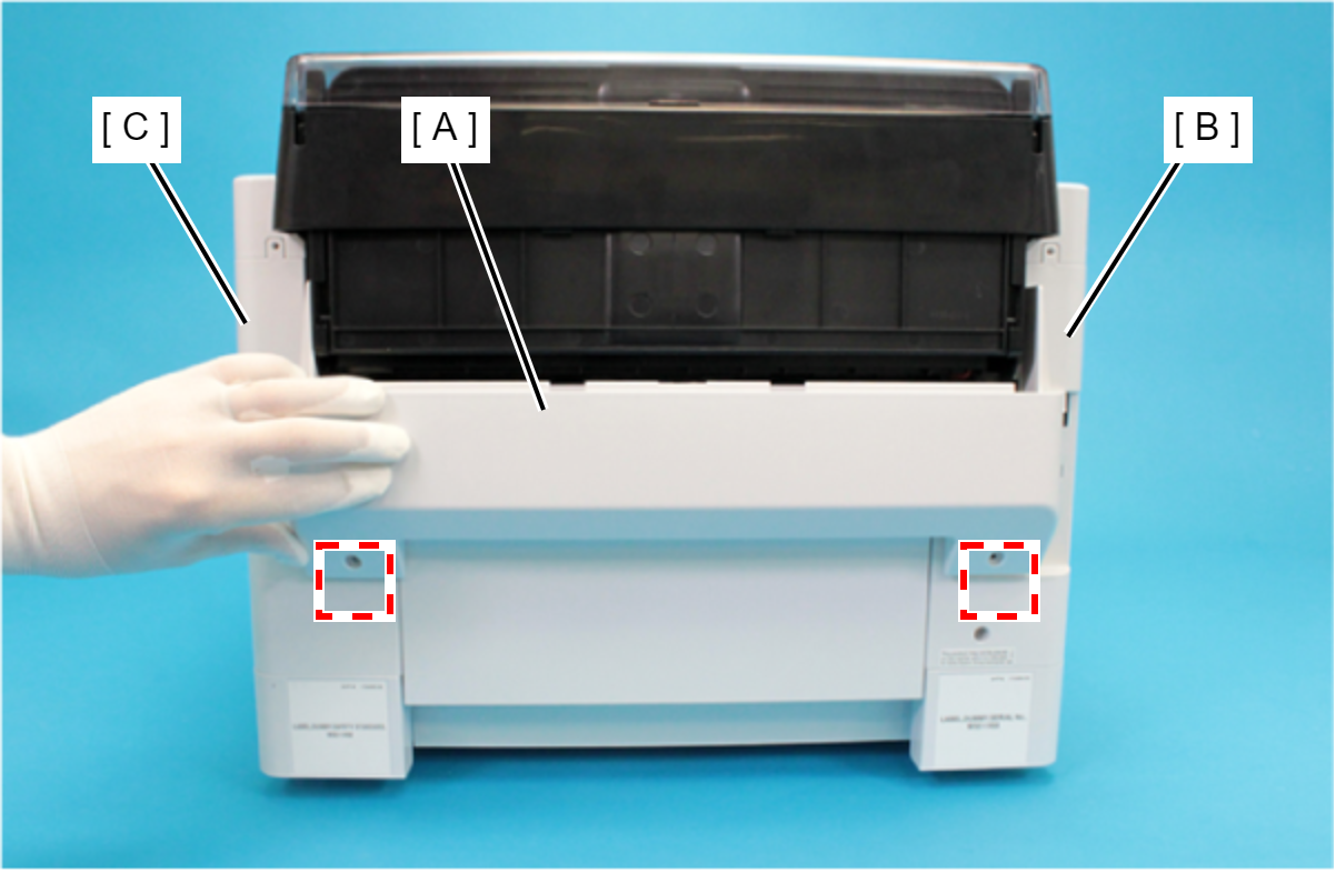
- Remove the Rear Back Cover (A) downward.
 Assembly / 組み立て
Attach the two dowels of the Rear Back Cover (A) to the positioning holes on the Housing Left (B) and the Housing Right (C).
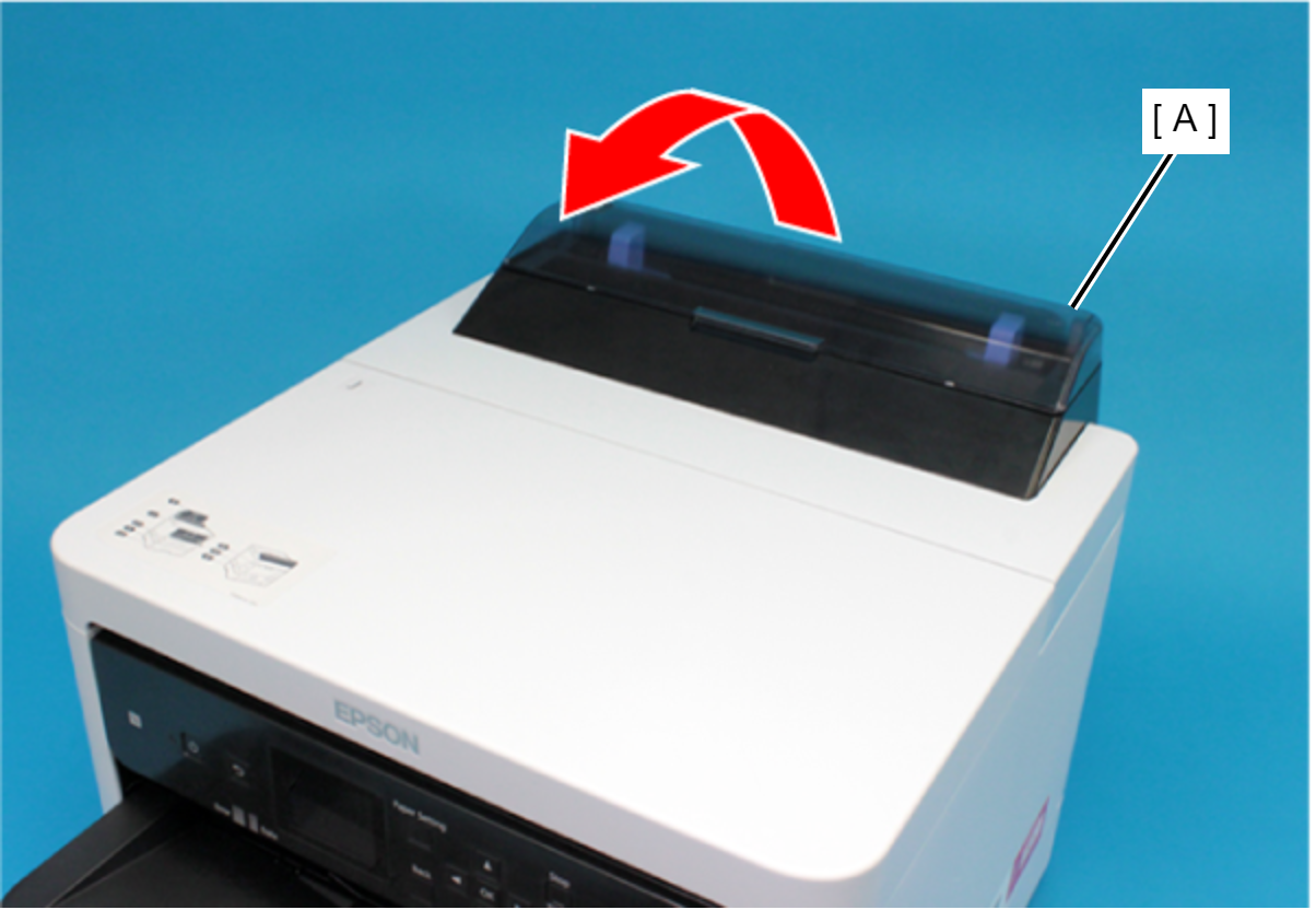
- Remove the Rear Upper Cover Assy (A) in the direction of the arrow.
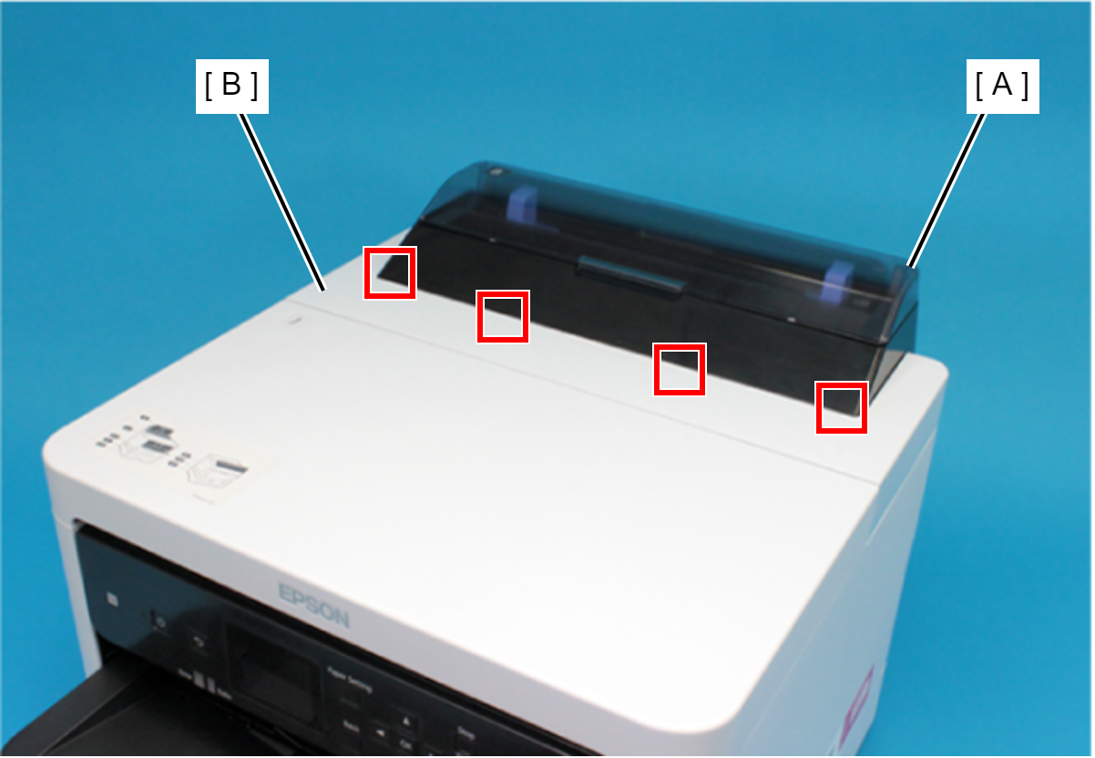
 Assembly / 組み立て
Insert the four tabs of the Rear Upper Cover Assy (A) to the positioning holes of the Housing ASF (B).
- Remove the two screws securing the Housing ASF (A).
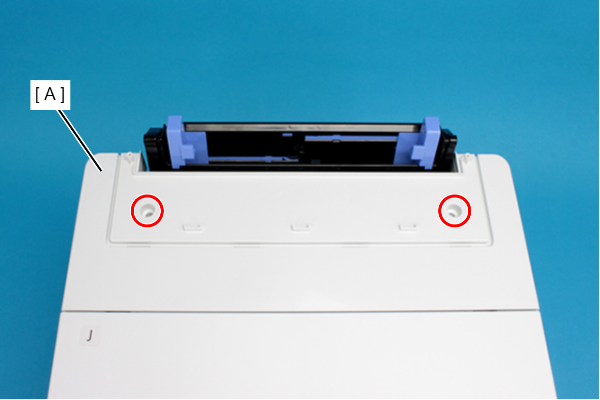
- : C.B.P-TITE-SCREW-3x10-F.ZN-3C
- Open the Printer Cover (A) and remove the four screws, and then remove the Housing ASF (B).
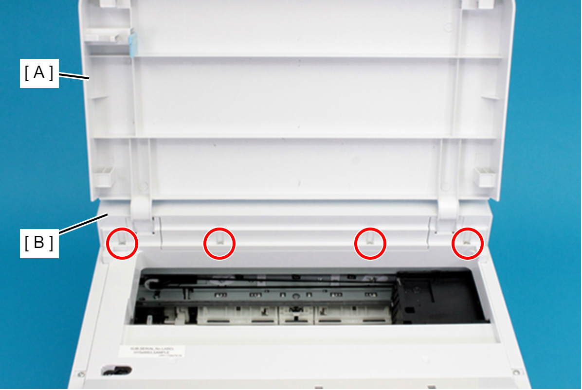
- : C.B.P-TITE-SCREW-3x10-F.ZN-3C
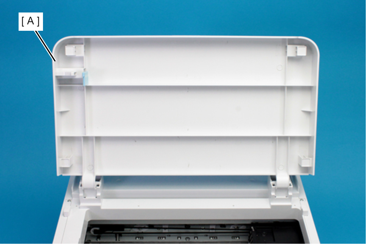
- Remove the Printer Cover (A) upward.
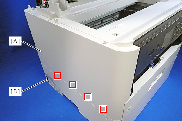
- Remove the three screws that secure the Housing Left (A).
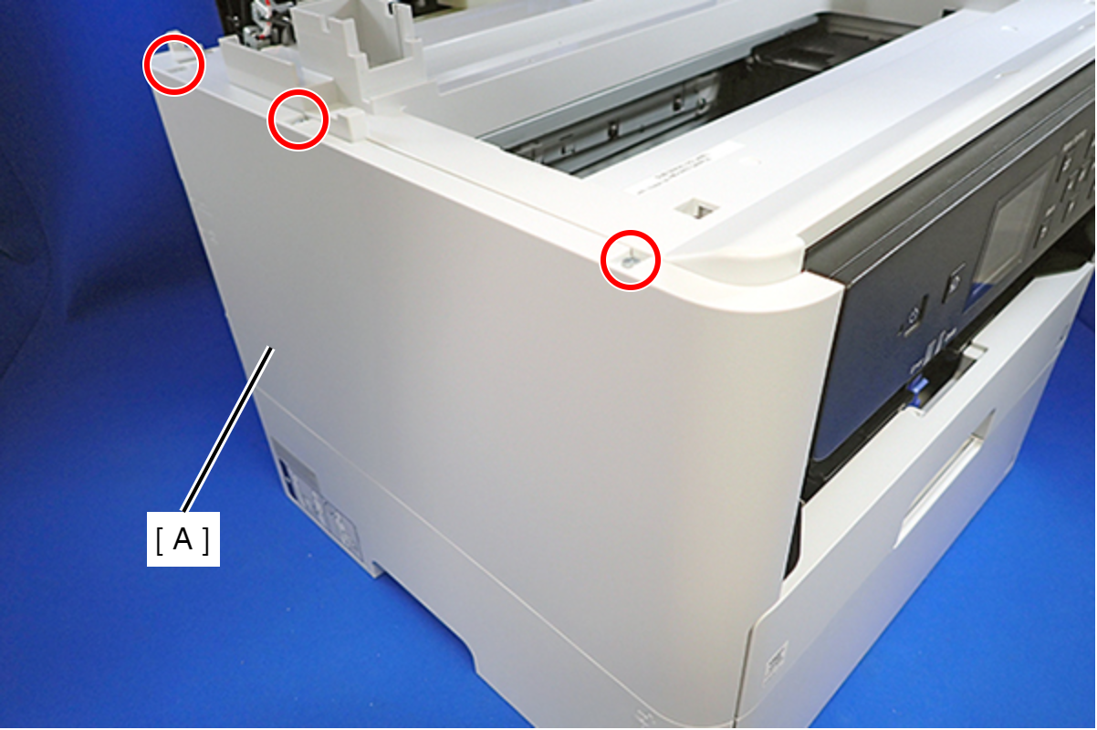
- : C.B.P-TITE-SCREW-3x10-F.ZN-3C
- Remove the two screws that secure the Housing Left (A).
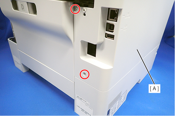
- : C.B.P-TITE-SCREW-3x10-F.ZN-3C
- Lift the Housing Left (A) to release the two hooks each on the front side and rear side of the Housing Left (A), and then remove the Housing Left (A).
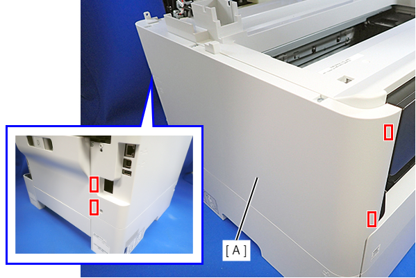
Assembly / 組み立てInsert the four tabs on the Housing Left (A) to the positioning holes of the Ink Supply Unit (B).
- Peel off the CRCM FFC (B) from the CRCM FFC Sheet (A).
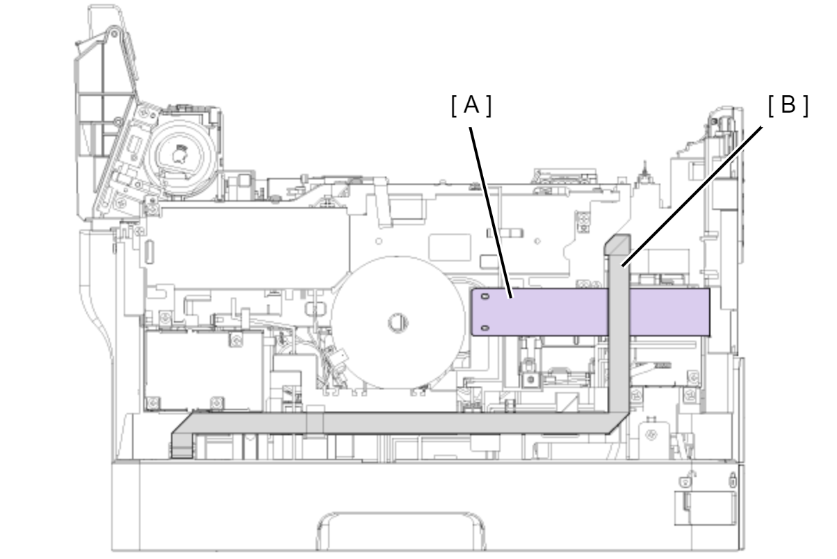
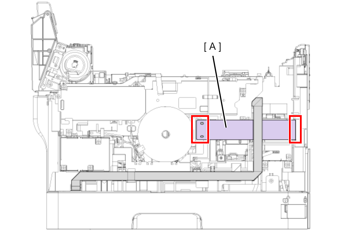
- Peel off the double-sided tape at two locations and then remove the CRCM FFC Sheet (A).
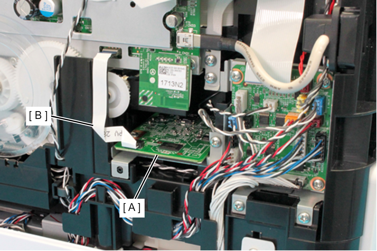
- Disconnect the FFC (B) from the connector (CN102) of the PDL Board (A).
- Remove the screw and remove the PDL Board Assy (A).
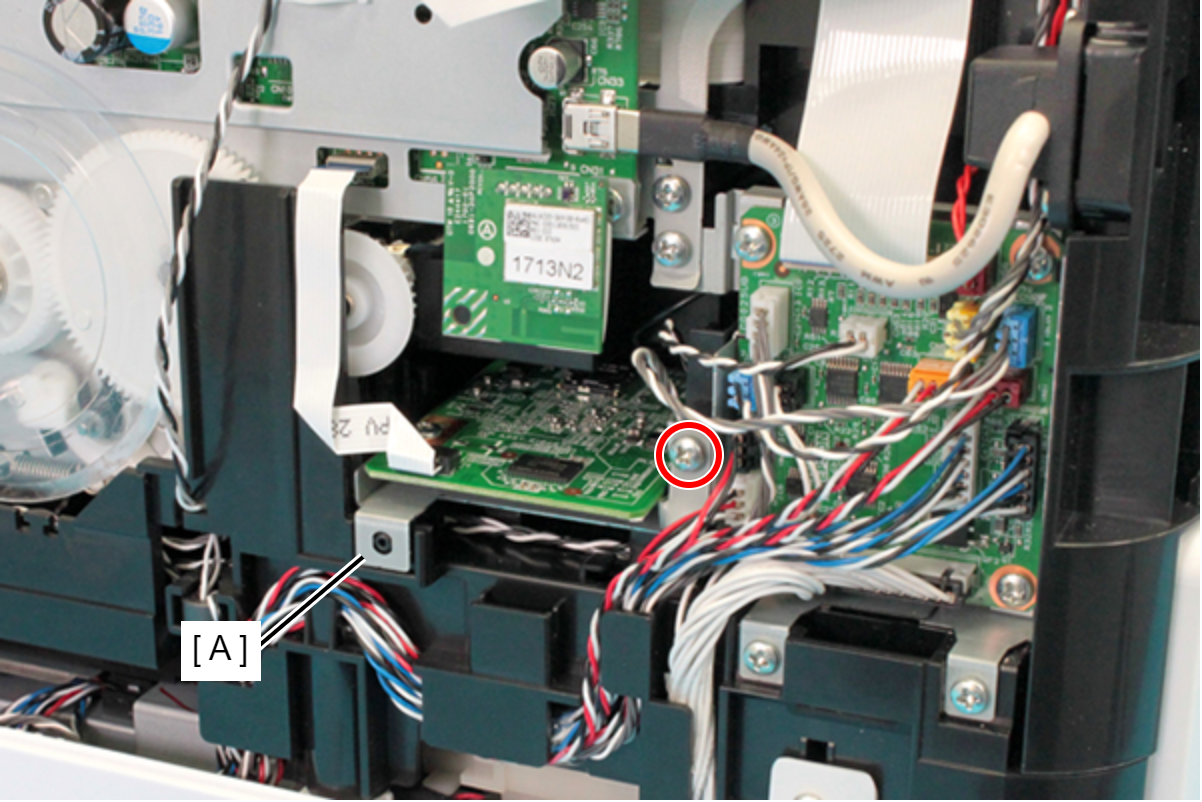
- : C.B.S-TITE-SCREW-3x6-F.ZN-3C
- Remove the SD Memory (B) from the PDL Board Assy (A) in the direction of the arrow.