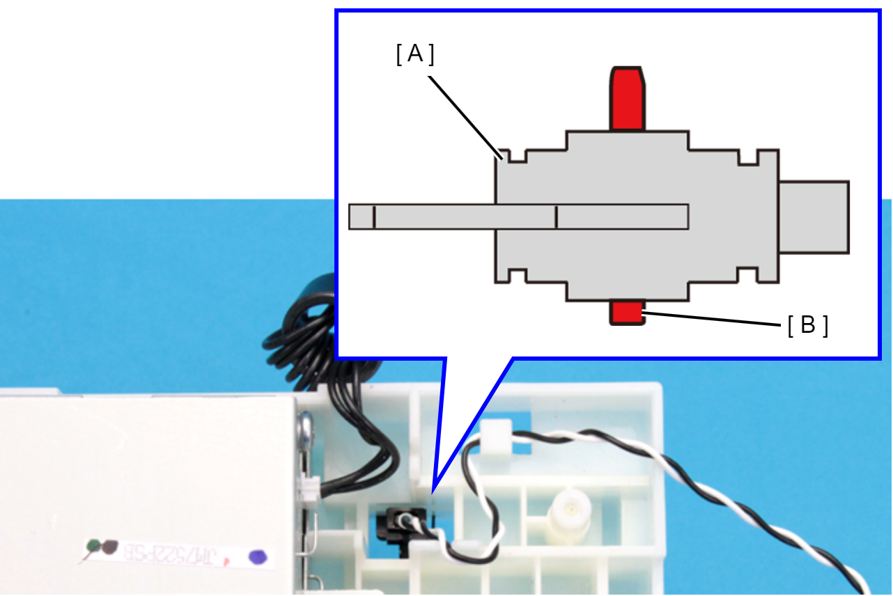
Rear Unit Detection Sensor (EM-C800 Series)
- Remove the four screws, then remove the Rear Cover (Back) (A).
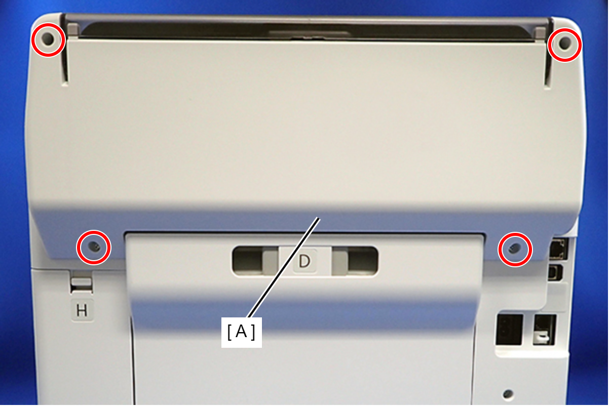
 : C.B.P-TITE-SCREW-3x10-F.ZN-3C
 Assembly / 組み立て
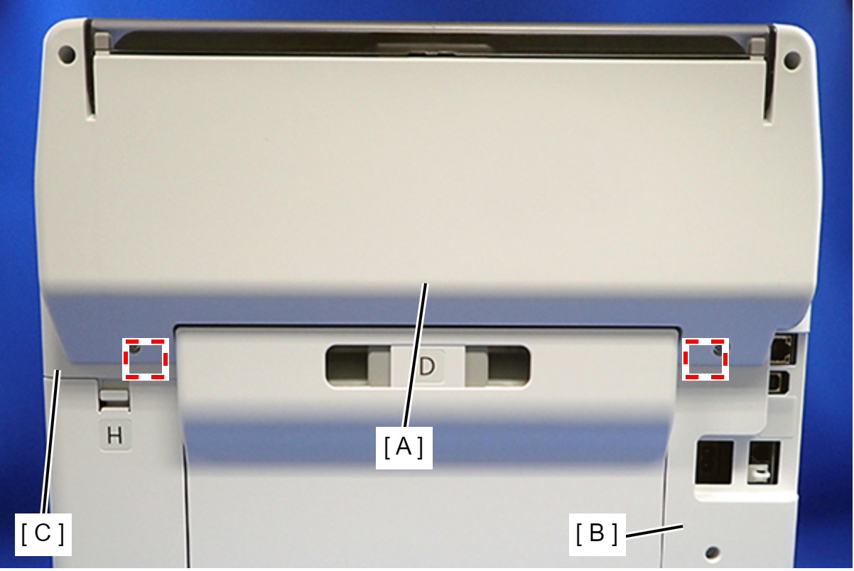
Attach the two dowels of the Rear Cover (Back) (A) to the positioning holes on the Housing Left (B) and Housing Right (C).
- Remove the two screws, then remove the Rear Top Cover (A).
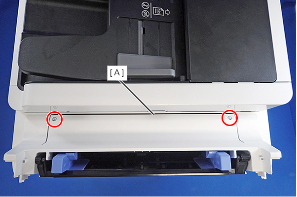
- : C.B.P-TITE-SCREW-3x10-F.ZN-3C
- Open the ADF/SCN Unit and remove the three screws that secure the Housing Left (A).
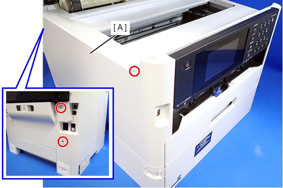
- : C.B.P-TITE-SCREW-3x10-F.ZN-3C
- Lift the Housing Left (A) to release the two hooks on the front side of the Housing Left.
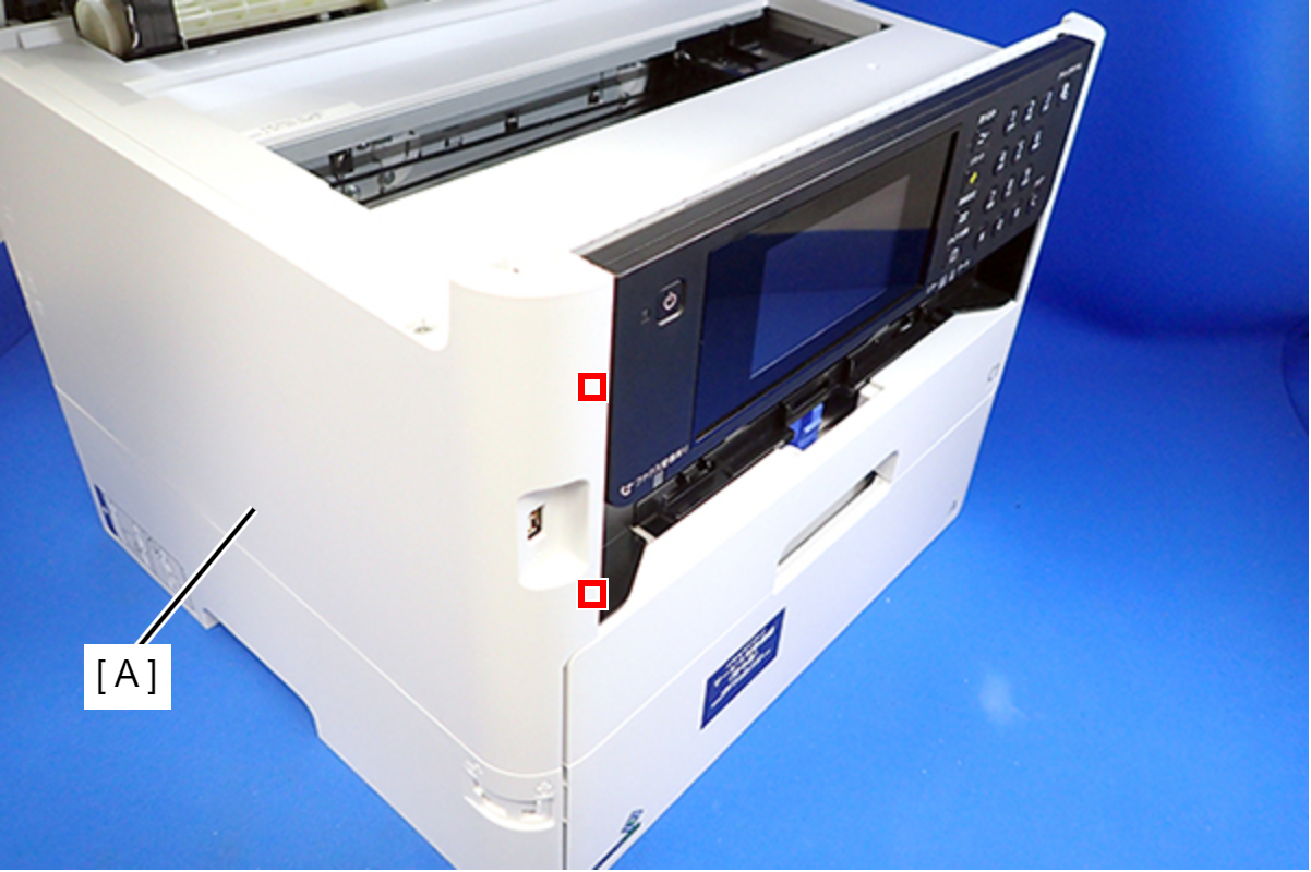
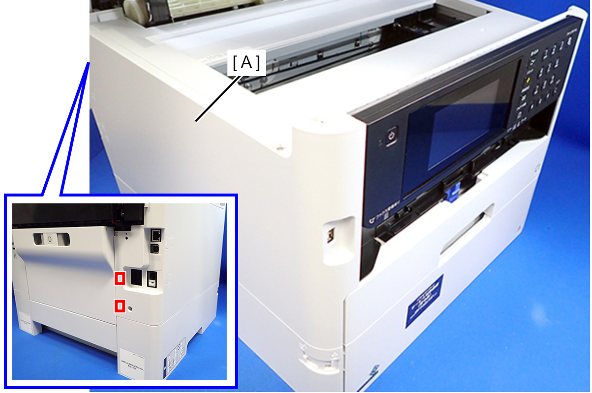
- Disengage two hooks on the rear side of the Housing Left (A), and remove the Housing Left (A).
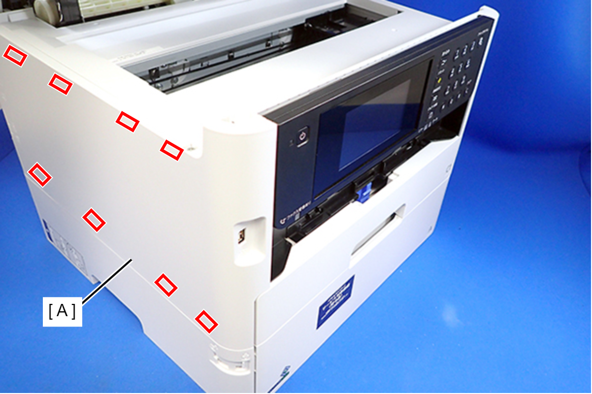
 Assembly / 組み立て
Insert the eight tabs on the Housing Left (A) to the positioning holes of the Housing Upper (B) and the RIPS Unit (C).
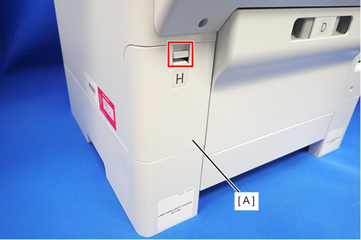
- Disengage the hook, and remove the Maintenance Box Cover (A).
- Open the ADF/SCN Unit and remove the four screws that secure the Housing Right (A).
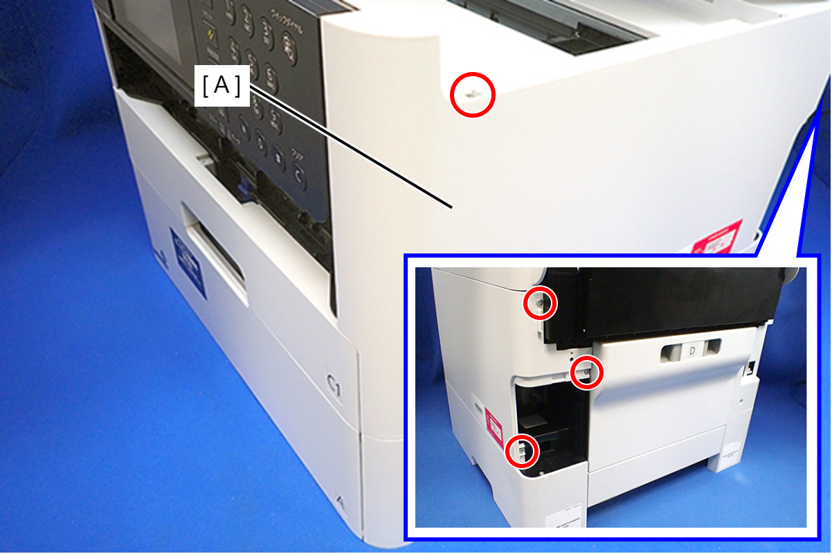
- : C.B.P-TITE-SCREW-3x10-F.ZN-3C
- Lift the Housing Right to release the two hooks on the front side of the Housing Right, then remove the Housing Right.
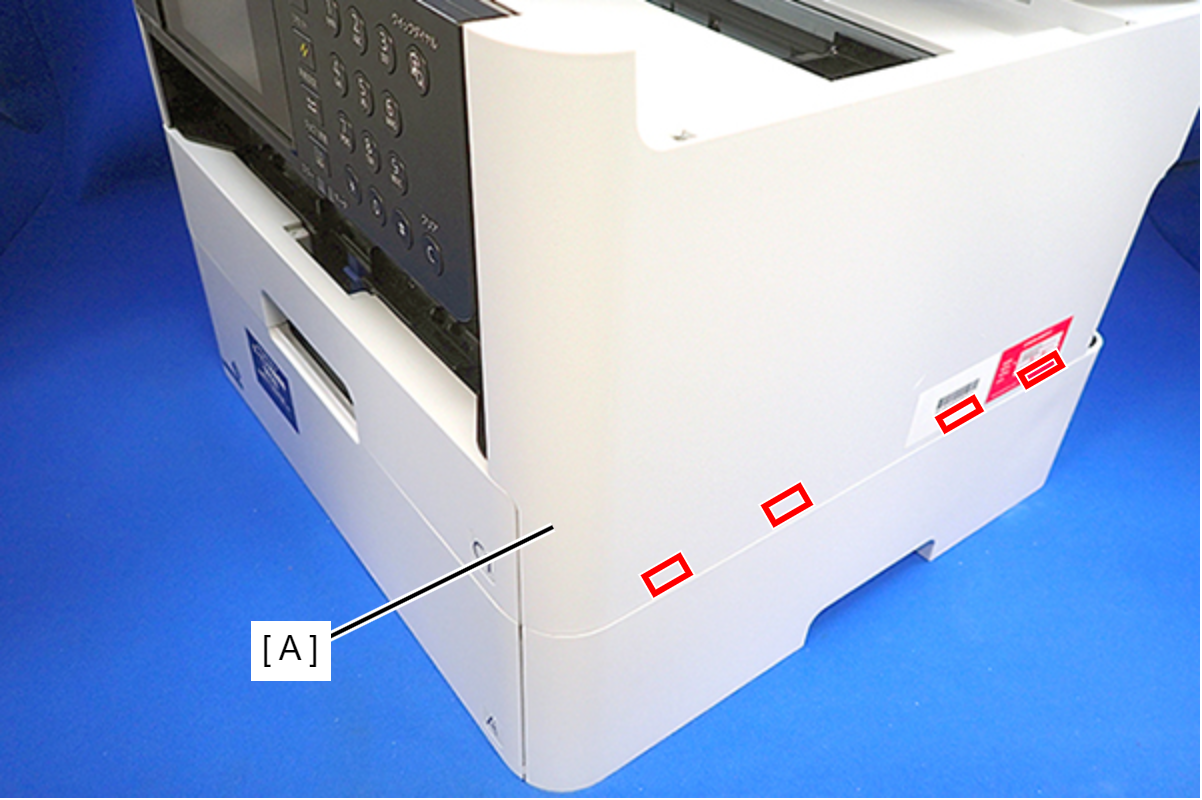
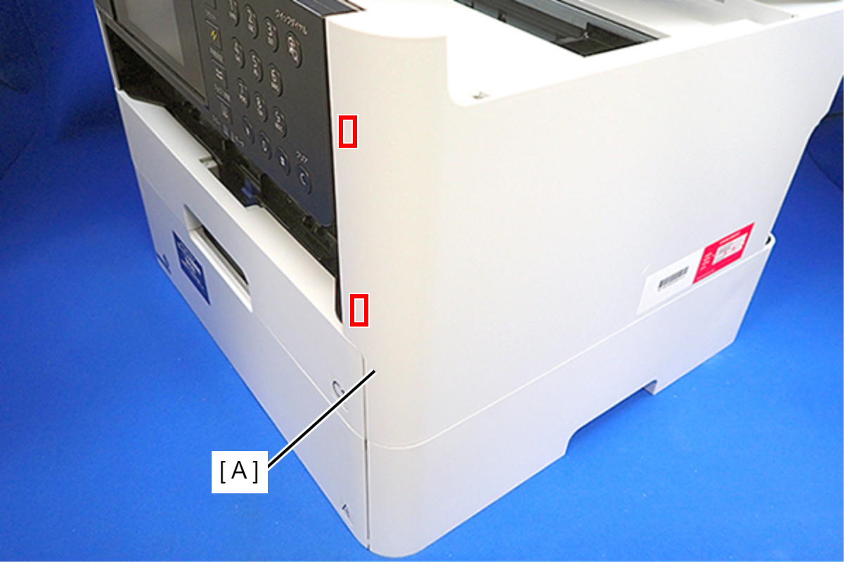 Assembly / 組み立て
Insert the four tabs of the Housing Right (A) to the positioning holes on the Ink Supply Unit.
- Remove the six screws, then remove the Housing Upper (A).
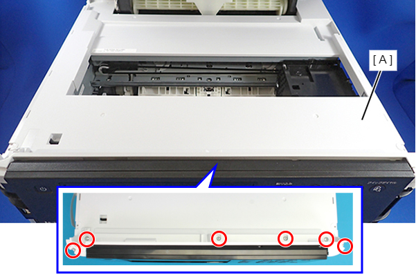
- : C.B.P-TITE-SCREW-3x10-F/ZN-3C
- Remove the two pieces of acetate tape (A), and disconnect the cable (C) from CN100 connector on the Main Board (B).
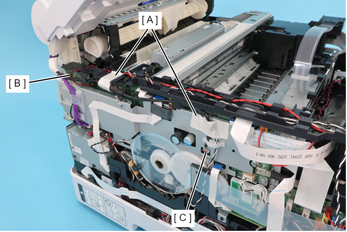
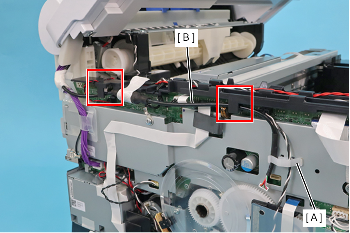
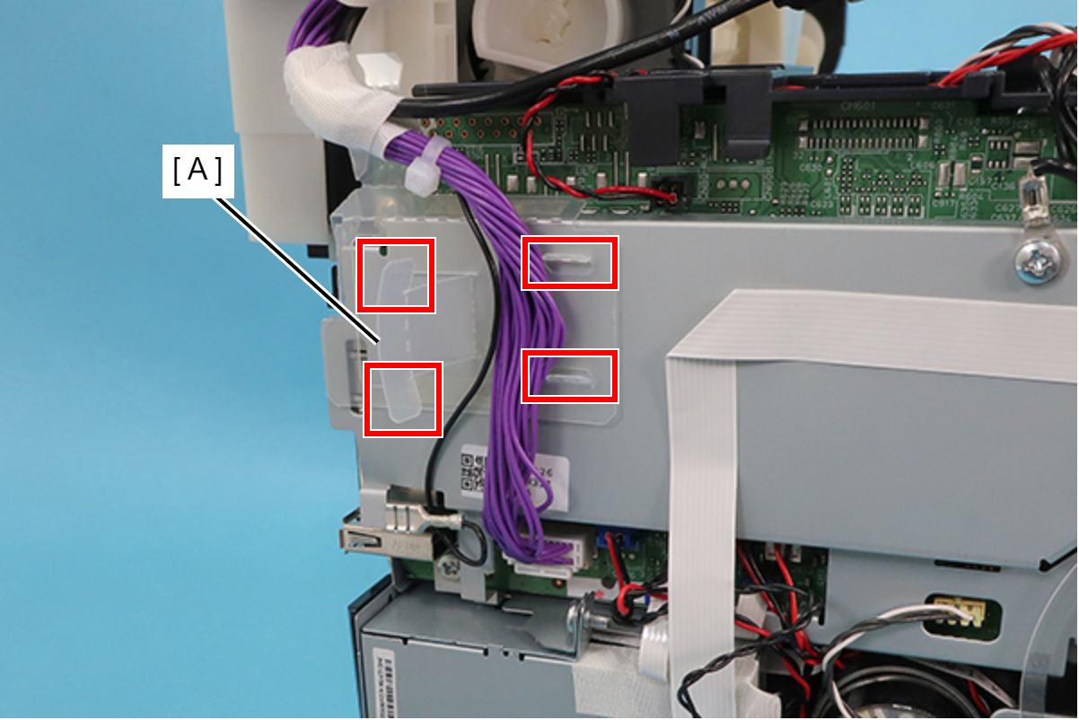
- Release the cable (B) from the two guides and the clamp (A).
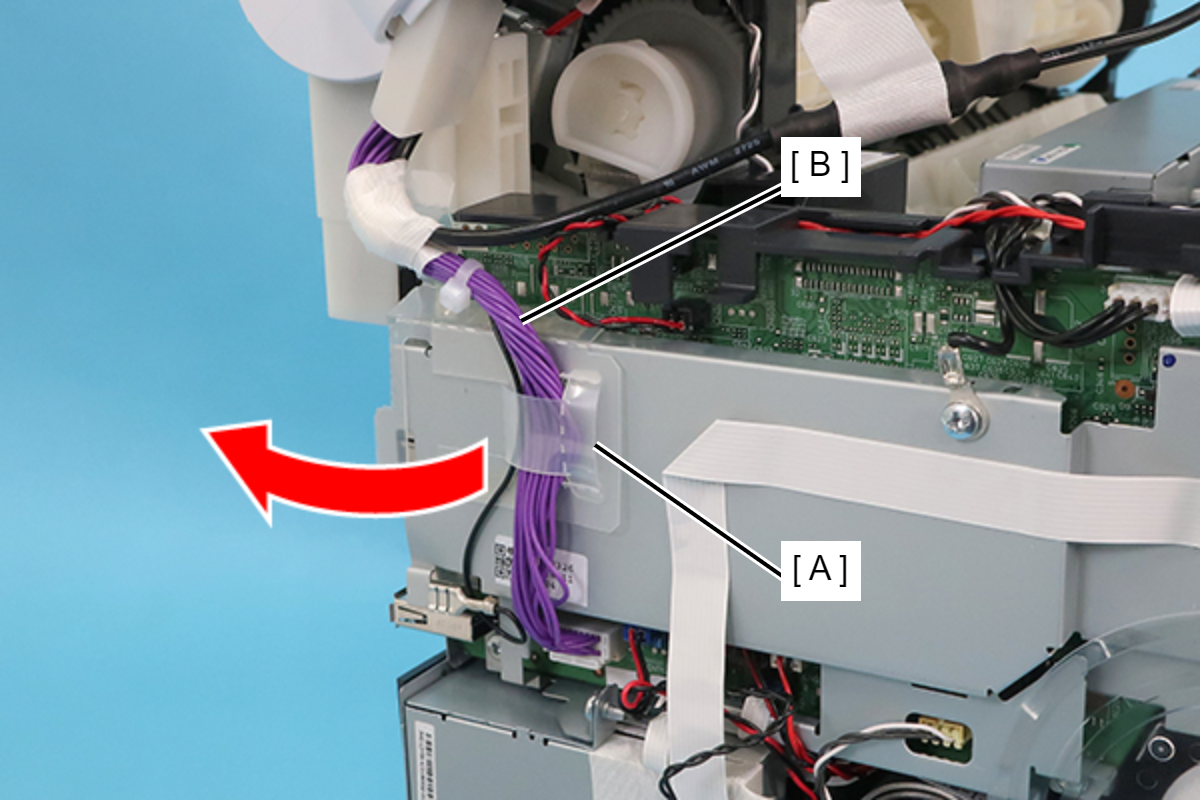
Release the cable (B) from the protective sheet (A) by opening the sheet in the direction of the arrow.
 Assembly / 組み立て
Insert the two tabs of the protective sheet (A) into the two slits respectively.
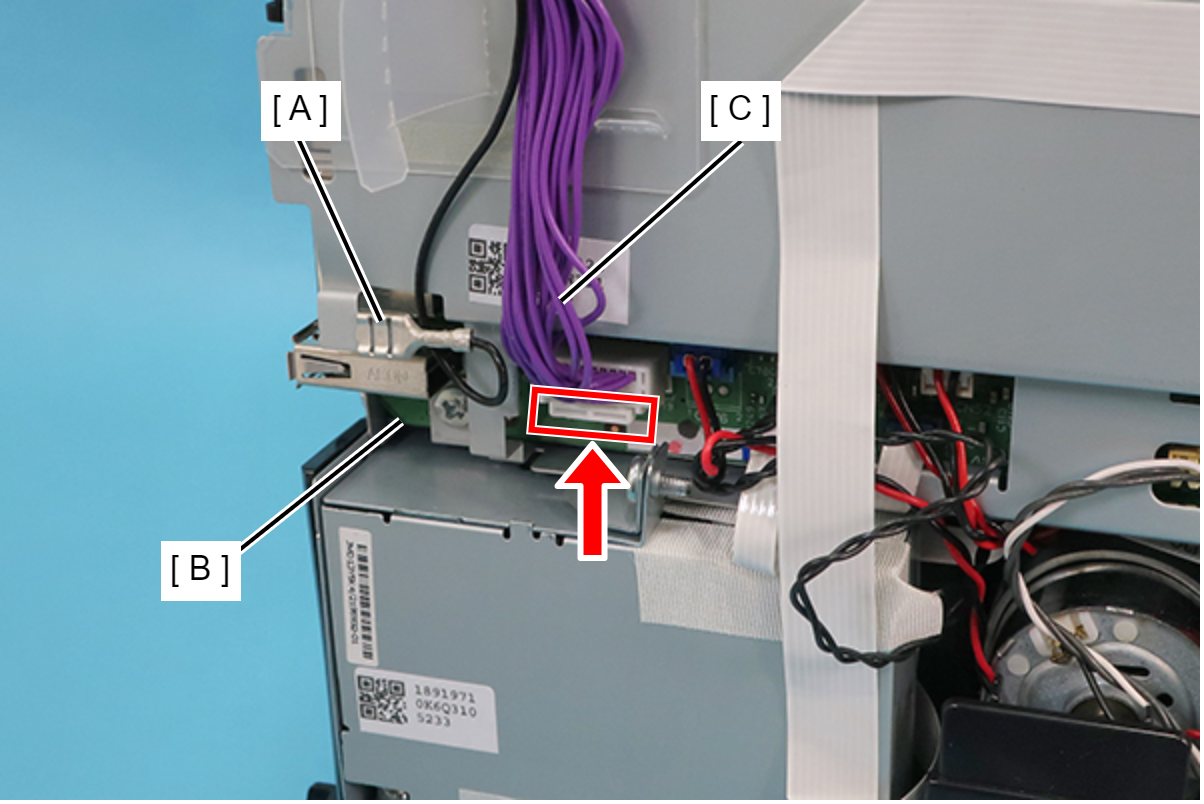
- Disconnect the ground wire (A), and while pushing the connector’s tab upward, disconnect the cable (C) from CN799 connector on the Main Board (B).
- Open the ADF/SCN Unit (A).
 Caution / 注意
- If you remove or attach the ADF/SCN Unit while it is closed, the hinge may be damaged.
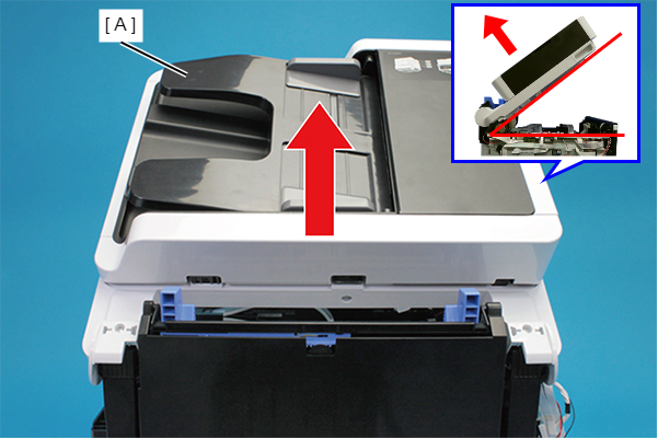
- Remove the two screws and remove the ADF/SCN Unit (A) in the direction of the arrow.
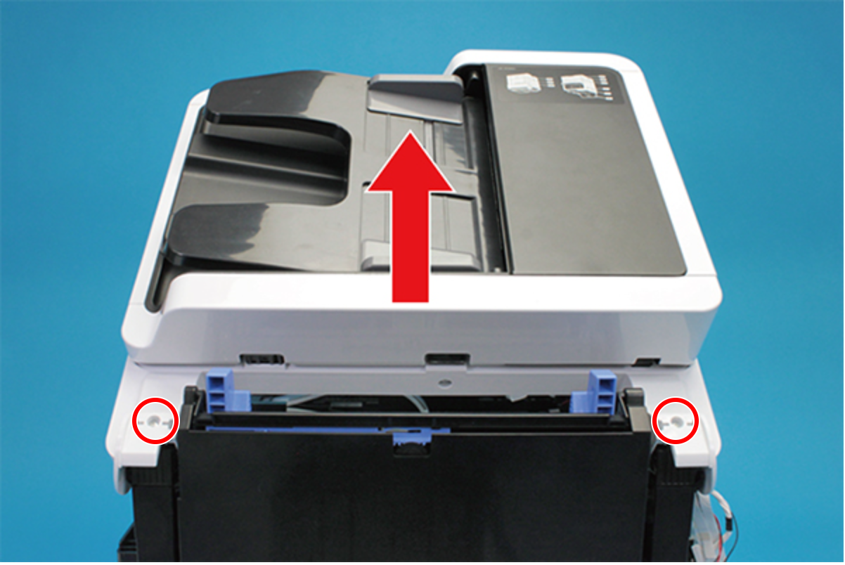
 : C.B.P-TITE-SCREW-3x10-F.ZN-3C
Assembly / 組み立て- Before screwing the ADF/SCN Unit, make sure the hinges are properly attached in place.
If the ADF/SCN Unit is opened when the hinges are NOT secured, the unit may be damaged.
- Remove the screw and then remove the Hinge Assy (Left) (A).
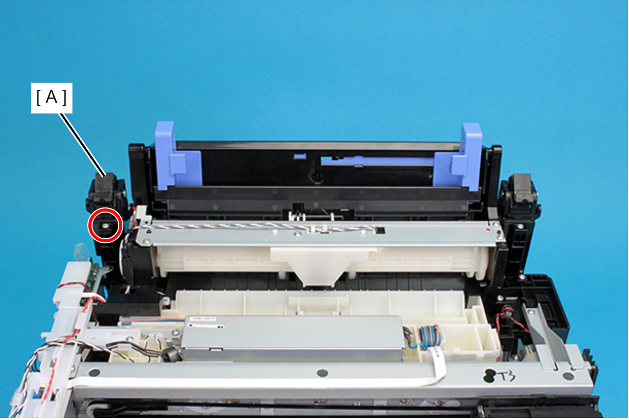
- : C.B.P-TITE-SCREW-3x10-F.ZN-3C
- Remove the three screws, and remove the Hinge Lower Cover (Left) (A).
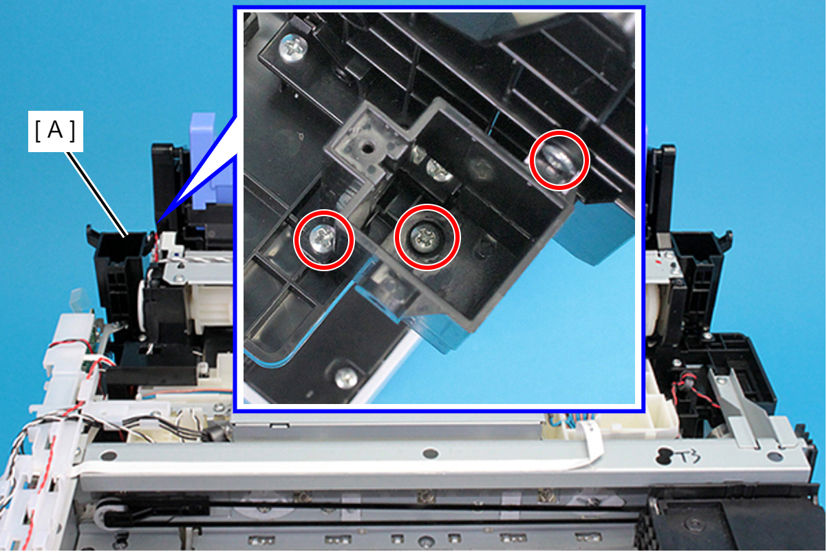
- : C.B.P-TITE-SCREW-3x10-F.ZN-3C
- Remove the screw and then remove the Hinge Assy (Right) (A).
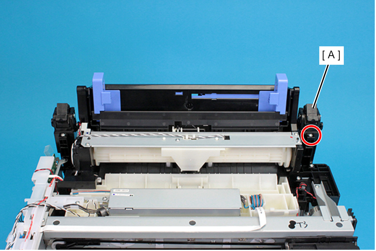
- : C.B.P-TITE-SCREW-3x10-F.ZN-3C
- Remove the three screws, and remove the Hinge Lower Cover (Right) (A).
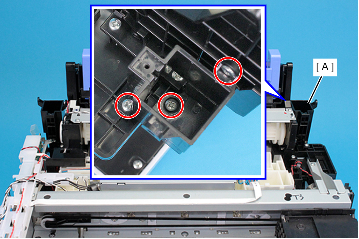
- : C.B.P-TITE-SCREW-3x10-F.ZN-3C
- Remove the two screws securing the Cable Guide (A).
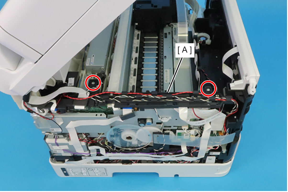
- : C.B.P-TITE-SCREW-3x10-F.ZN-3C
 Check Point / チェックポイント
When removing the screws, if the screwdriver interferes with the ADF/SCN Unit, use a stubby screwdriver.
- Peel off the CRCM FFC (B) from the CRCM FFC Sheet (A).
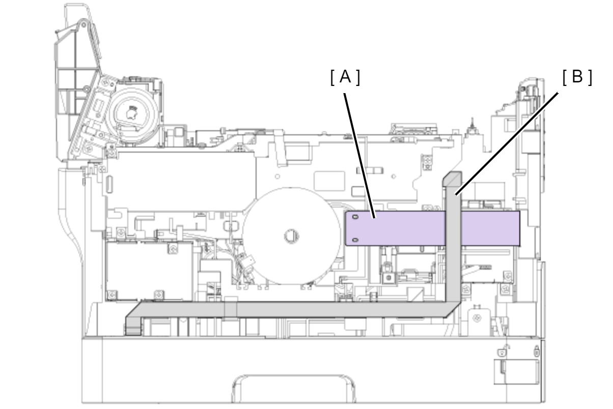
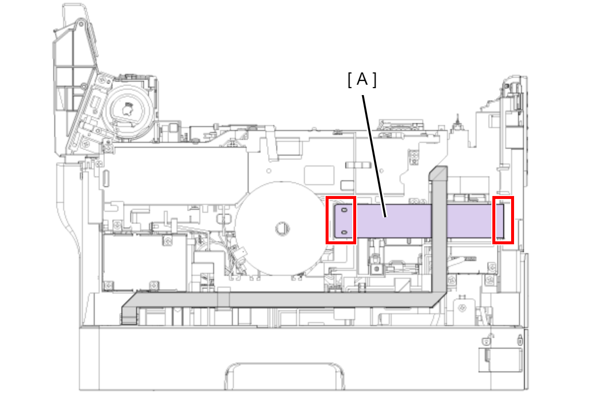
- Peel off the double-sided tape at two locations and then remove the CRCM FFC Sheet (A).
- Disconnect the cables (B) from the connector (CN20, CN51, CN56) of the Relay Board (A).
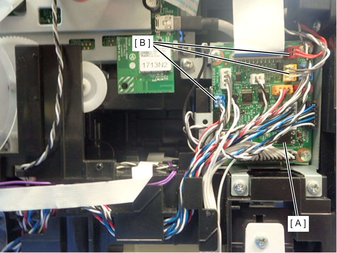
- Remove the acetate tape (A), and release the cable (B) from the two guides.
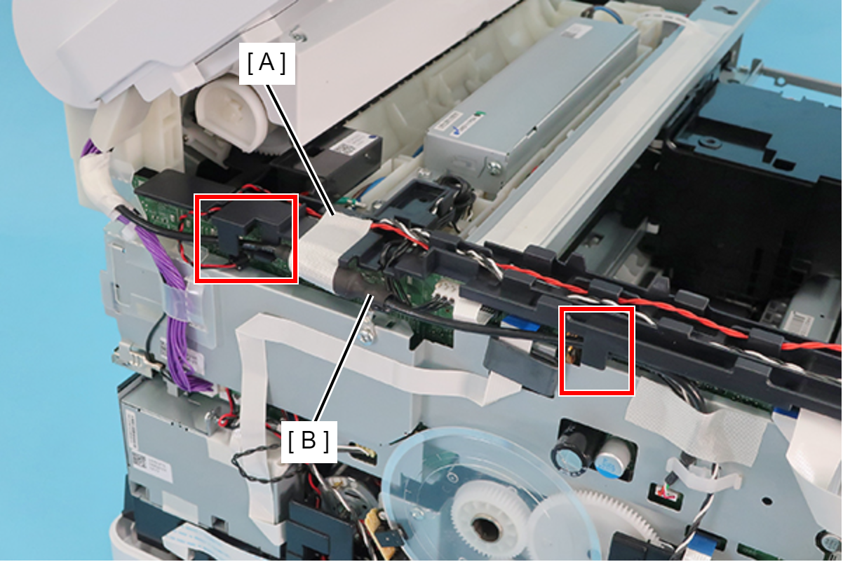
- Disconnect the two cables (B) from the connectors (CN74, CN80) of the Main Board (A).
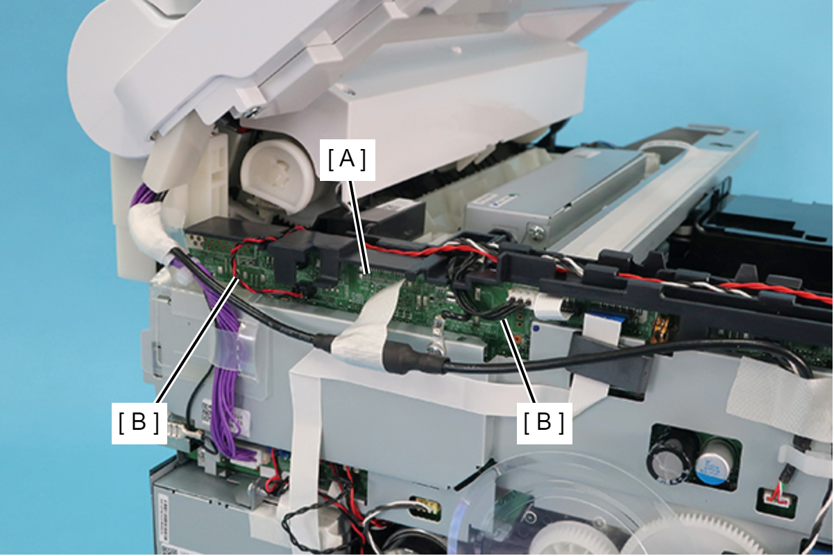
- Remove the two screws, and release the ground wire (A) from the slit to remove it.
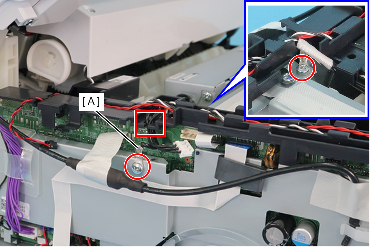
- : C.B.S-TITE-SCREW-3x6-F.ZN-3C
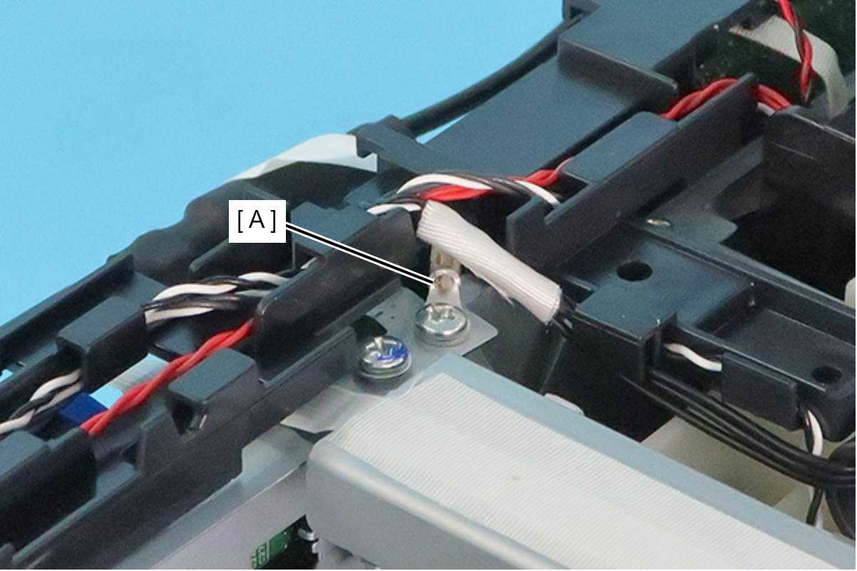
Assembly / 組み立てAttach the ground wire with the terminal (A) oriented as shown below.
- Move the Cable Guide as shown below.
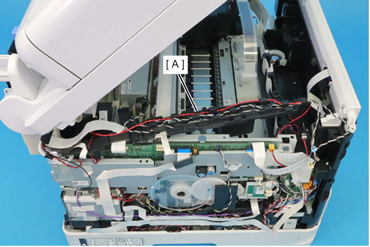
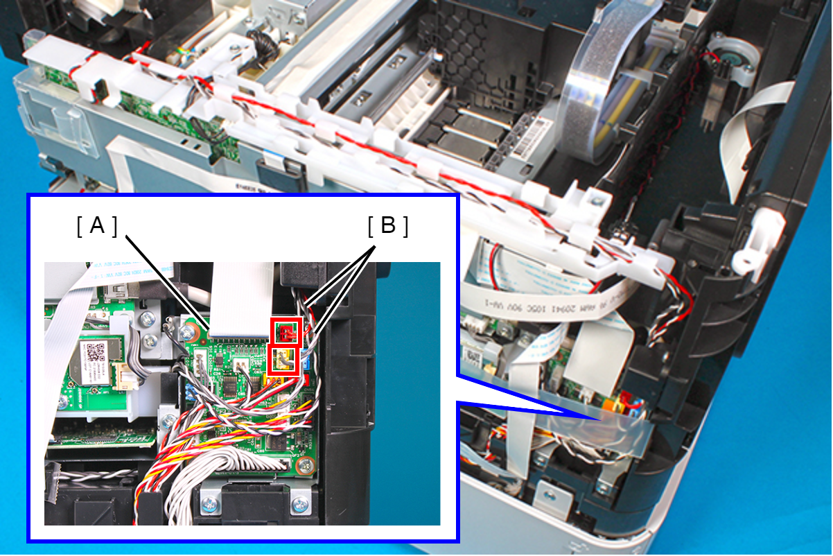
- Disconnect the cables (B) from the connectors (CN51, CN56) on the Relay Board (A).
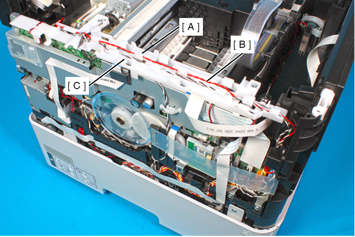
Release the solenoid cable (B) and Rear ASF Paper Detection Sensor cable (C) from the Cable Guide (A).
 Assembly / 組み立て
- Route the solenoid cable (A) through the five hooks on the Cable Guide (B).
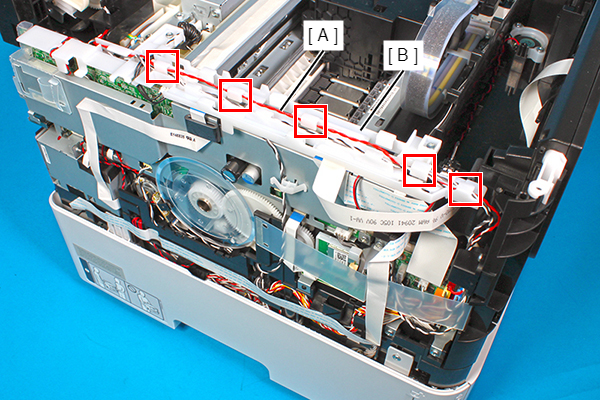
- Route the Rear ASF Paper Detection Sensor cable (A) through the three hooks on the Cable Guide (B).
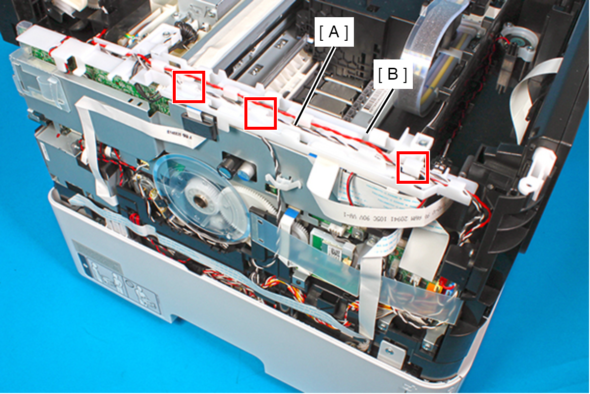
- Route the solenoid cable (A) through the five hooks on the Cable Guide (B).
Remove the four screws and then remove the Rear ASF Unit (A).
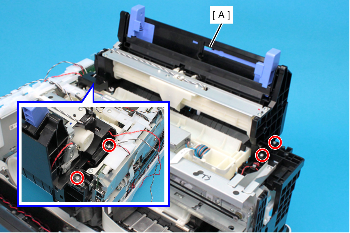
- : C.B.P-TITE-SCREW-3x10-F.ZN-3C
- Remove the two screws, then remove the PS Ground Plate (A).
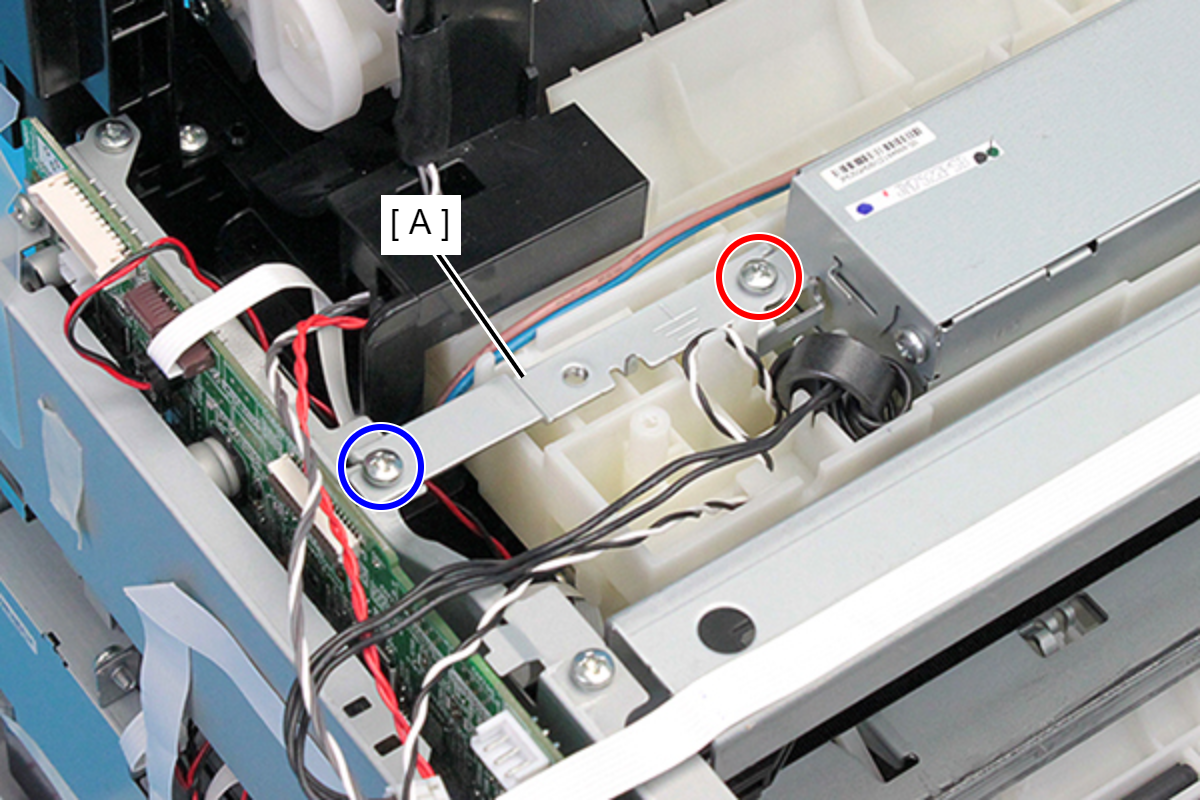
- : C.B.P-TITE-SCREW-3x10-F.ZN-3C
 : C.B.S-TITE-SCREW-3x6-F.ZN-3C
Assembly / 組み立てAssemble ensuring that screw types are correct.
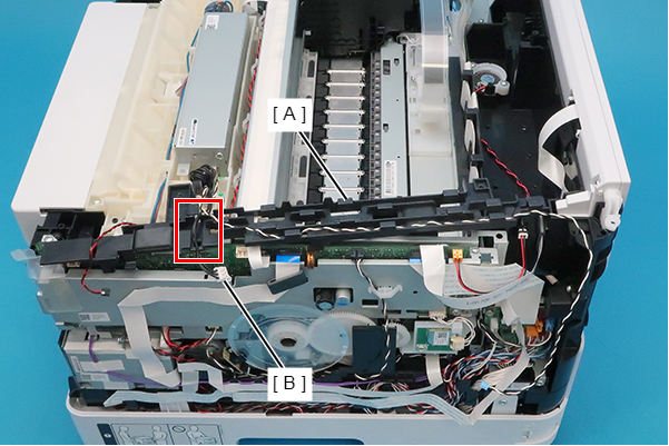
- Release the Rear ASF Sensor cable (B) from the three hooks of the Cable Guide (A).
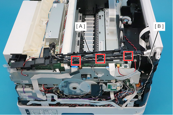
- Release the cables (B) from the slit of the Cable Guide (B).
- Remove the screw securing the AC Inlet (A).
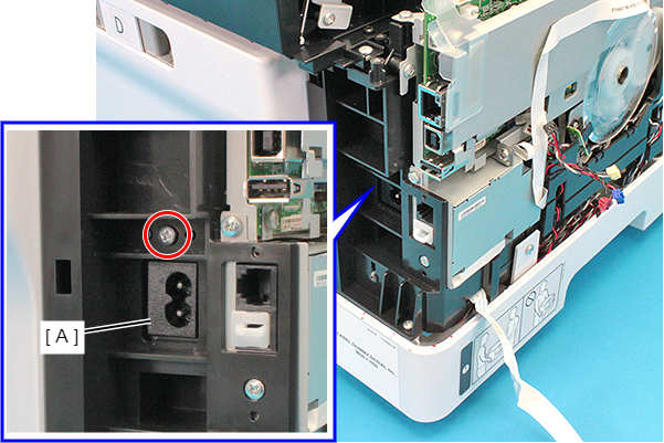
- : C.B.P-TITE-SCREW-3x10-F.ZN-3C
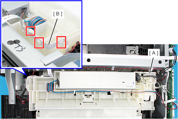
- Release the FFC (B) from three hooks on the Rear ASF Upper Guide Assy (A).
- Remove the four screws, then remove the Rear ASF Upper Guide Assy (A).
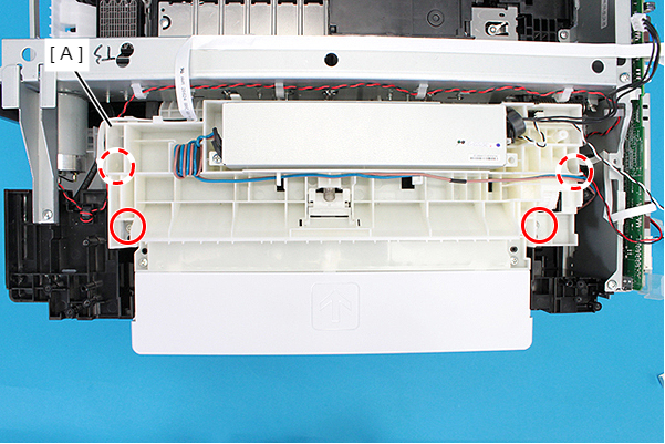
- : C.B.P-TITE-SCREW-3x10-F.ZN-3C
Assembly / 組み立てFirst, insert the AC inlet (A) into the hole.
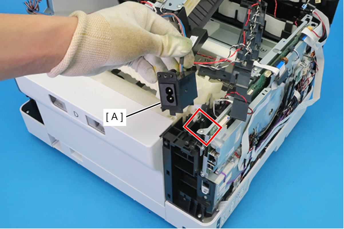
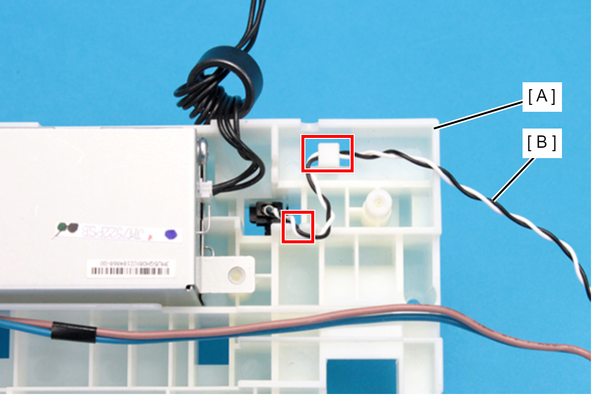
- Release the cable (B) from the hook and slit on the Rear ASF Upper Guide Assy (A).
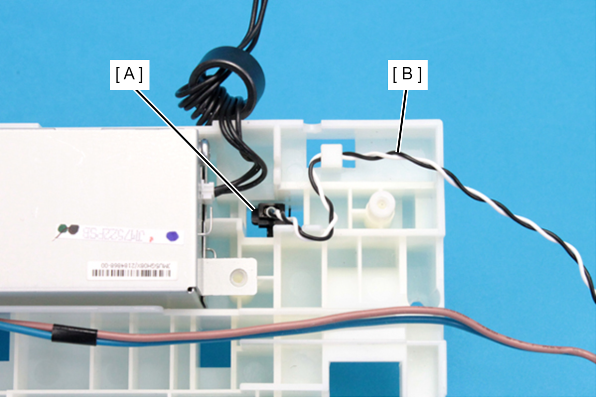
- Disconnect the cable (B) from the connector of the Rear Unit Detection Sensor (A).
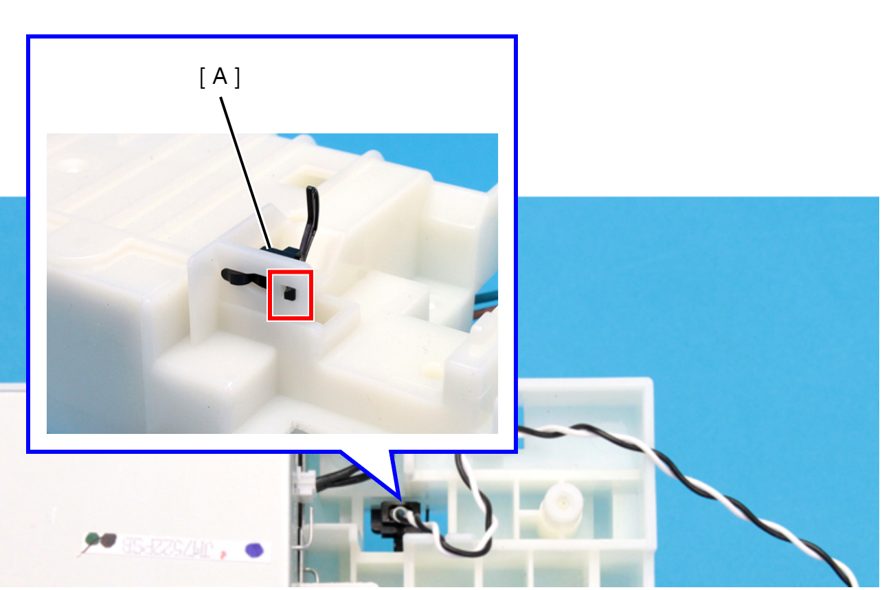
- Disengage hook by pushing up the sensor (A).
 Caution / 注意
The length of the two hooks on the Rear Unit Detection Sensor (A) differs. When removing it, disengage the shorter hook (B).