
Ink System Unit (EP-C800 Series)
 Adjustment / 調整 Adjustment / 調整 |
When replacing this part, you need to run the menu from the service support mode before replacing it. |
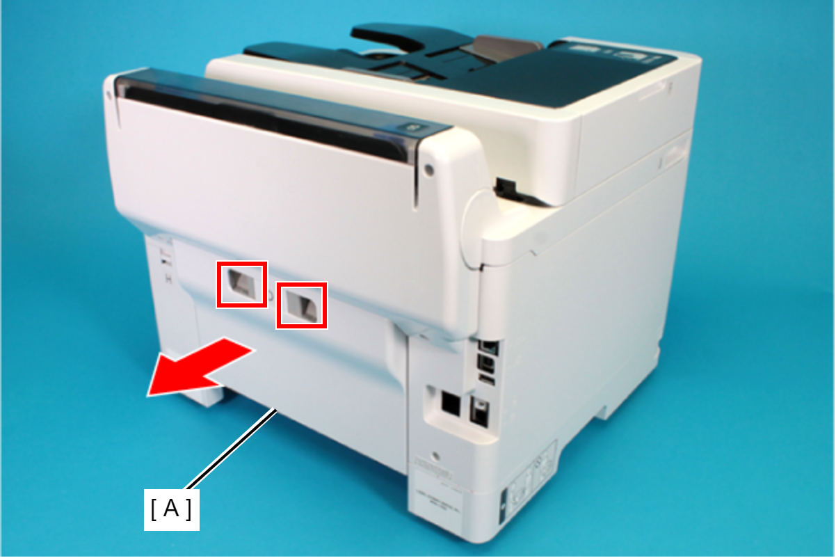
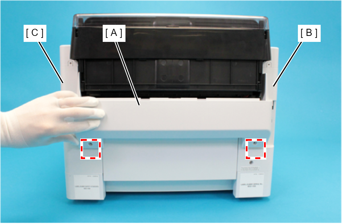
- Remove the Rear Unit (A) in the direction of the arrow while pressing the buttons inward.
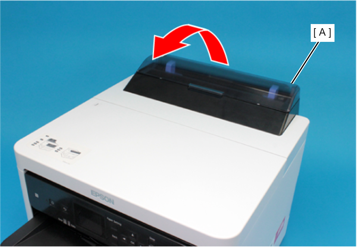
- Open the ASF Cover (A) and remove the two screws securing the Rear Housing Assy (B).
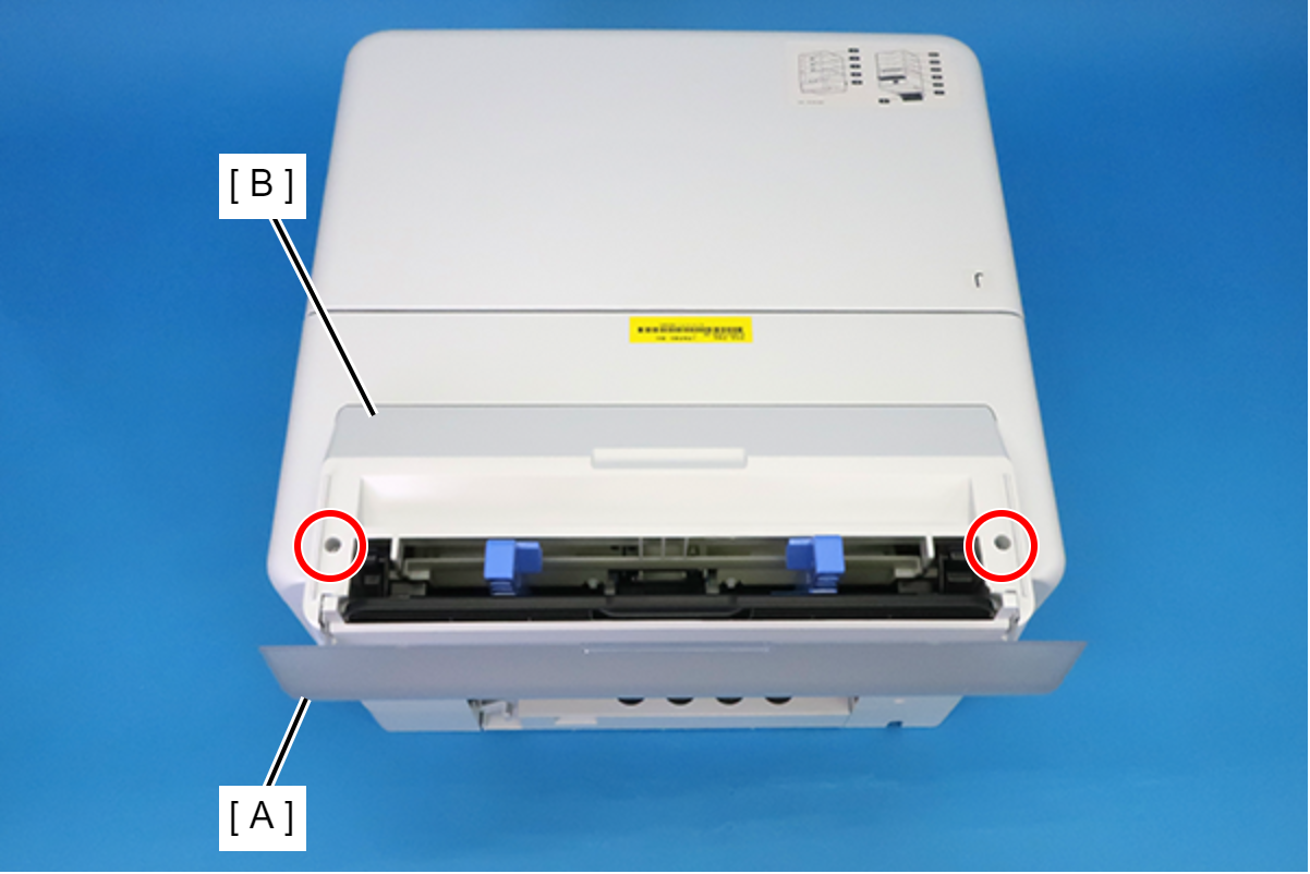
 : C.B.P-TITE-SCREW-3x10-F.ZB-3C
- Remove the four screws that secure the Rear Back Cover (A).
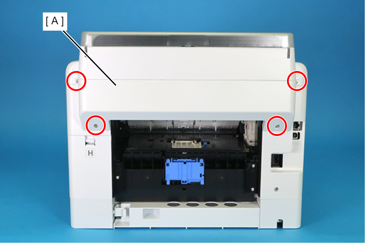
 : C.B.P-TITE-SCREW-3x10-F.ZN-3C
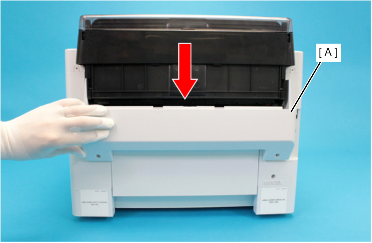
- Remove the Rear Back Cover (A) downward.
 Assembly / 組み立て
Attach the two dowels of the Rear Back Cover (A) to the positioning holes on the Housing Left (B) and the Housing Right (C).
- Remove the Rear Upper Cover Assy (A) in the direction of the arrow.
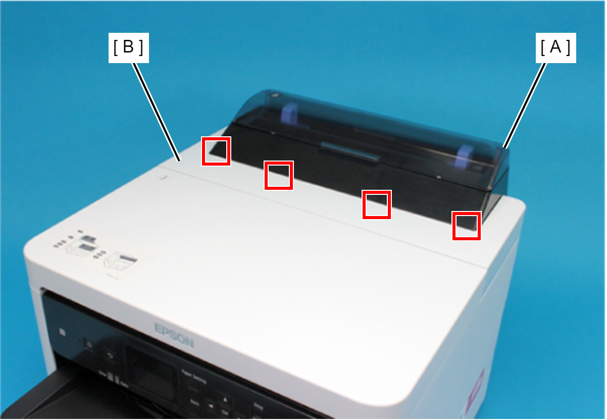
 Assembly / 組み立て
Insert the four tabs of the Rear Upper Cover Assy (A) to the positioning holes of the Housing ASF (B).
- Remove the two screws securing the Housing ASF (A).
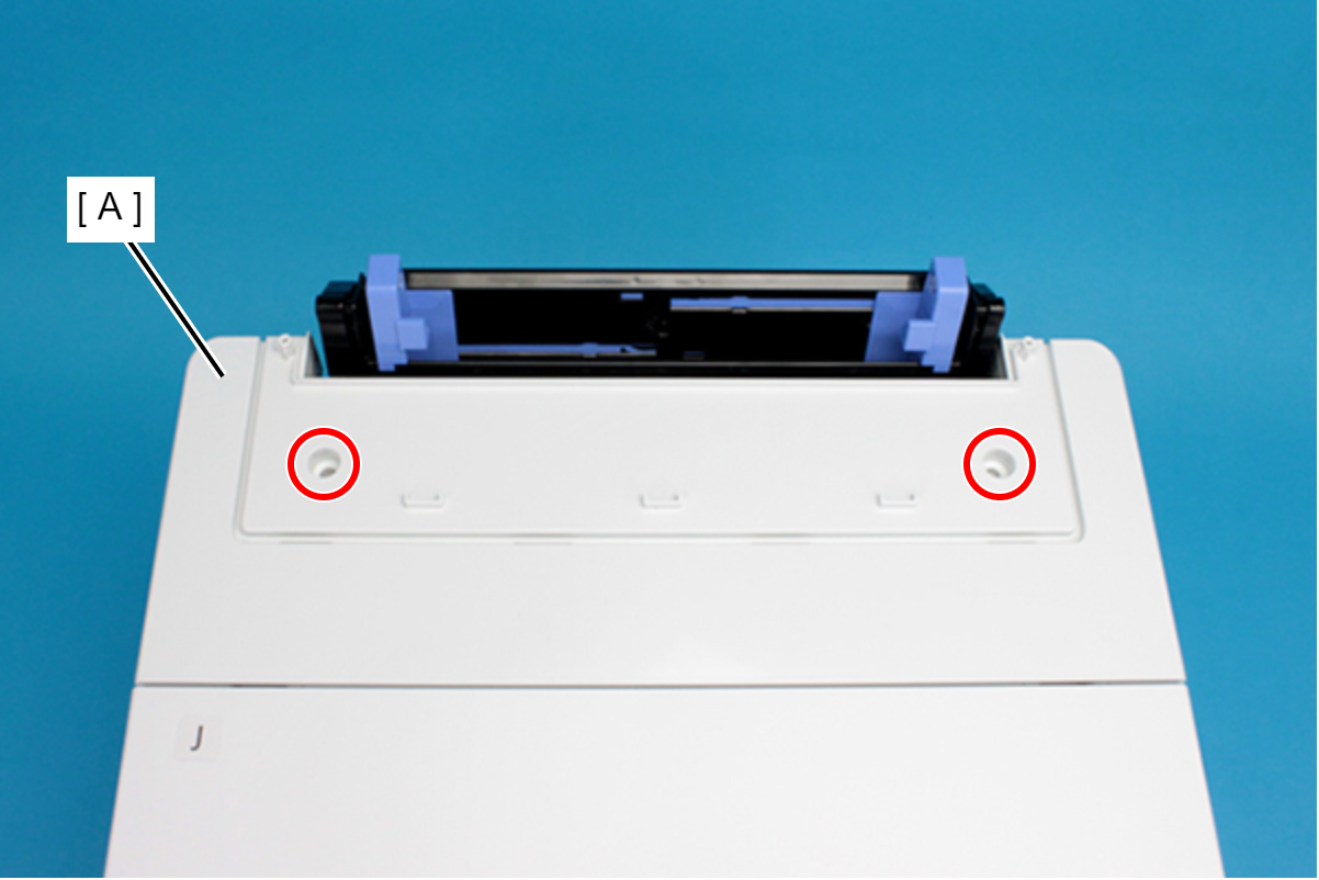
- : C.B.P-TITE-SCREW-3x10-F.ZN-3C
- Open the Printer Cover (A) and remove the four screws, and then remove the Housing ASF (B).
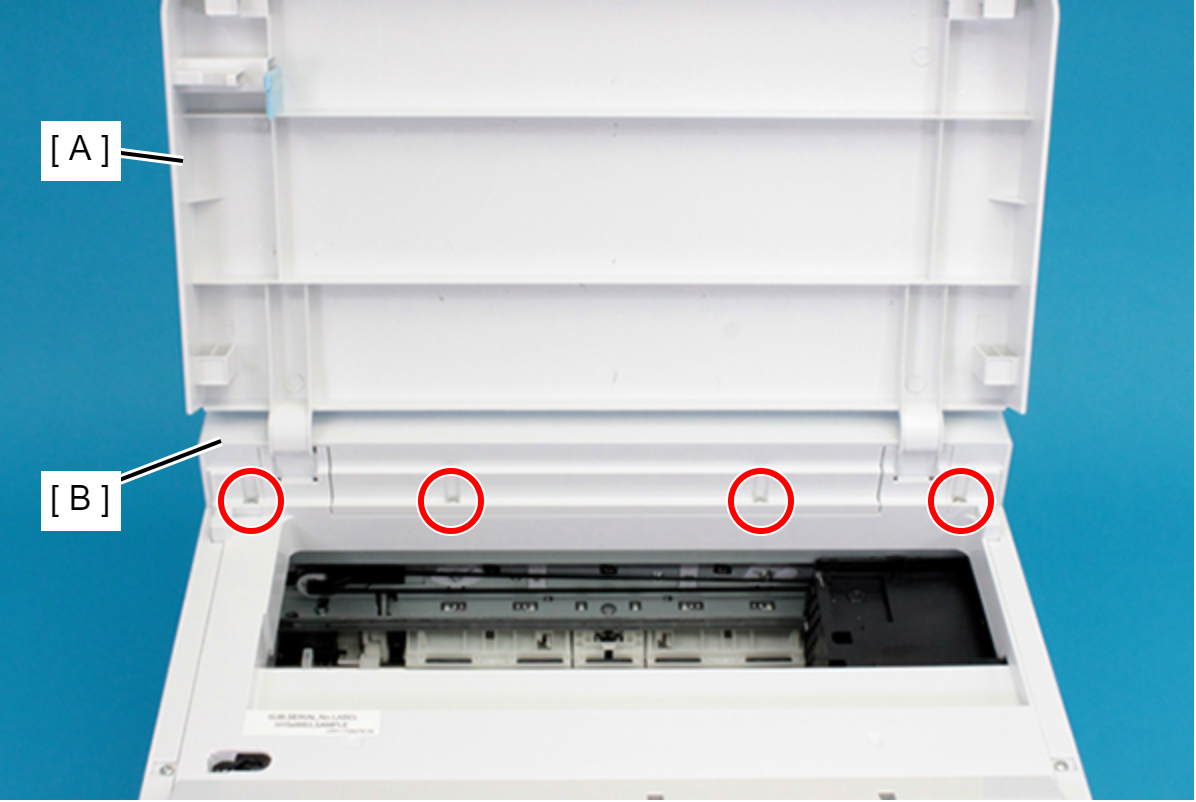
- : C.B.P-TITE-SCREW-3x10-F.ZN-3C
- Remove the Printer Cover (A) upward.
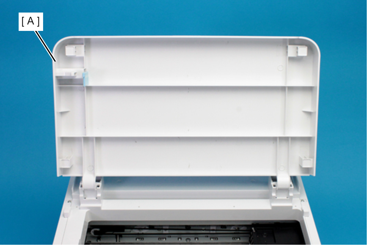
- Remove the three screws that secure the Housing Left (A).
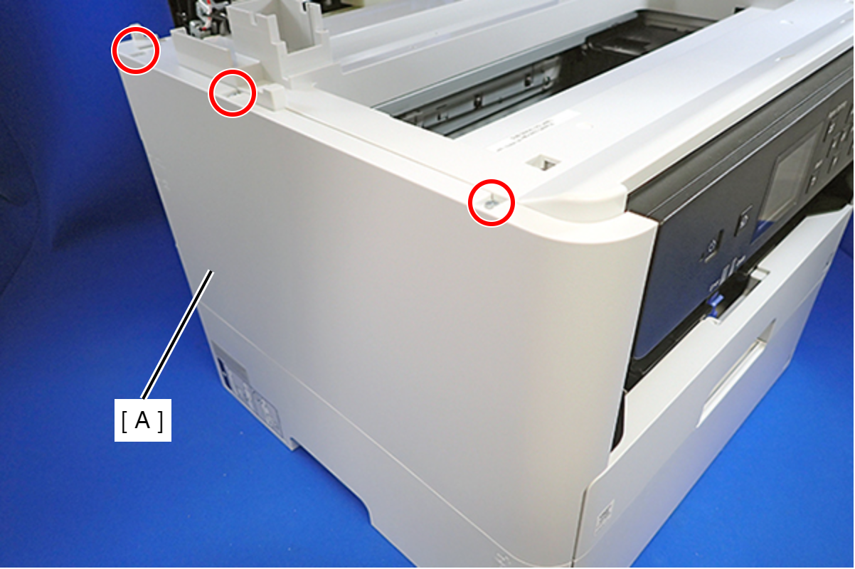
- : C.B.P-TITE-SCREW-3x10-F.ZN-3C
- Remove the two screws that secure the Housing Left (A).
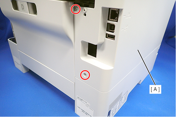
- : C.B.P-TITE-SCREW-3x10-F.ZN-3C
- Lift the Housing Left (A) to release the two hooks each on the front side and rear side of the Housing Left (A), and then remove the Housing Left (A).
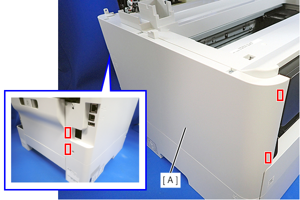
Assembly / 組み立てInsert the four tabs on the Housing Left (A) to the positioning holes of the Ink Supply Unit (B).
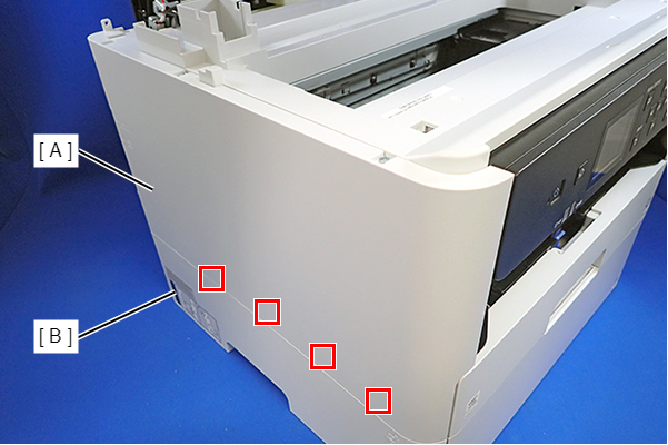
- Disengage the hook, and remove the Maintenance Box Cover (A).
- Remove the three screws that secure the Housing Right (A).
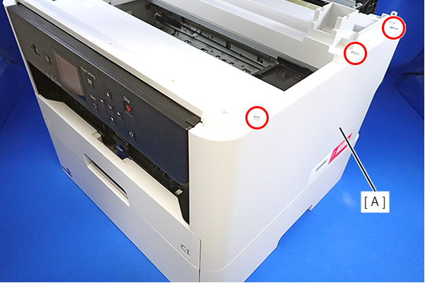
 : C.B.P-TITE-SCREW-3x10-F.ZN-3C
- Remove the two screws that secure the Housing Right (A).
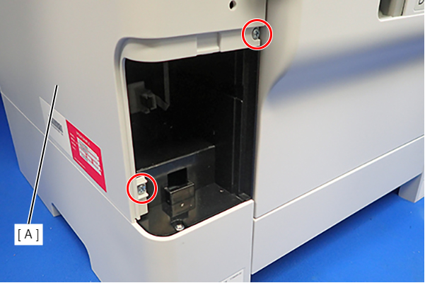
- : C.B.P-TITE-SCREW-3x10-F.ZN-3C
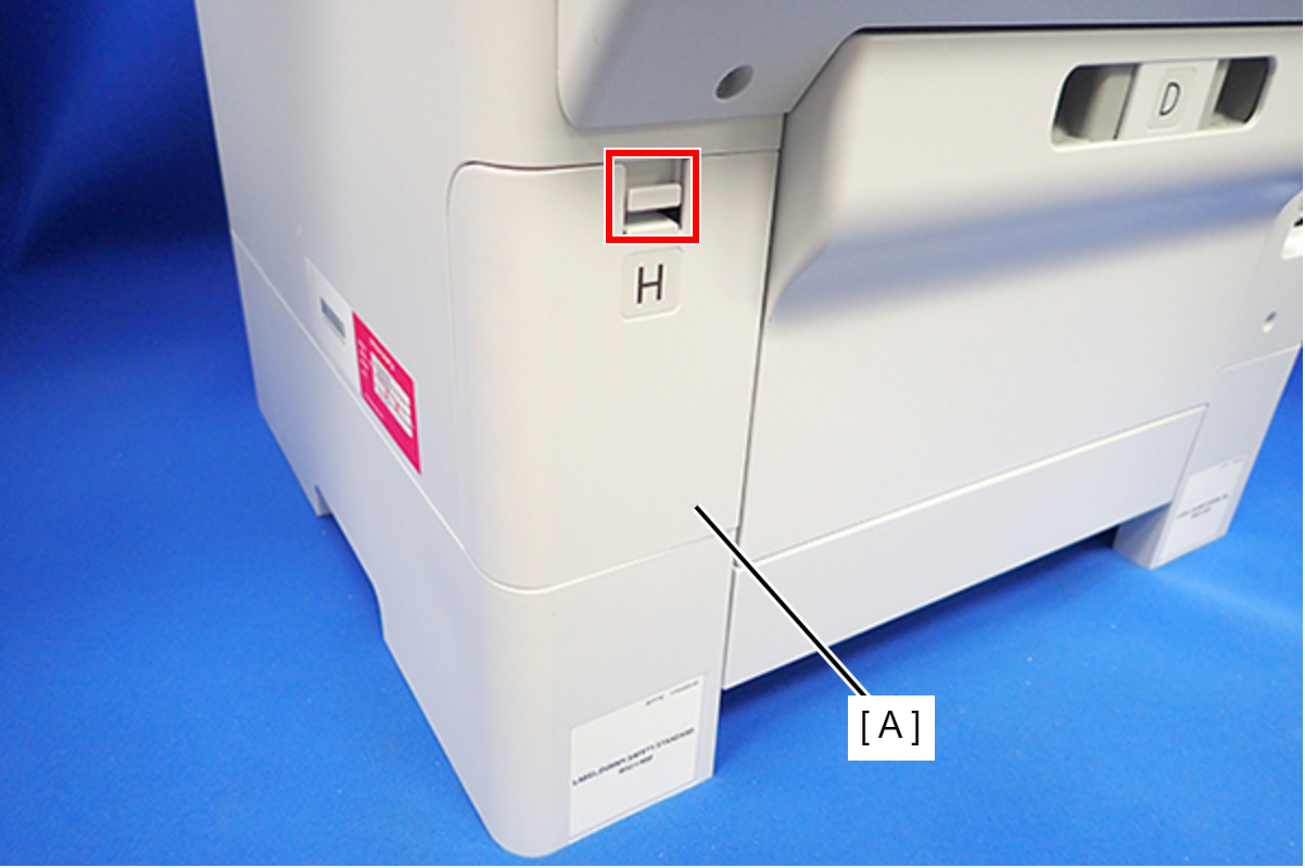
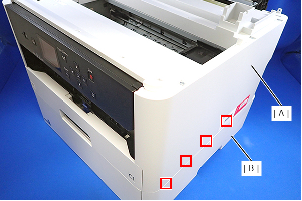
- Lift the Housing Right (A) to release the two hooks on the front side of the Housing Right (A), then remove the Housing Right (A).

Assembly / 組み立てInsert the four tabs of the Housing Right (A) to the positioning holes on the Ink Supply Unit (B).
- Remove the seven screws and remove the Housing Top (A).
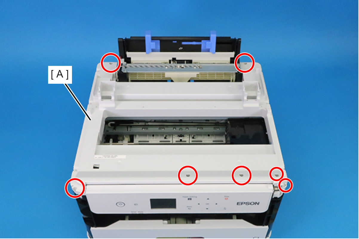
- : C.B.P-TITE-SCREW-3x10-F.ZN-3C
Remove the two screw that secure the Ink Supply Tube (A).
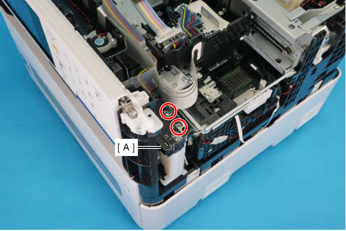
- : C.B.P-TITE-SCREW-2.5x6-F.ZN-3C
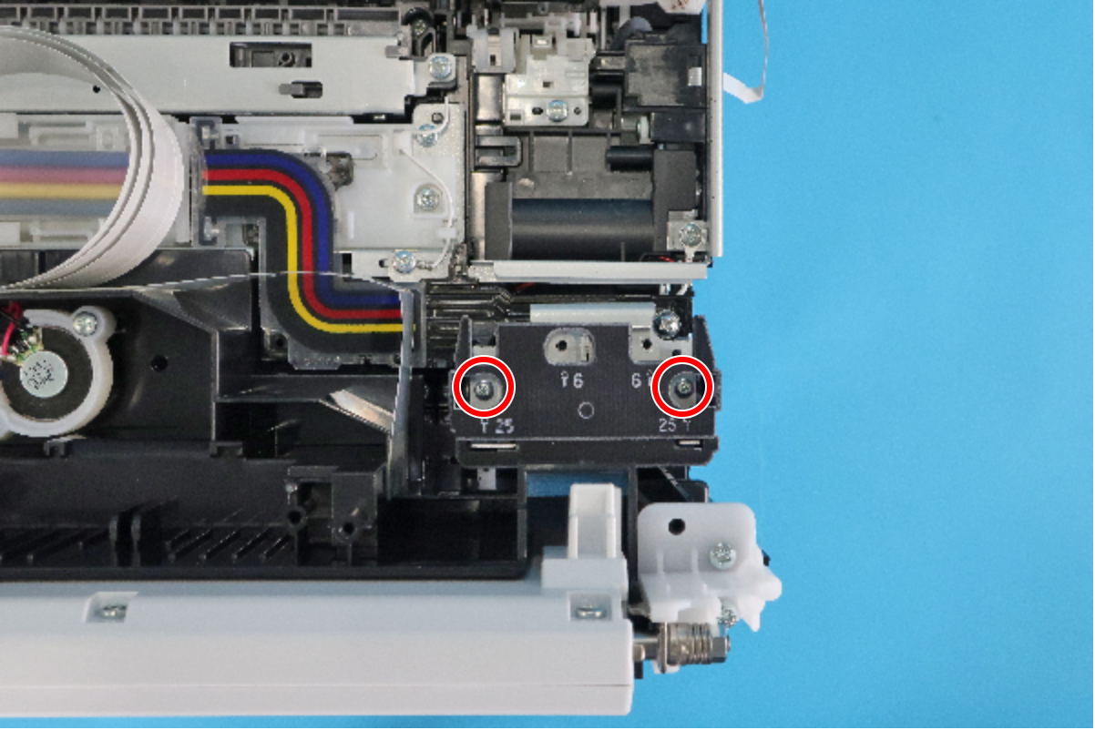
Remove the two Bind Screw2.5 x 25 (w/washer).
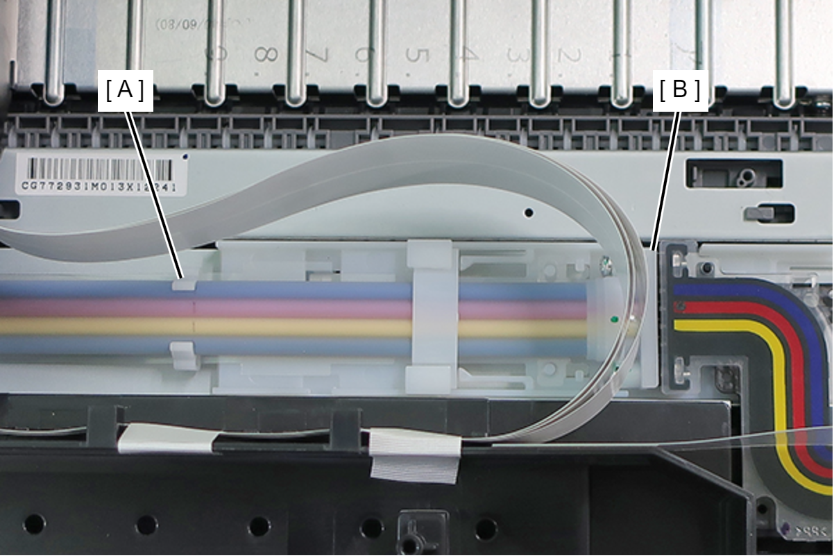
- Remove the Ink Tube (B) from the Tube Clamp (A).
 Assembly / 組み立て
- At the marking point on the Ink Supply Tube (A), attach the Ink Supply Tube (A) to the Tube Clamp (B).
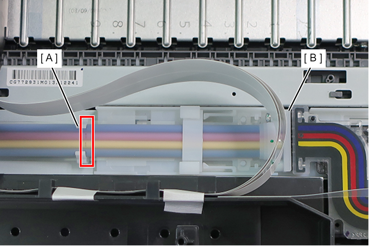
- If the marking is not visible, refer to the figure below.
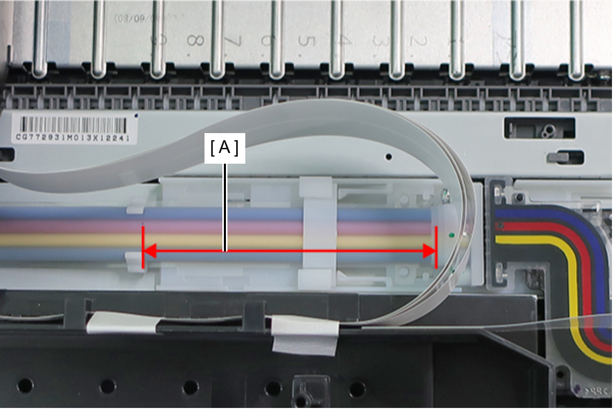
- Length of (A): 87.5 ± 1 mm
- At the marking point on the Ink Supply Tube (A), attach the Ink Supply Tube (A) to the Tube Clamp (B).
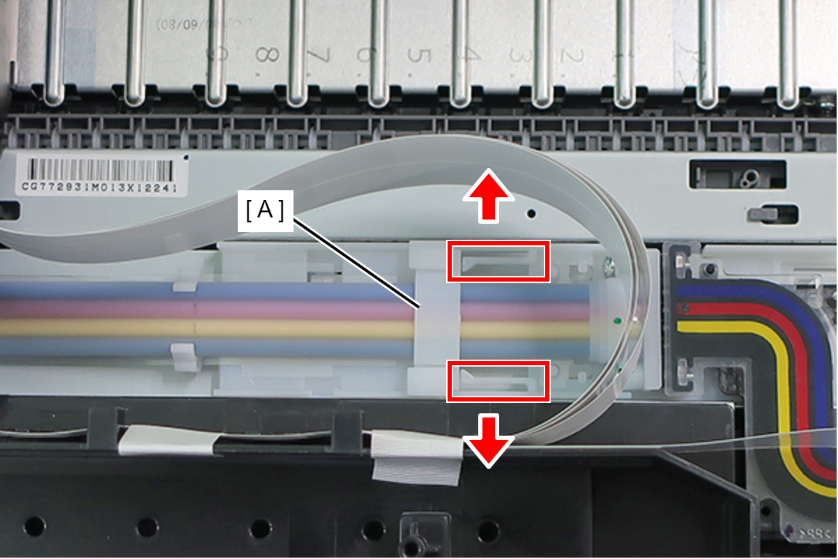
- Remove the Tube Holder (A) while pressing the two hooks outward.
- Remove the screw that secure the Ink Supply Tube (A).
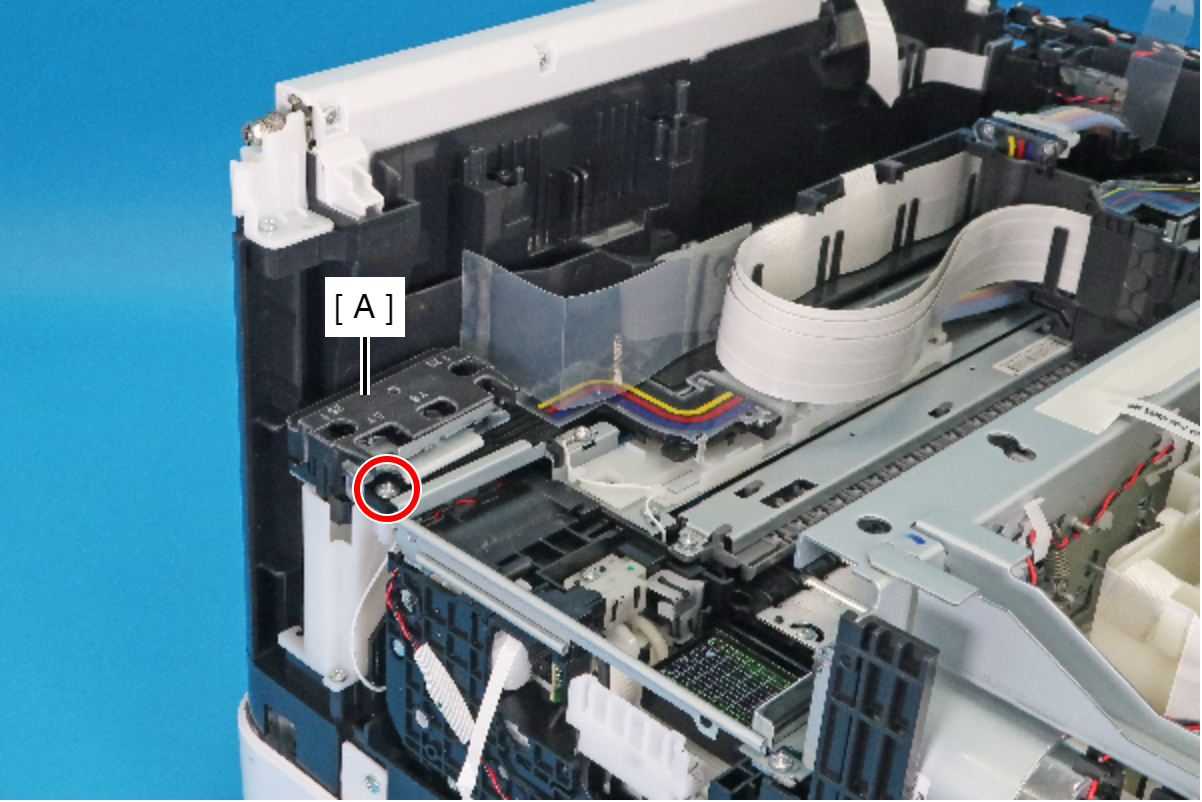
- : C.C.P-TITE-SCREW-3x12-F.ZN-3C / C.C.P-TITE-SCREW-3x14-F.ZN-3C
- Peel off the two-sided tape fixing the film (A).
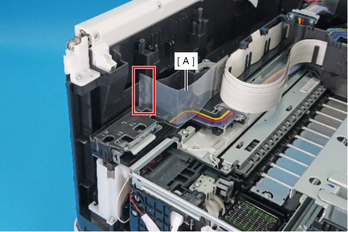
 Caution / 注意
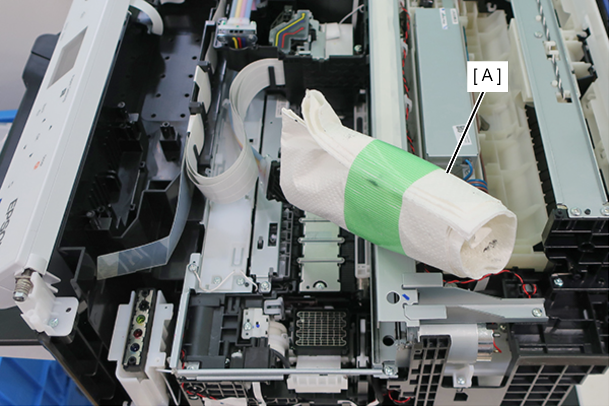
In the following steps, ink may spill from the Ink Supply Tube. Prepare waste cloths or similar in advance.
- While avoiding Film (A) remove the Ink Feed Tube (B) in the direction of the arrow.
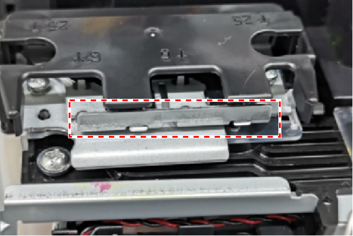
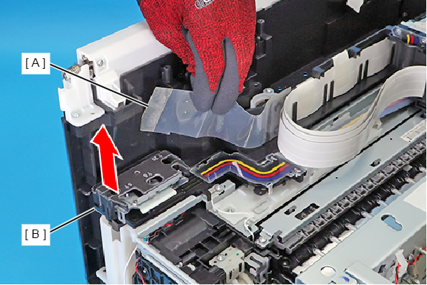 Caution / 注意
Never lift the part indicated by the red frame in the figure below, as ink may leak out.
 Check Point / チェックポイント
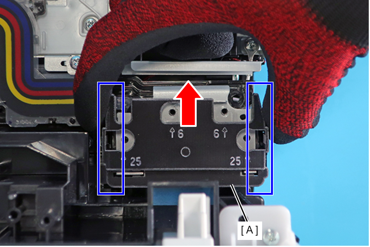
When removing the Ink Supply Tube, be careful of the following points.
- Always hold the Ink Supply Tube only by the parts on its end (A), which are indicated in the blue frames.
- Pull the end (A) of the Ink Supply Tube straight up.
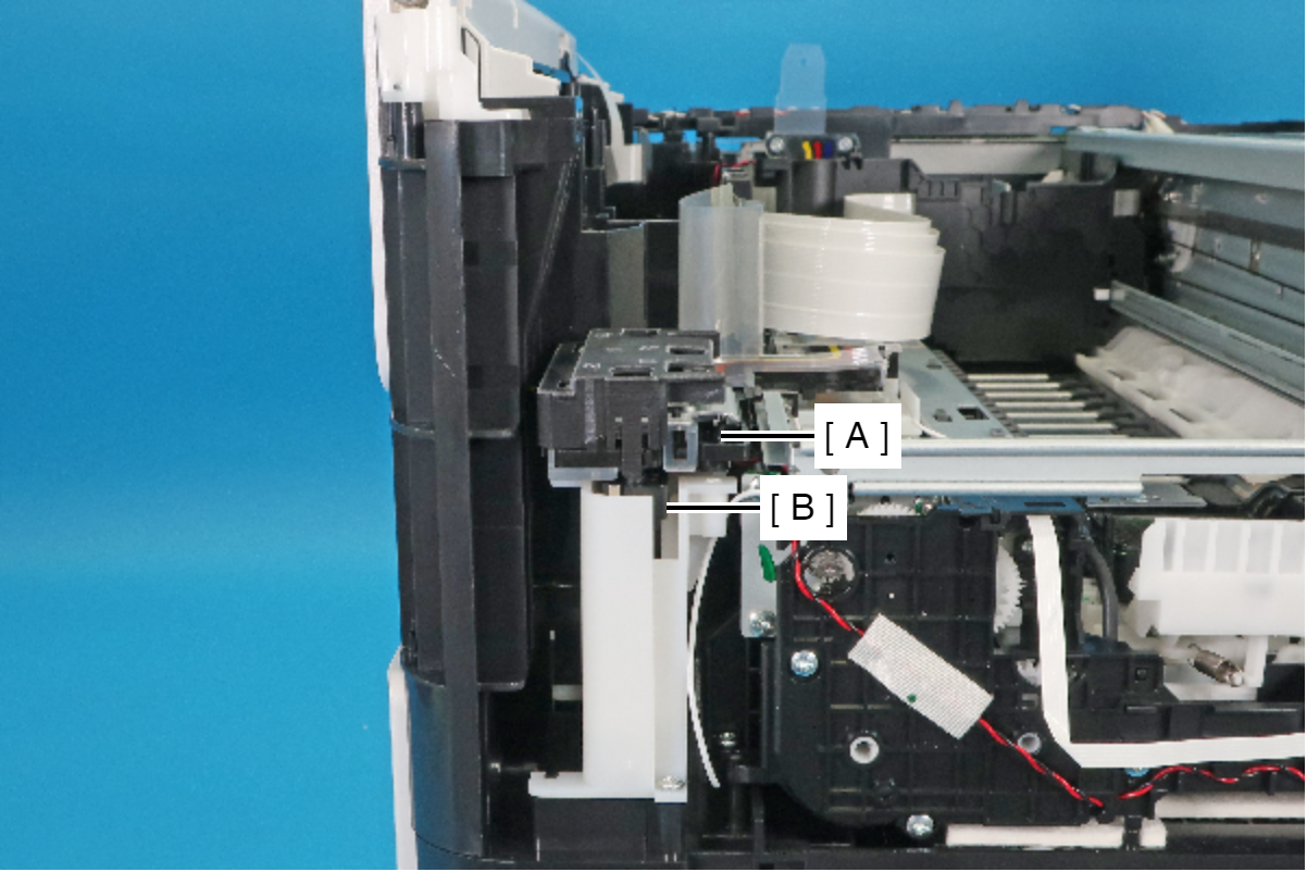
Assembly / 組み立てWhen disassembling/assembling, misalignment between tube of the Ink Supply Tube (A) and the joint part of the tube (B) affects ink supply.
Check that the Ink Supply Tube (A) and the joint section (B) are securely connected as in the figure below.
- Devise an ink leak strategy using waste cloths, etc., as displayed in the figure below, and avoid the ink supply tube (A).
- Slide the tube clamp (A), and remove the Wasted Ink Tube (C) from the Wasted Ink Duct Holder (B).
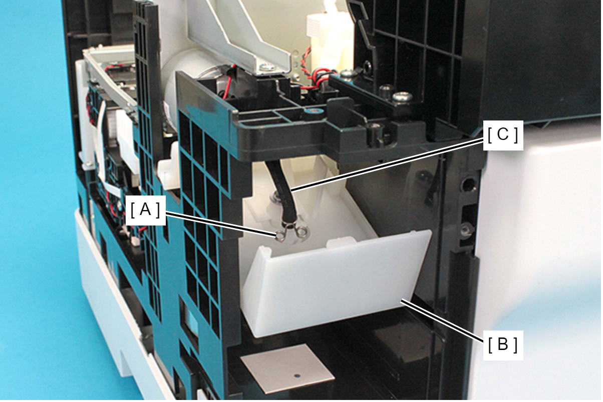 Caution / 注意
Waste ink may spill from the Wasted Ink Tube. Prepare waste cloths or similar in advance.
- Remove the three screws and remove the Upper Cap Frame (A).
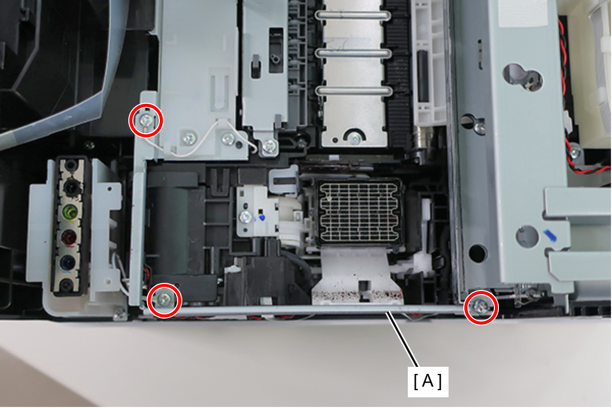
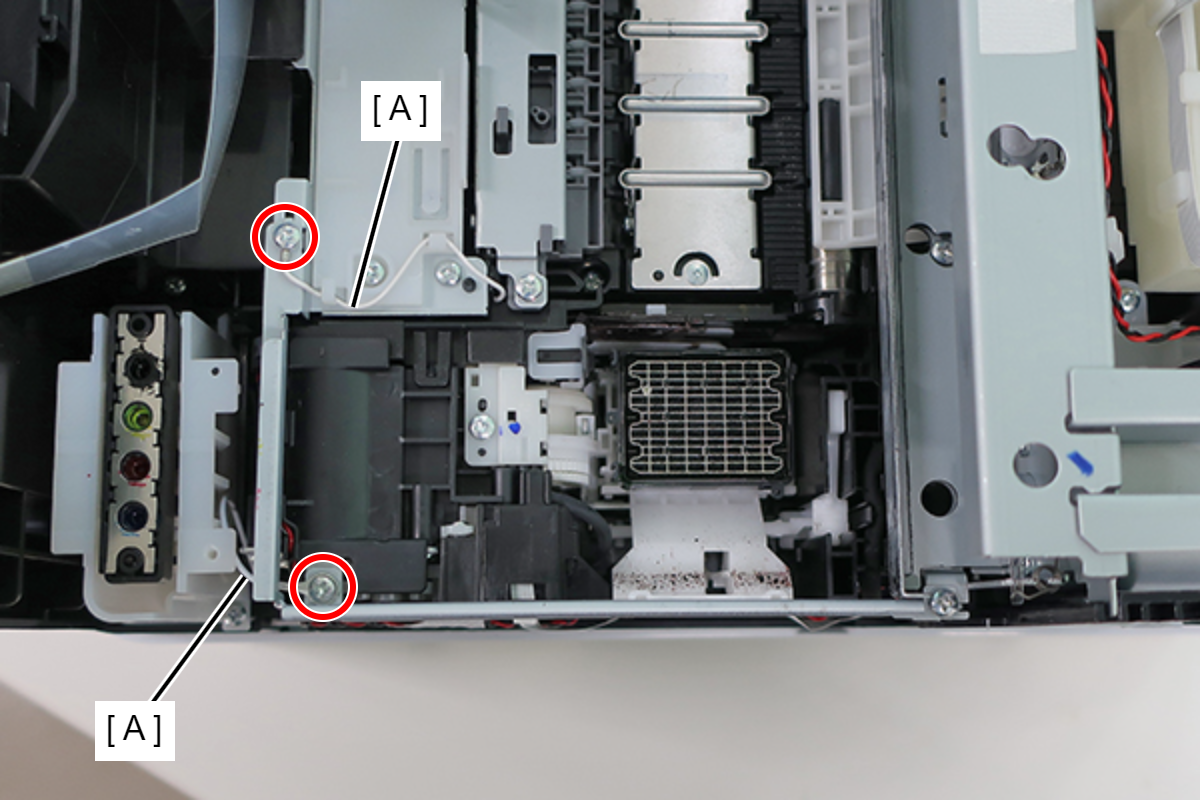
- : C.B.S-TITE-SCREW-3x6-F.ZN-3C
Assembly / 組み立てTighten the screw shown below together with the grounding wire (A).
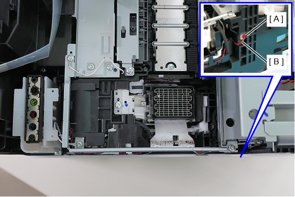
- Disconnect the cable (B) from the relay connector (A).
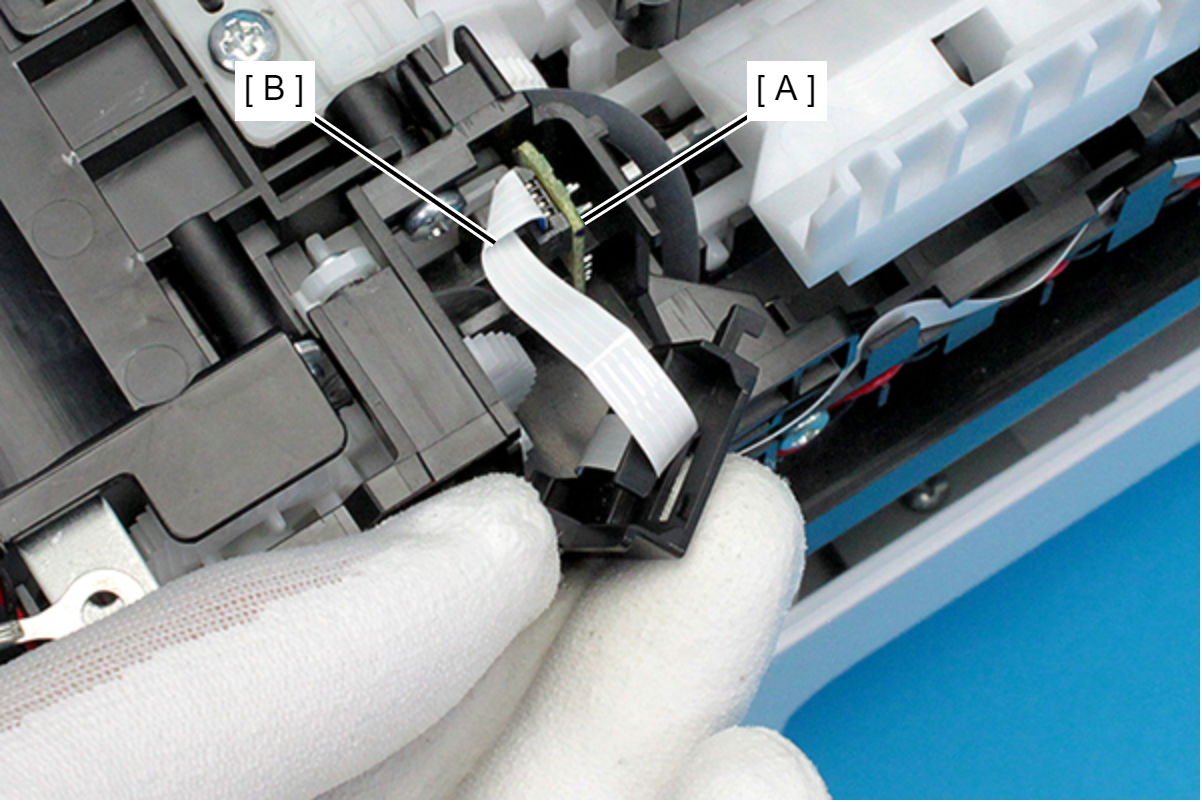
- Disconnect the FFC (B) from the Pump Encoder Sensor (A).
- Remove the four screws, and remove the Ink System Unit (A).
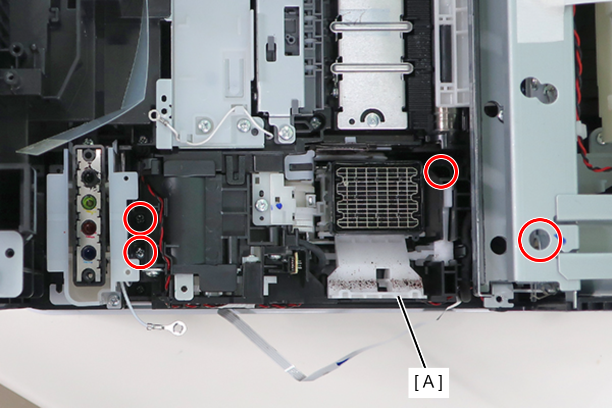
- : C.B.P-TITE-SCREW-3x10-F.ZN-3C
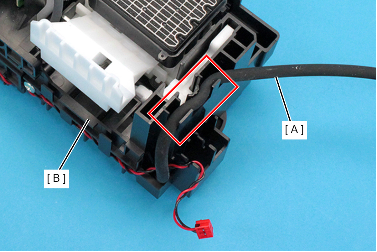
Assembly / 組み立て- Route the Wasted Ink Tube (A) through the guide on the Ink System Unit (B).
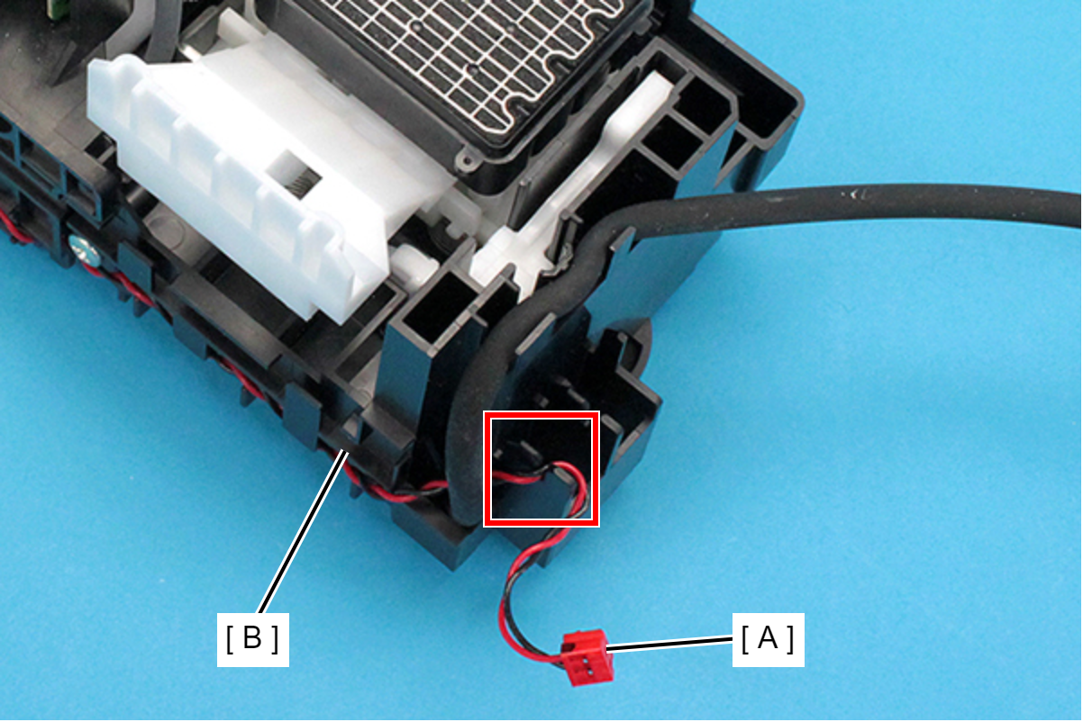
- Route the pump motor cable (A) through the slit on the Ink System Unit (B).
| Adjustment / 調整 |
After replacing this part, you need to run the menu from the service support mode. (If you ran the Before-replacement menu before replacing the part, it will start automatically when you turn the power on.) |